



Solidot XB6S – Support, Wiring Diagram & Commissioning
Everything for your Solidot XB6S after purchase – for all four bus couplers (PROFINET, EtherCAT, EtherNet/IP, Modbus TCP) with the digital, relay and analog modules:
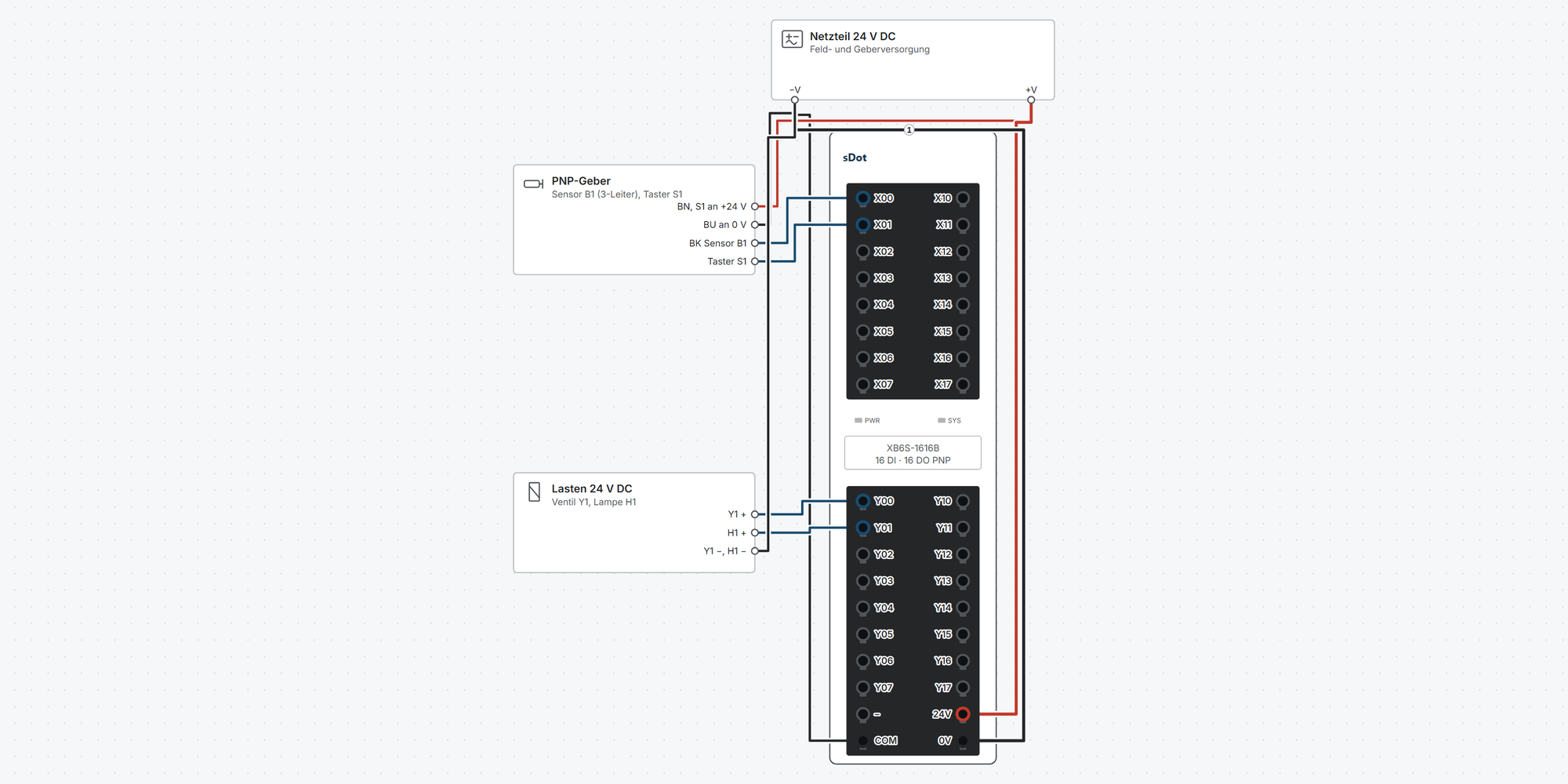
Interactive wiring diagram: power supply and power feed module with current budget on the backplane bus, PNP and NPN sensors, loads, relays, 0–10 V and 4–20 mA transmitters, analog outputs and the network to the controller, with cable cross-sections and parameters
Fieldbus: where every signal of your station ends up – for PROFINET, EtherCAT, EtherNet/IP and Modbus TCP
First steps: commissioning in 19 steps, from the DIN rail to the first signal in your controller
Dimensions & mounting: width of your station, DIN rail, minimum clearances and connectors
Downloads: 2D and 3D drawings, EPLAN macros and the IO Config Tool
Free support from spstiger if you get stuck
Interactive wiring diagram
Tap a terminal or wire in the drawing to see details.
Terminal overview XB6S
| Terminal | Group | mm² | Function |
|---|---|---|---|
| 24V | Supply | 0.3–1.5 | 24 V DC SELV (18–36 V), max. 600 mA. From this, the coupler generates 5 V / 2 A for the backplane bus (manual chap. 3.1.3). |
| 0V | Supply | 0.3–1.5 | Reference of the supply. Route system supply and field supply separately (manual chap. 5.2). |
| ⏚ | Supply | 0.3–1.5 | Earth reliably (manual chap. 5.2). |
| X1 | PROFINET | – | Two equivalent sockets with built-in switch. Cat5 or better, shielded (STP) recommended, max. 100 m (manual chap. 3.1.5). |
| X2 | PROFINET | – | Second socket of the switch: further device in line or PC for configuration. |
* Clamping range not stated in the manual, derived.
Fieldbus: the variables of your station
This shows where each signal of your station ends up in the controller – for the coupler you select above. You assemble the station in the wiring diagram (or here with “+ Add module”); the table updates right away.
PROFINET
- Device description file
- GSDML V2.43, on the PN2002 product page under “Downloads”
- Device name
- assign in TIA Portal, suggestion “pnio”
- IP address
- assigned by the controller
- Process data
- max. 1024 bytes of inputs and outputs combined
- Cycle
- from 1 ms (manual)
Where the variables are
With hardware detection, TIA Portal places each plugged-in module in slot 1, 2, 3 … and assigns the addresses. The table counts on from your start address, the way TIA assigns them when nothing before is occupied. The Device overview in TIA Portal is authoritative.
Factory default: voltage 0–10 V and current 4–20 mA, each as 0–27648.
EtherCAT
- Device description file
- ESI EcatTerminal-bus V3.0.13 (on the EC2002 product page under “Downloads”): _BOOL (individual channels) or _UINT (16 channels as a word), install only one
- Address
- via the position in the line, no IP address
- Process data
- max. 1024 bytes of inputs and outputs combined
- Cycle
- from 250 µs, without Distributed Clocks
Where the variables are
The master reads in the setup with a scan (TwinCAT “Scan for boxes”, CODESYS “Scan for Devices”). Each module is a slot: module n (the first one has n = 0) always sits in the same objects, inputs under 0x6000 + n · 0x10, outputs under 0x7000 + n · 0x10, parameters under 0x2000 + n · 0x10. The module order in the master must match the physical setup exactly (manual chap. 6.3).
Factory default: voltage ±10 V as −32768…32767, current 0–20 mA as 0–65535; switchable modules 4–20 mA as 0–27648.
You enter the startup parameters (measuring range, filter, substitute values) on the coupler: TwinCAT Box → Startup, CODESYS Startup Parameters tab.
EtherNet/IP
- Device description file
- EDS XB6S_EI2002 V0.03 (generic, on the EI2002 product page under “Downloads”), for KV STUDIO also the modular files
- Factory default IP
- 192.168.0.120 / 255.255.255.0
- Assemblies
- Inputs 100, outputs 150, configuration 151 (0 bytes)
- Process data
- max. 504 bytes each
- RPI
- 2–50 ms, factory default 30 ms
Where the variables are
The controller only knows two data blocks: inputs (instance 100) and outputs (instance 150). You enter their length as Input/Output Data Size – it is shown below for your station. The modules sit in them without gaps in slot order; with the status word enabled, 4 bytes come first (alarm code and station).
Factory default: voltage ±10 V as −32768…32767, current 0–20 mA as 0–65535; switchable modules 4–20 mA as 0–27648.
With the generic EDS, module parameters (measuring range, filter, substitute values) cannot be set from the controller, only with the Solidot IO Config Tool.
Modbus TCP
- Factory default IP
- 192.168.1.120 / 255.255.255.0, port 502
- Unit ID
- not stated in the manual
- Function codes
- 01, 02, 03, 04, 05, 06, 15, 16, 23
- Process data
- max. 512 bytes each
- Cycle
- at least 1 ms
Where the variables are
Each data type has its own area starting at 0; the modules fill it in slot order (derived from the example in the manual). A module with inputs and outputs therefore appears in two areas. The Configuration information page in the coupler's web interface is authoritative.
Factory default: voltage ±10 V as −32768…32767, current 0–20 mA as 0–65535; switchable modules 4–20 mA as 0–27648.
You set module parameters in the web interface (browser to the IP address), not via Modbus registers.
For specialists: Modbus areas according to the manual
| Data | Read | Write | Range (from 0) |
|---|---|---|---|
| Digital inputs as bits | FC 02 | – | 0–1023 |
| Digital outputs as bits | FC 01 | FC 05, 15 | 0–1023 |
| Analog inputs | FC 03 or 04 | – | 0–511 |
| Analog outputs | FC 03 from address 8192 (0x2000) | FC 06, 16 from address 0 | 0–511 |
| Digital inputs as 16-bit words | FC 03 from address 20480 (0x5000) | – | 0–127 |
| Digital outputs as 16-bit words | FC 03 from address 16384 (0x4000) | FC 16 from address 12288 (0x3000) | 0–127 |
| Diagnostics (2 registers per module: alarm code, channel) | FC 03 from address 24576 (0x6000) | – | 66 registers |
Manual chap. 6.5; the manual writes FC 15 and 16 as “0x15/0x16”, meaning decimal 15 and 16.
- Holding register 0 means analog input 0 when reading (FC 03) and analog output 0 when writing (FC 06/16). You read back analog outputs from 8192 (0x2000).
- Addresses from 10000 upwards (word areas 0x3000, 0x4000, 0x5000, diagnostics 0x6000) do not work in the 5-digit notation 40001.
The variables of your station
Process data per module (PROFINET and EtherNet/IP)
| Module | Inputs (bytes) | Outputs (bytes) | Channels |
|---|---|---|---|
| XB6S-1600 | 2 | 0 | 16 DI |
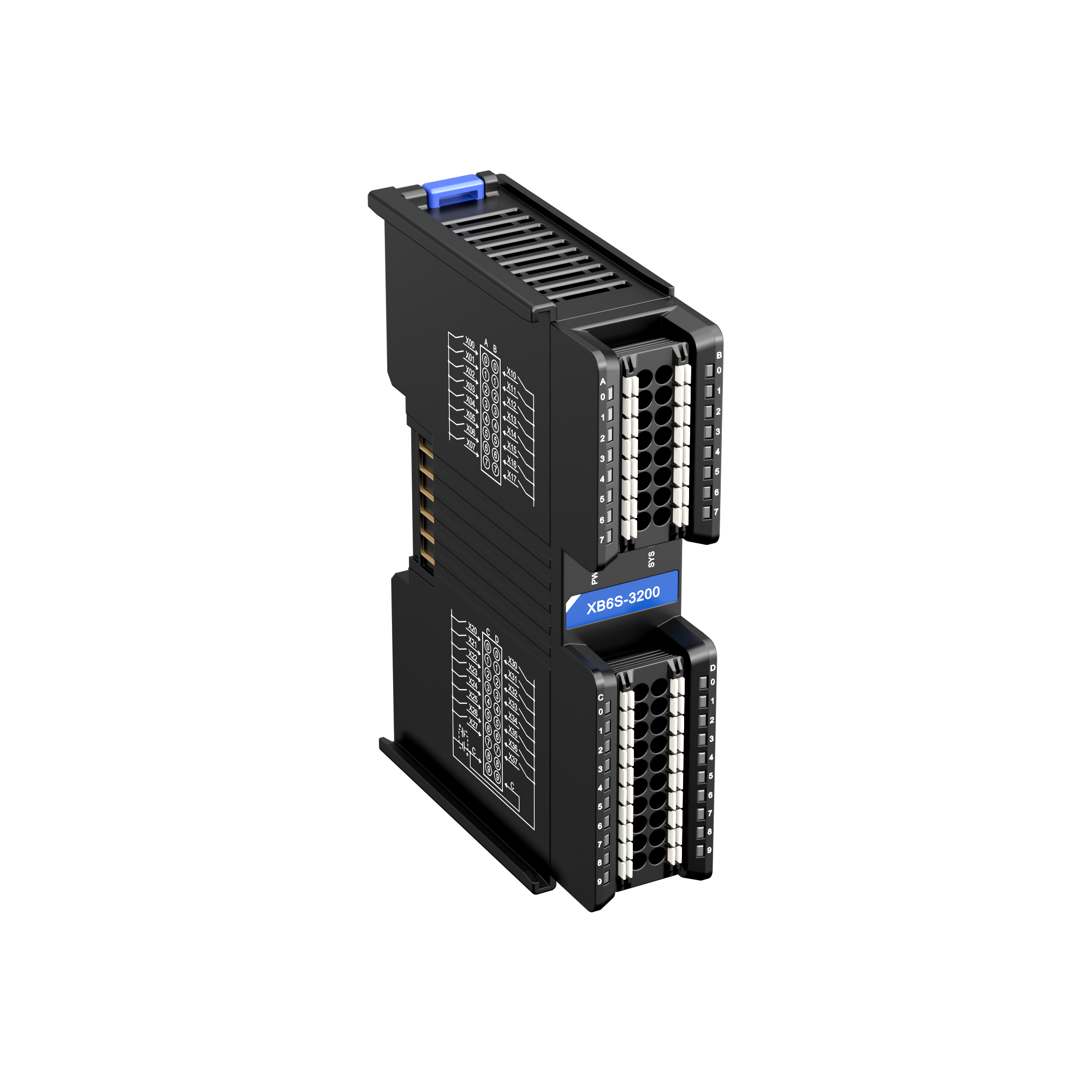
| XB6S-3200 | 4 | 0 | 32 DI |
| XB6S-0016B | 0 | 2 | 16 DO |
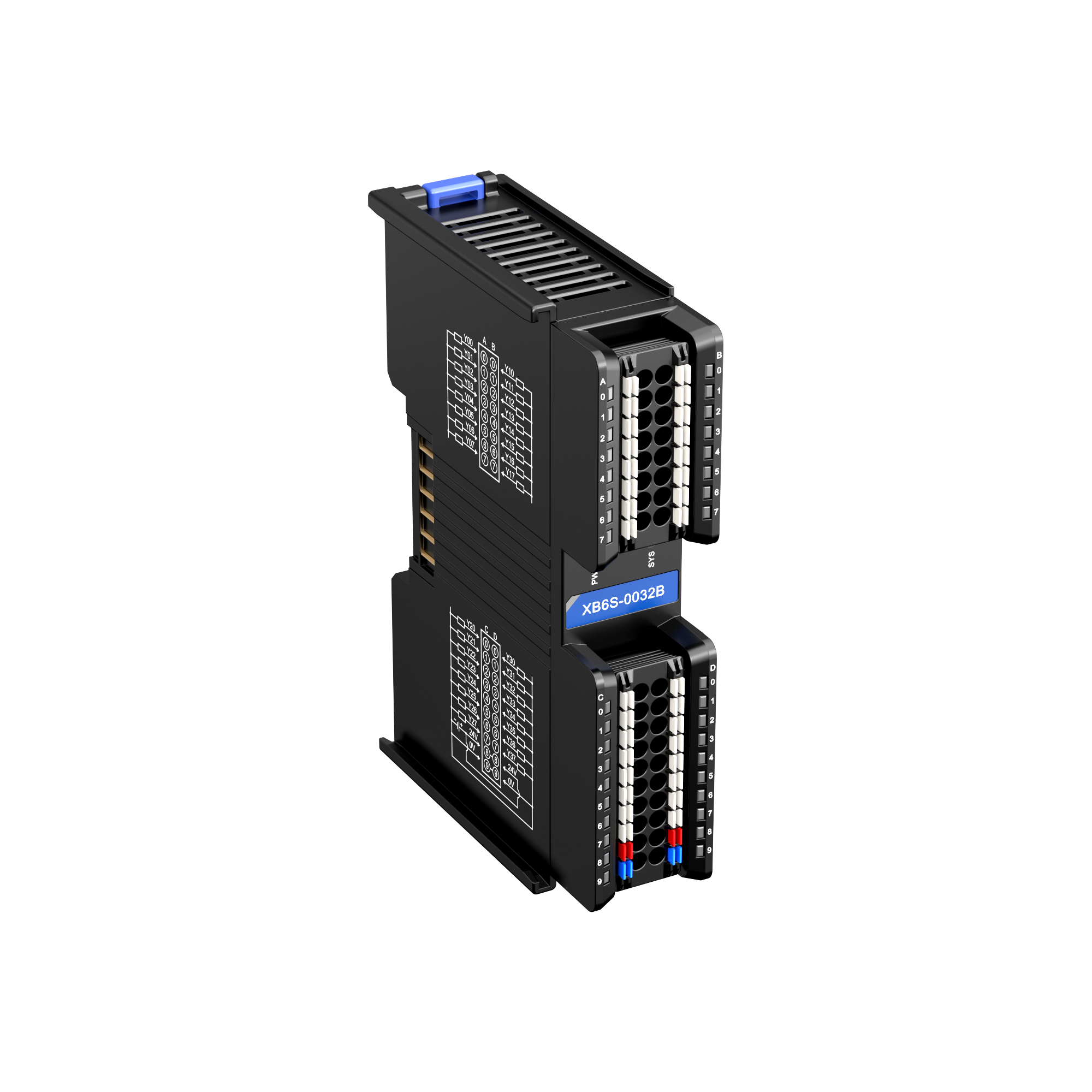
| XB6S-0032B | 0 | 4 | 32 DO |
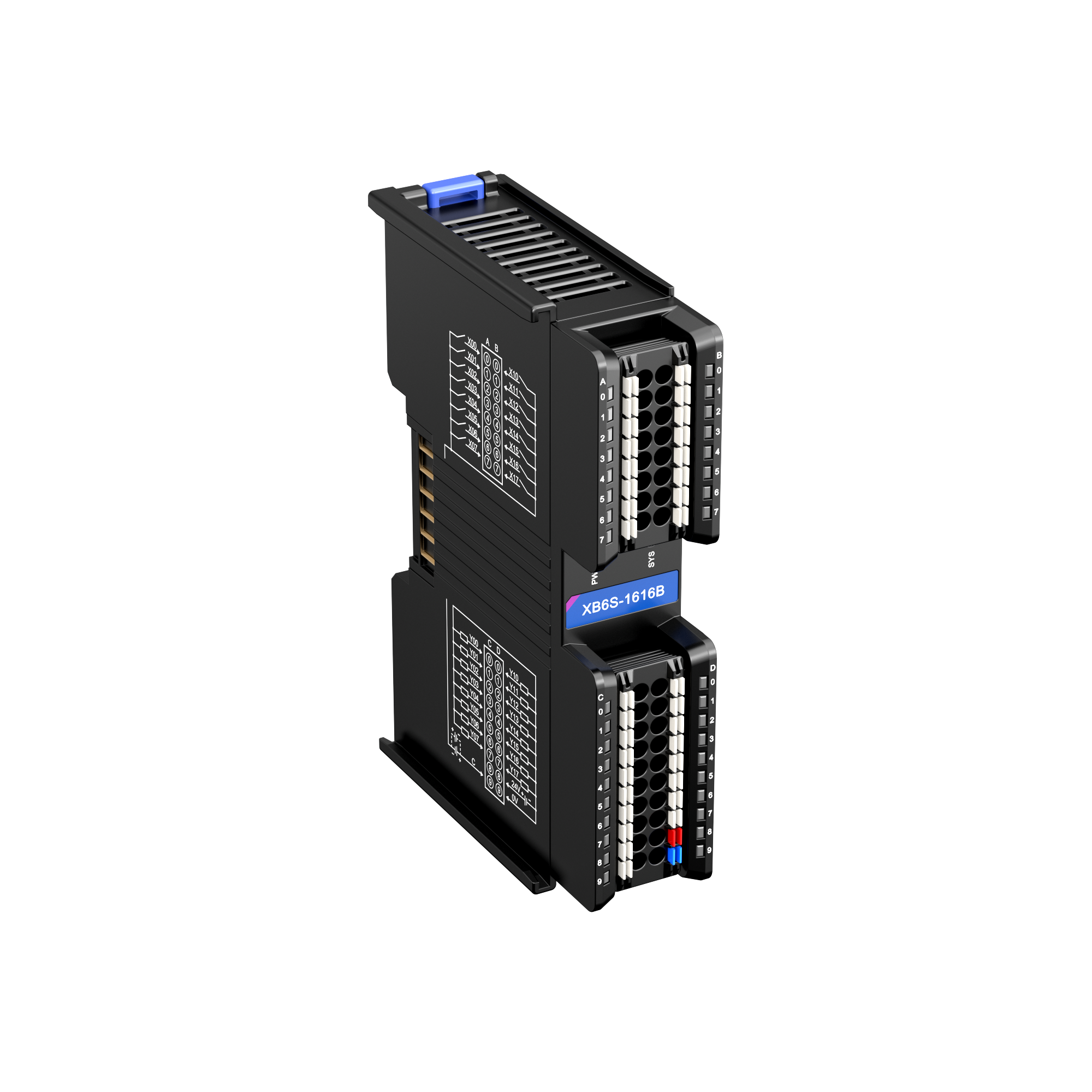
| XB6S-1616B | 2 | 2 | 16 DI, 16 DO |
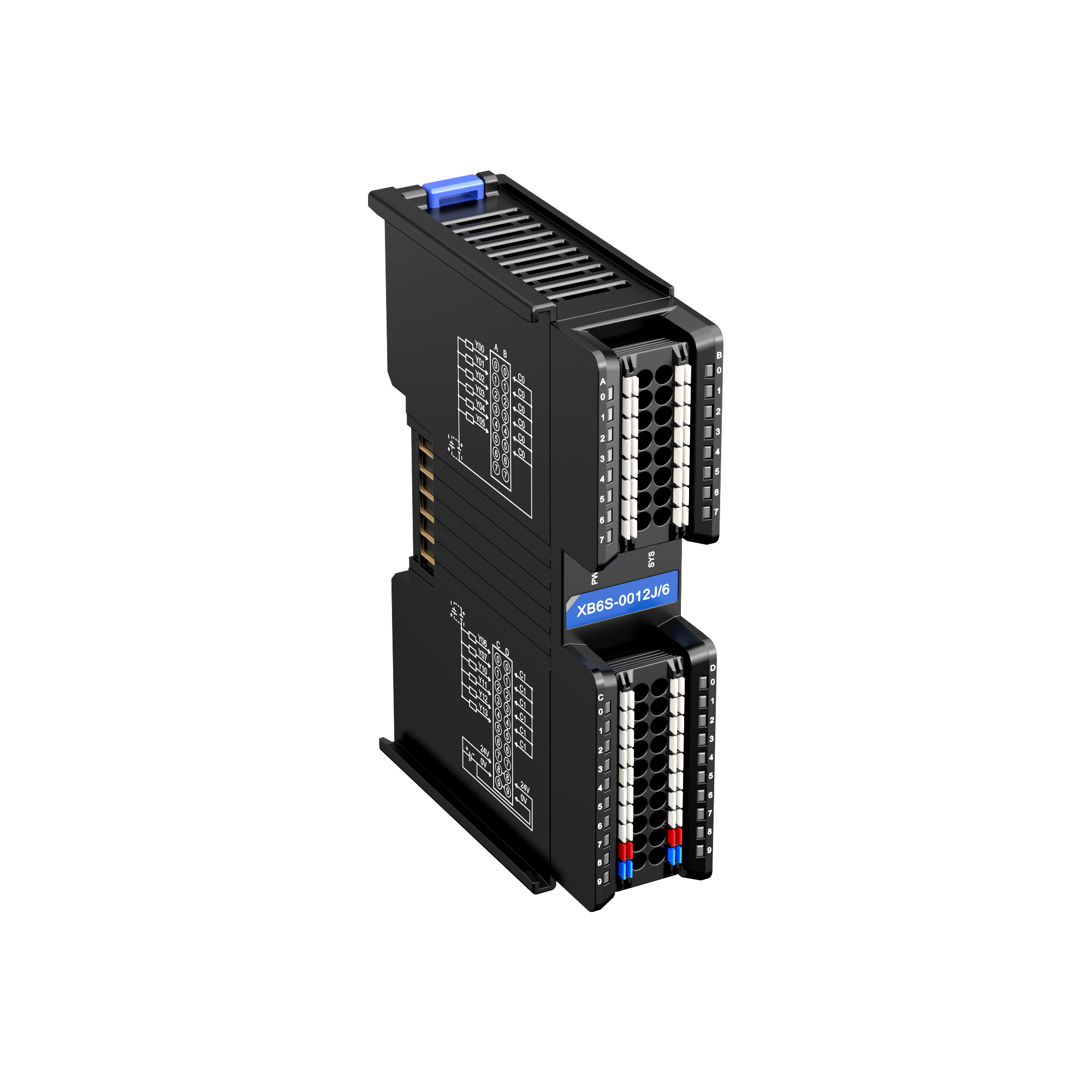
| XB6S-0012J/6 | 0 | 2 | 12 DO |
| XB6S-A40V | 8 | 0 | 4 AI |
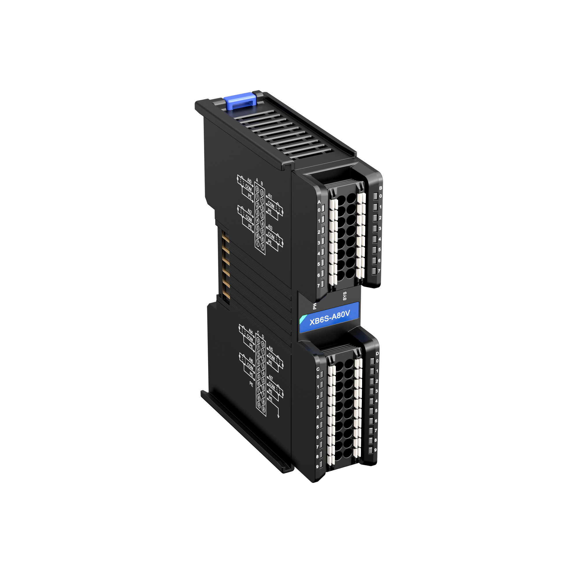
| XB6S-A80V | 16 | 0 | 8 AI |
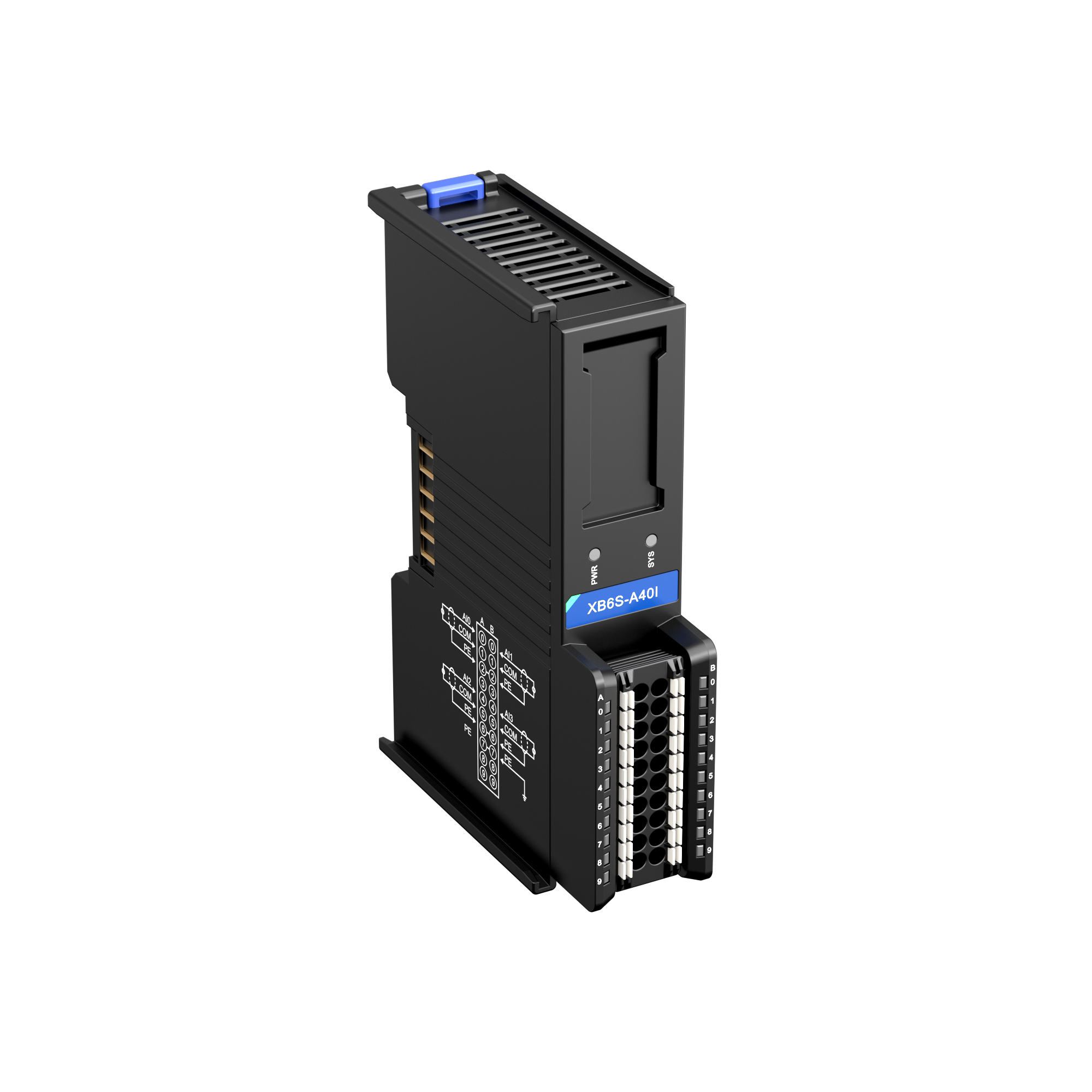
| XB6S-A40I | 8 | 0 | 4 AI |
| XB6S-A80I | 16 | 0 | 8 AI |
| XB6S-A40VD | 8 | 0 | 4 AI |
| XB6S-A80VD | 16 | 0 | 8 AI |
| XB6S-A40ID | 8 | 0 | 4 AI |
| XB6S-A80ID | 16 | 0 | 8 AI |
| XB6S-A40 | 10 | 0 | 4 AI |
| XB6S-A80 | 18 | 0 | 8 AI |
| XB6S-A04V | 0 | 8 | 4 AO |
| XB6S-A08V | 0 | 16 | 8 AO |
| XB6S-A04I | 0 | 8 | 4 AO |
| XB6S-A08I | 0 | 16 | 8 AO |
| XB6S-A04 | 0 | 8 | 4 AO |
| XB6S-A08 | 0 | 16 | 8 AO |
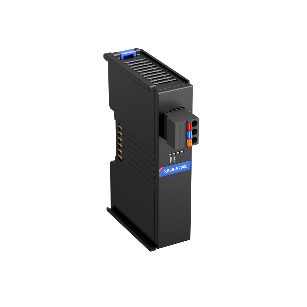
| XB6S-P2000 | – | – | power feed, no process data |
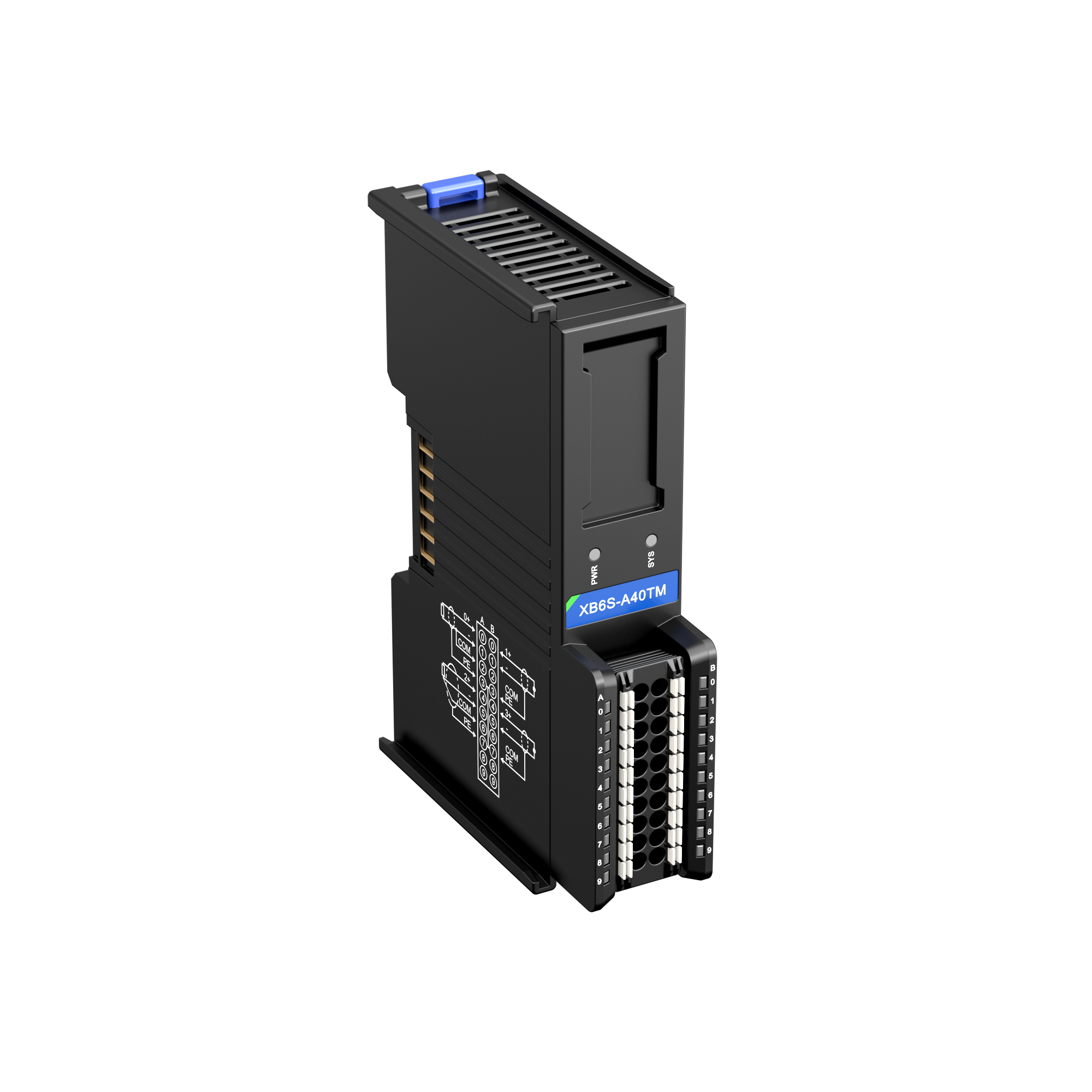
| XB6S-A40TM | 8 | 0 | 4 TM |
| XB6S-A80TM | 16 | 0 | 8 TM |
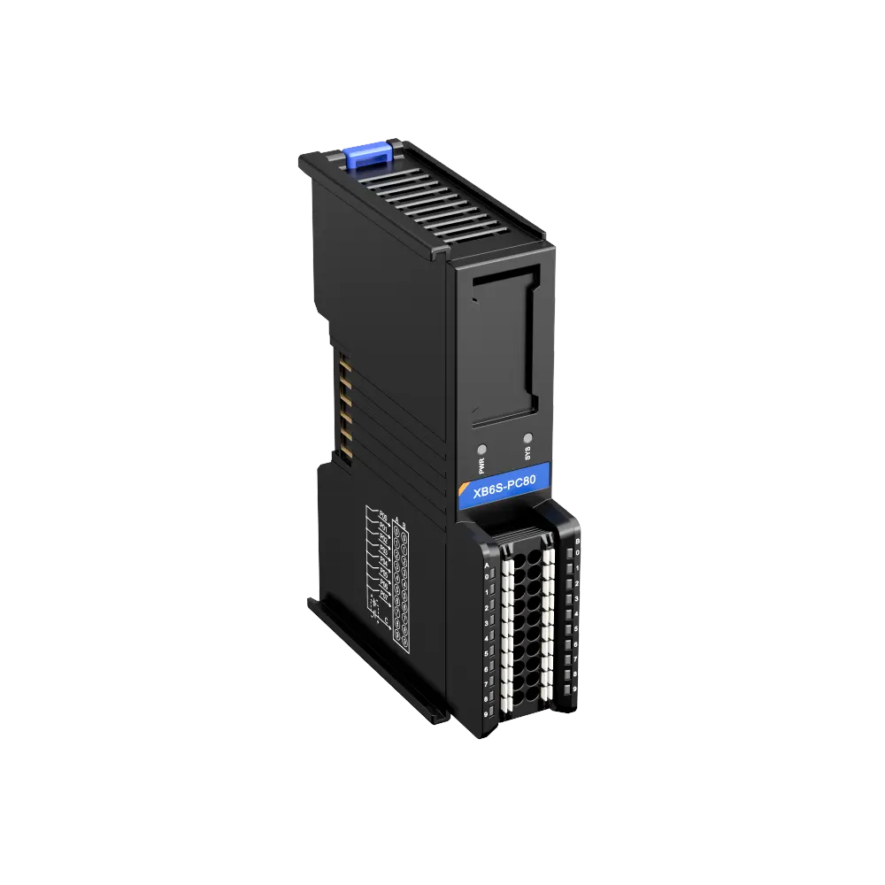
| XB6S-PC80 | 64 | 2 | 8 counters |
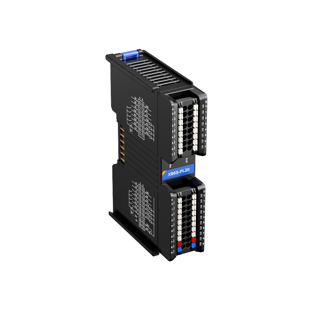
| XB6S-PL20 | 34 | 20 | 2 encoders HTL |
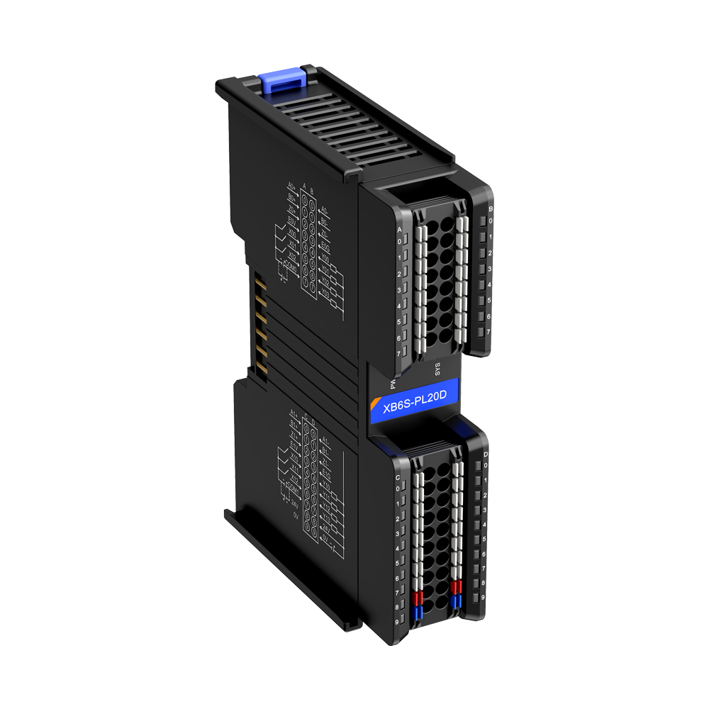
| XB6S-PL20D | 34 | 20 | 2 encoders TTL |
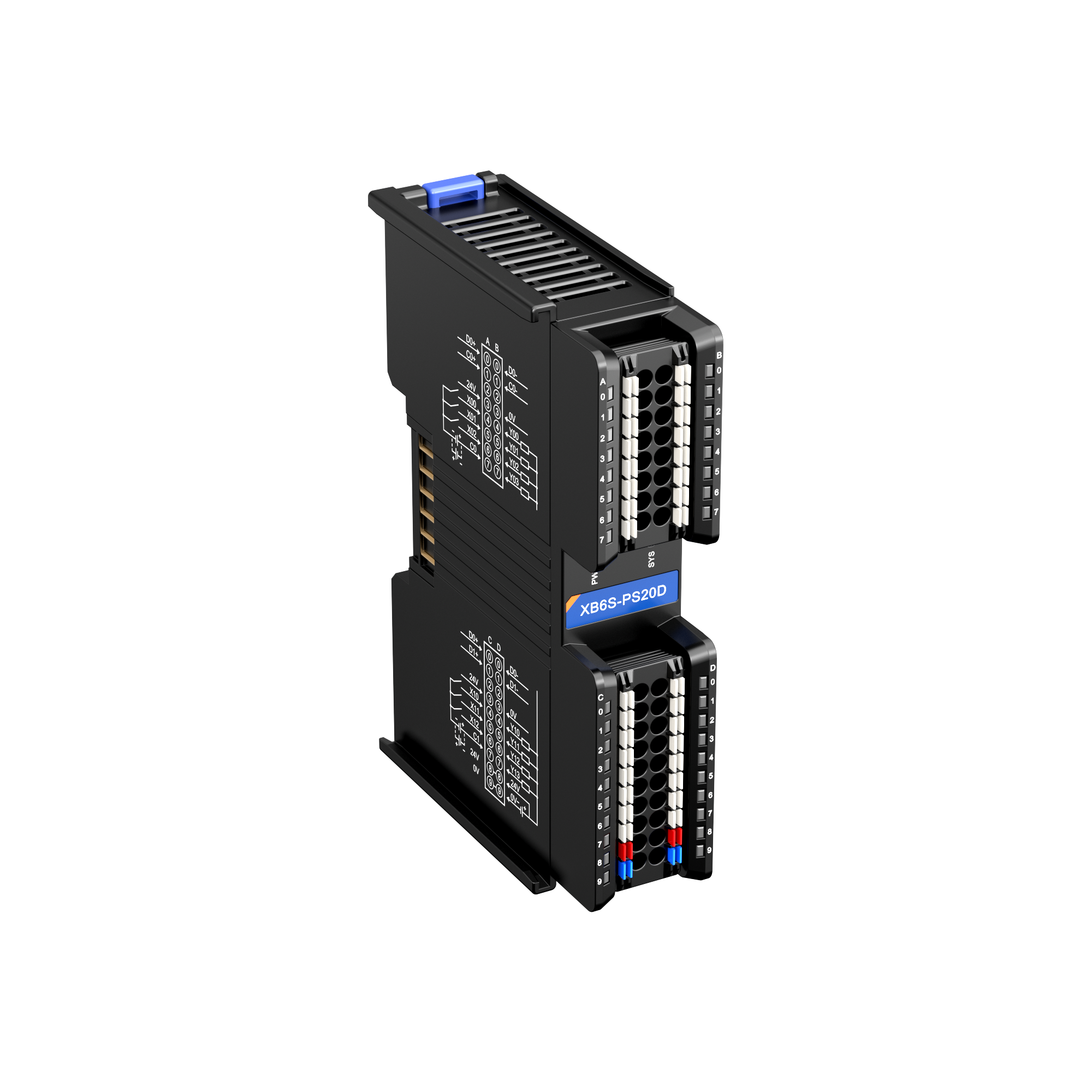
| XB6S-PS20D | 26 | 2 | 2 encoders SSI |
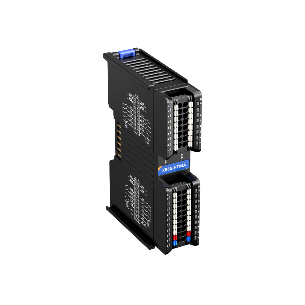
| XB6S-PT04A | 48 | 56 | 4 axes |
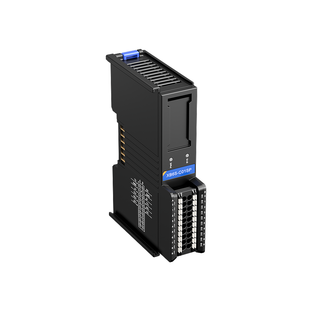
| XB6S-C01SP | 32 | 32 | Serial |
The switchable analog modules A40/A80 have 2 more bytes for wire-break detection.
- Process data per module from GSDML V2.43 and EI manual chap. 6.5.1 (they match). The channel assignment channel n = bit n mod 8 in byte n div 8 is derived.
- The P2000 power feed module occupies no process data and no slot in the GSDML and ESI.
- Counter, encoder, pulse output, temperature and serial: position of the variables from the GSDML, ESI and EtherNet/IP module description (status and control words first, then the values). The manual does not describe how these modules are mapped on the Modbus TCP coupler.
- C01SP: shown here with the factory default of 32 bytes; with 64, 128 or 255 bytes, the addresses of the modules after it shift.
Source: XB6S-PN2002 V1.22, -EC2002 V1.40, -EI2002 V1.20, -MT2002 V1.10 (chap. 6), GSDML V2.43 (22.06.2026), ESI EcatTerminal-bus V3.0.13, EDS XB6S_EI2002 V0.03.
First steps with the Solidot XB6S
The XB6S is a slice I/O system: a bus coupler for your network and up to 32 narrow I/O modules to its right. The hardware is the same for all four couplers; only the integration into the controller depends on the bus. Choose your coupler – then you only see the steps that apply to you.
Mount, wire and set the rotary switches only with the power off (manual chap. 4.1).
Degree of protection IP20: the station belongs in a control cabinet.
Route the system supply (coupler, P2000) and the field supply (terminals on the modules) separately and do not mix them; ground securely (manual chap. 5.2).
Copper wires only, rated for 80 °C.
Which bus coupler do you have?
1Plan the station: modules, order, bus currentRequired
The coupler sits on the left, with the I/O modules to its right in any order – up to 32 modules. The end cover goes on the far right (required).
Coupler and modules communicate via the backplane bus. For this, the coupler supplies 5 V with at most 2 A. If the modules need more, insert a power feed module XB6S-P2000 in between: it supplies the modules to its right with another 2 A.
Put your station together in the wiring diagram. The current budget per section appears below the module chain, and the Fieldbus tab then lists all variables.
Bus current of selected modules (5 V)
Module Bus current XB6S-1600 / 3200 80 / 100 mA XB6S-0016B / 0032B / 1616B 90 / 110 / 100 mA XB6S-0012J/6 100 mA XB6S-A80V 260 mA XB6S-A80VD / A80ID 210 mA XB6S-A80 100 mA XB6S-A08V / A08I / A08 100 mA The 2 A limit per section is derived from the device data; the manual does not state a rule. From 90 % load, the OVR LED on the coupler or P2000 lights up.
Source: Manual chap. 1.3, 3.1.3, 3.4
2Mount on the DIN railRequired
35 mm DIN rail, station mounted vertically with at least 50 mm clearance above and below the modules.
From left to right: coupler, modules (with a P2000 in between where needed), end cover. Snap each part on individually (click) and slide it sideways against the previous one until the fronts are flush.
Finally, fit an end stop to the left of the coupler and one to the right of the end cover and screw them tight.
Removal: loosen the end stops, release the latches at the top and bottom with a flat-blade screwdriver, pull the module off towards the front (manual chap. 4.3).
Source: Manual chap. 4
3Connect the supplyRequired
System supply: 24 V DC to 24V, 0V and earth on the coupler (3-pin, spring-clamp terminal), and likewise to each P2000.
Field supply: output modules, relay modules and analog outputs get 24 V at their own terminals (row 8/9 at the bottom). Input modules do not need one – there you connect COM to 0 V (PNP) or +24 V (NPN).
Route the system and field supply separately, even if both come from the same power supply unit.
Show wiring “24 V supply”Show wiring “Field supply for outputs”Show wiring “Field supply for analog outputs”Show wiring “Power feed P2000”
Source: Manual chap. 3.1.4, 3.2.4, 5.2
4Wire inputs and outputsRequired
All signal terminals are spring-clamp terminals (push-in) for 0.3–1.0 mm². Strip 10 mm of insulation; for fine-stranded wires, use a wire ferrule or press the release button. To release a wire, use a flat-blade screwdriver up to 3 mm wide.
Digital inputs: one logic per module – PNP with COM to 0 V, NPN with COM to +24 V. Digital outputs switch +24 V (PNP), up to 0.5 A per channel.
Use shielded twisted-pair cable for analog signals; shield to SHIELD. On the switchable A40/A80 you need a jumper AIx1–COM for current.
Show wiring “PNP sensors”Show wiring “Loads at Y00, Y01”Show wiring “Transmitter 4–20 mA, 2-wire”Show wiring “Current on channel 1”
Source: Manual chap. 3.2.4, 3.3.7, 5.2
5Switch on and check the LEDsRequired
After switching on, PWR lights up on the coupler. OVR must stay off, otherwise the backplane bus is overloaded.
As long as the controller is not yet exchanging data, IOR flashes at 1 Hz and SYS on the modules flashes at 1 Hz. That is correct – continue with your bus.
LED Meaning PWR on Supply OK OVR on Backplane bus ≥ 90 % loaded: insert a P2000 IOR 1 Hz waiting for the controller IOR on Process data exchange running IOE on Backplane bus fault (module, connector) Source: Manual chap. 3.1.2, 3.2.2
6PROFINET: install the GSDML and detect the stationPROFINETRequired
In TIA Portal
Unzip the GSDML ZIP from the XB6S-PN2002 product page (“Downloads” tab). Options → Manage general station description files (GSD), select the folder, install GSDML-V2.43-sDot-XB6S-PN2002.
In the device view, select the controller, Online → Hardware detection → PROFINET devices from network, select the interface, start the search.
Tick the coupler and click Add device: TIA adopts all plugged-in modules into slot 1, 2, 3 … in the correct order.
In the network view, click “Not assigned” on the coupler and select the PROFINET interface of the controller.
The P2000 power feed module does not appear in TIA: it has no process data.
Source: PN manual chap. 6.5.1
7PROFINET: assign the device name and downloadPROFINETRequired
Device name
Right-click the connection between controller and coupler → Assign device name.
Click Update list, identify the coupler by its MAC address (printed below the QR code) and click Assign name. The status must show “OK”.
Compile and download to the controller, then switch the coupler off and on once.
Go online: controller and coupler are green, IOR on the coupler lights steadily and BF is off.
You do not set an IP address on the coupler; the controller assigns it. The GSDML suggests “pnio” as the name.
Source: PN manual chap. 6.5.1
8PROFINET: parameters and first signalPROFINETRequired
Set the measuring range, filter and substitute values per module in the device view: select the module → Properties → Module parameters. Then download again and switch the station off and on.
For testing, create a watch table and enter the addresses. The address of each channel is in the Fieldbus tab – for your station and your start address.
Parameter Value Meaning Analog voltage 0–10 V = 0–27648 Factory default on the PN2002 Analog current 4–20 mA = 0–27648 Factory default on the PN2002 Digital outputs Preset Low set to 0 on bus failure The coupler can run as an MRP client in a ring; in that case, set the watchdog time above 200 ms (PN manual chap. 6.3).
Source: PN manual chap. 6.1, 6.5.1; GSDML V2.43
9EtherCAT: install the ESI fileEtherCATRequired
You will find the ESI file on the XB6S-EC2002 product page under “Downloads”. It comes in two versions: _BOOL shows each digital channel individually, _UINT combines 16 channels into one word. Install only one of them; both have the same device identity.
Software How to install the ESI TwinCAT 3 Copy the file to C:\TwinCAT\3.1\Config\Io\EtherCAT, restart TwinCAT CODESYS Tools → Device Repository → Install Sysmac Studio Right-click the EtherCAT master → Display ESI Library → Install (File) The cable from the master always goes into IN; OUT goes to the next device.
Source: EC manual chap. 6.3; ESI V3.0.13
10EtherCAT: scan the lineEtherCATRequired
The order and type of the modules in the master must exactly match the physical setup (EC manual chap. 6.3).
How to get the station into the master
TwinCAT: I/O → Devices → Scan, select the network adapter, confirm “Scan for boxes” and “Free Run”. The coupler appears as a box with all modules.
CODESYS: add an EtherCAT master, log in, then on the master Scan for devices → “Copy all devices to project”.
Sysmac Studio: insert the coupler from the Toolbox, enter the modules in slot order under “Edit Module Configuration” and write the node address.
Source: EC manual chap. 6.3
11EtherCAT: startup parameters and first signalEtherCATRequired
Enter the measuring range, filter and substitute values as startup parameters on the coupler: module n (the first one has n = 0) under 0x2000 + n · 0x10. TwinCAT: Box → Startup → New; CODESYS: Startup Parameters tab. Then reload and switch the station off and on.
The Fieldbus tab lists all objects (index:subindex) and parameter objects for your station.
Parameter Value Meaning Analog voltage ±10 V = −32768…32767 Factory default on the EC2002 Analog current 0–20 mA = 0–65535 Factory default on the EC2002 Analog outputs Clear set to 0 on bus failure RUN steadily on = OP. If ERR flashes at 2.5 Hz, the configuration does not match the physical setup (derived).
Source: EC manual chap. 6.1, 6.3; ESI V3.0.13
12EtherNet/IP: set the IP addressEtherNet/IPRequired
The factory default IP address of the coupler is 192.168.0.120. The easiest way to set the last octet is with the rotary switches ×100, ×10, ×1 (001–254, only with the power off), e.g. 0-2-1 for 192.168.0.21.
To use a different network, use the Solidot IO Config Tool: scan for devices, coupler → parameters → network parameters, send and restart the coupler.
Rotary switches IP address 000 (factory default) 192.168.0.120 or the address last set via software 001–254 192.168.0.xxx (upper octets from the software setting) 255–999 as at the last start Hold the reset button on top of the coupler for 3 s: IP address, parameters and the saved module chain return to factory default (EI manual chap. 6.2).
Source: EI manual chap. 3.1.2, 6.1, 6.2
13EtherNet/IP: configure modules with the IO Config ToolEtherNet/IPOptional
With the generic EDS, you set measuring ranges, filters and substitute values not from the controller but in the IO Config Tool: select the module, change the parameters, send.
There you also define whether the status word (4 bytes before the inputs) is sent along and what the outputs do in the IDLE state. With “Save configuration”, the coupler stores the module chain and later reports missing modules.
The IO Config Tool is available further down this page under Downloads.
Source: EI manual chap. 6.3, 6.6.1
14EtherNet/IP: integrate into the controllerEtherNet/IPRequired
General (example in the manual: Keyence KV STUDIO)
Register the EDS file XB6S_EI2002_V0.03 (on the XB6S-EI2002 product page under “Downloads”) in the controller software.
Insert the coupler with its IP address, connection Exclusive Owner.
Enter Input Data Size and Output Data Size – the values for your station are in the Fieldbus tab.
Select the RPI (2–50 ms, factory default 30 ms), transfer, set the controller to RUN.
The data follow one another without gaps in slot order; the Fieldbus tab shows which byte belongs to which channel.
For KV STUDIO, there are also the modular files: with them, you enter the modules individually and set the parameters from the controller.
Source: EI manual chap. 6.5, 6.6.2; EDS V0.03
15Modbus TCP: set the IP addressModbus TCPRequired
The factory default IP address of the coupler is 192.168.1.120, port 502. Set the last octet with the rotary switches ×100, ×10, ×1 (001–254, only with the power off).
To use a different network, go to the web interface: put the PC into the 192.168.1.x network, point the browser to the IP address, “Network parameters” at the bottom, save and restart.
Rotary switches IP address 000 (factory default) 192.168.1.120 or the address set in the web interface 001–254 192.168.1.xxx (upper octets from the web interface) 255–999 saved or factory default IP Hold the reset button on top of the coupler for 3 s until IOR and IOE light up briefly: IP address and parameters return to factory default (MT manual chap. 6.2).
Show wiring “PC for configuration”
Source: MT manual chap. 3.1.2, 6.1, 6.2
16Modbus TCP: check the station in the web interfaceModbus TCPRequired
The Overview shows the plugged-in modules with their LEDs. Clicking a module opens its parameters (filter, substitute values, measuring range) – send, done.
Configuration information shows the address table of each module. It is authoritative; the Fieldbus tab calculates the same addresses in advance from your planned station.
Parameters cannot be changed while a master is exchanging process data (MT manual chap. 6.6.1).
Source: MT manual chap. 6.3, 6.6.1
17Modbus TCP: set up the masterModbus TCPRequired
In the master (PLC, HMI or CODESYS), set up the coupler with its IP address and port 502, response timeout e.g. 1000 ms.
Then create one request per data type: digital inputs with FC 02, digital outputs with FC 15, analog inputs with FC 04, analog outputs with FC 16 – the start address and quantity for your station are in the Fieldbus tab under “All at once”.
When reading, holding register 0 is analog input 0; when writing, it is analog output 0. Read back the analog outputs from 8192.
Diagnostics: FC 03 from 24576 (0x6000), two registers per module (alarm code, channel).
The manual does not specify a unit ID.
Source: MT manual chap. 6.4.2, 6.5, 6.6.2
18Counters, encoders, temperature, pulse output, serial: what you need to setOptional
The special modules do little on their own by factory default: usually an enable bit or an operating mode is missing. You set parameters as for the other modules (PROFINET: module parameters, EtherCAT: startup parameters, EtherNet/IP: IO Config Tool, Modbus TCP: web interface). Then switch the module or the station off and on again.
The Fieldbus tab shows where count values, status words and control words are located in your controller.
PT04A: by factory default, Safe Mode is set to “keep running” – if communication fails, the axes keep moving. For machines with hazards, set it to “decelerate to stop”.
Module To get it running Factory default A40TM / A80TM Select the sensor type for the whole module (e.g. TC K); measured value in 0.1 °C PT100, internal cold junction PC80 Set the bit “CH[n] Enable”; clear with “CH[n] Clear Data” all channels disabled, filter 7 PL20 / PL20D Set bit 0 “Enable” in the encoder's control word; the parameters only take effect after that A/B ×1, power-failure retention on PS20D Adapt frame length, MSB/LSB, Gray/binary and clock rate to the encoder 13 bit, Gray, 2 MHz PT04A Write the ramps and speed, set the operating mode in the control word, then switch bit 4 “Start” from 0 to 1 pulse/direction, Safe Mode “keep running” C01SP Communication Mode (e.g. 1 = Modbus RTU master), interface and requests (node parameters) no function (Mode 0), 32 bytes After power-up, the PT04A shows error code 0x0601 until valid ramps and speeds have been written.
PL20/PL20D: Power-failure retention is on by factory default, so a configured start value has no effect.
Show wiring “HTL rotary encoder on encoder 0”Show wiring “Stepper drive on axis 0”Show wiring “RS-485 to Modbus device”Show wiring “Pt100 3-wire on channel 1”
Source: Module manuals PC80 V1.11, PL20 V1.11, PL20D V1.09, PS20D V1.17, PT04A V1.14, C01SP V1.10, T V1.19 (chap. 6–7)
19If something doesn't work: error codesOptional
The couplers report module errors with the same codes – PROFINET as an alarm in TIA, EtherCAT as an emergency in the master, EtherNet/IP in the status word, Modbus TCP from register 24576.
Code Meaning Remedy 0x00C5 No field voltage at the module Connect 24V/0V to the module 0x0184 Channel value out of range Check signal and measuring range 0x01C0 Parameter error Check module parameters 0x0FC1–0x0FC4 Backplane bus: startup, timeout, module disconnected, checksum Plug the modules in flush, check for sources of interference 0x2040 Wire break at the temperature module Check wiring By factory default, a module error makes the backplane bus stop data exchange for all modules until the error is cleared. With the coupler parameter “interactive”, the modules before the faulty one keep running.
Source: Manuals chap. 6.1, 6.2 or 6.4
Revision 1.1 · 04.10.2026 · Source: XB6S User Manual: PN2002 V1.22, EC2002 V1.40, EI2002 V1.20, MT2002 V1.10 (chap. 1–5 identical in all four, chap. 6 per bus); GSDML V2.43, ESI V3.0.13, EDS V0.03. TIA Portal menu names as in the English user interface shown in the manual. The manufacturer manual and applicable standards take precedence; installation and commissioning by a qualified electrician only.
Dimensions and mounting
The station sits vertically on a 35 mm DIN rail: coupler on the left, the modules to its right, the end cover on the far right. The drawing shows your station from the wiring diagram, projected from Solidot's 3D models.
Connectors and wires
Supply 24V · 0V · ⏚ (coupler, P2000)
- Type
- 3-pin, spring clamp (push-in)
- Cross-section
- 0.3–1.5 mm² (22–16 AWG)
- Strip length
- 10 mm
Signals (I/O modules)
- Type
- Spring clamp (push-in), 16-pin at the top and 20-pin at the bottom, or 20-pin at the bottom only
- Cross-section
- 0.3–1.0 mm² (22–17 AWG)
- Strip length
- 10 mm
Network X1/X2 or IN/OUT
- Type
- 2 × RJ45, Cat5 or better, shielded (STP) recommended, max. 100 m
Wire ferrules with plastic collar, sleeve length 10 mm: E0310 (0.3 mm²), E0510 (0.5), E7510 (0.75), E1010 (1.0), E1510 (1.5 mm², supply only).
Copper wires rated for 80 °C only. Cross-sections, ferrules and strip length: manual chap. 5.1 and 5.2.
Mounting step by step
1Choose the installation site
Degree of protection IP20: the station belongs in a control cabinet.
Mount the station vertically on a horizontal DIN rail (35 × 7.5 mm or 35 × 15 mm) and leave 50 mm of clearance above and below the modules. The wires run off upwards and downwards.
Operating temperature −20 to 60 °C; above 45 °C the transistor outputs may deliver less current, above 50 °C the relays.
2Mounting the station
Mount only with the power off.
Place the coupler on the DIN rail and snap it in (click).
Snap in each module individually and slide it to the left against the previous one until the backplane contacts engage and the fronts are flush. A P2000 goes in front of the first module it is to supply.
Fit the end cover on the far right – it is mandatory.
Place an end stop to the left of the coupler and to the right of the end cover and screw them tight.
3Replacing a module
Switch off the power, loosen the end stops.
Slide the modules to the right of the module in question a little to the right.
Open the latches at the top and bottom with a flat-blade screwdriver and pull the module off towards the front.
Snap in the new module, slide the station back together, screw the end stops tight.
4Connecting the wires
Strip 10 mm of the wire. Stranded wires get a wire ferrule with a 10 mm sleeve length; solid wires go in directly.
To release, press the push button with a flat-blade screwdriver (up to 3 mm).
Signal terminals take 0.3–1.0 mm², the supply terminal on the coupler and P2000 0.3–1.5 mm².
Revision 1.0 · 04.10.2026 · Source: XB6S User Manual (PN2002 V1.22) chap. 3.1.3, 3.2.3.5, 3.3.3.5, 3.4, 3.6 and 4; Solidot 3D models XB6S V1.02. The manufacturer manual and applicable standards take precedence; installation by a qualified electrician only.
Stuck?
Our support helps you free of charge. Tell us what you are planning and which model you use – via the contact form, by email or in the community forum.
Contact formEmail support@spstiger.deAsk in the community forum
More ways to contact us: Support contacts
We have compiled and checked this page carefully from the manufacturer’s documentation. Even so, an error may have slipped in. The manufacturer’s manual and the applicable standards always take precedence. Spotted something? Let us know – we’ll be glad to fix it.
Downloads
You will find the manual and device description file (GSDML, ESI or EDS) of your bus coupler on the coupler’s product page under “Downloads”:
The manuals of the special modules (temperature, counter, encoder, pulse output, serial) are also on their product pages.
Here for the whole series: 2D and 3D drawings, EPLAN macros and the IO Config Tool:
Solidot XB6S slice I/O
Accessories