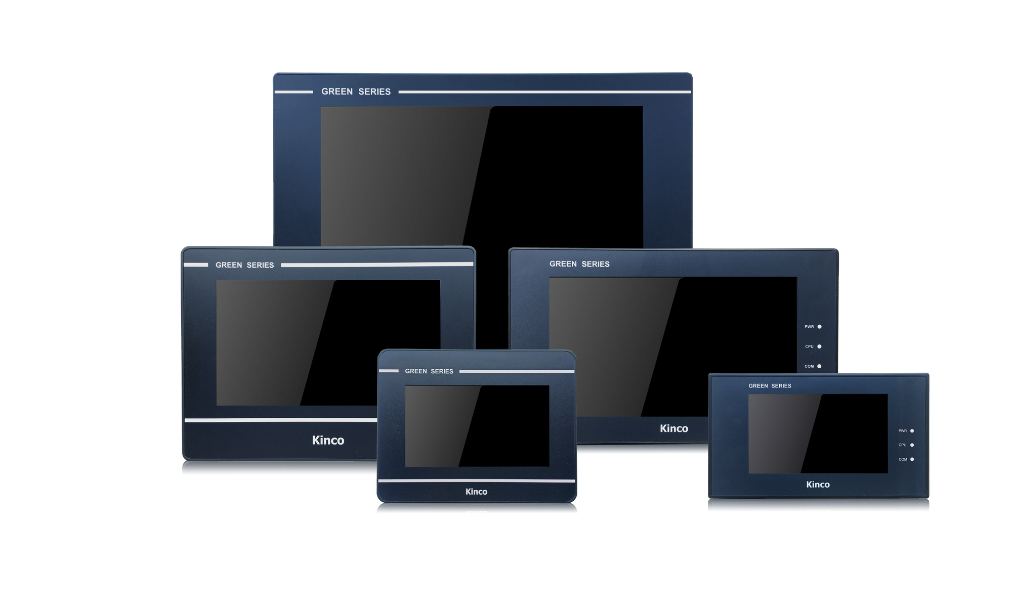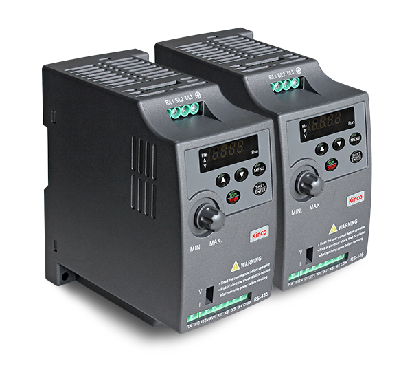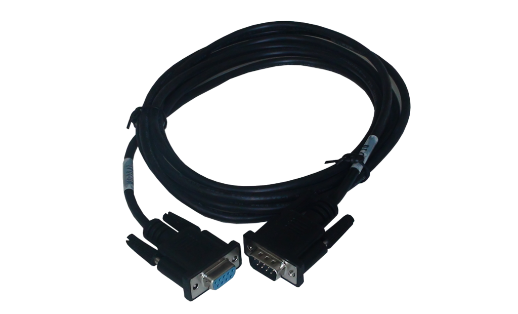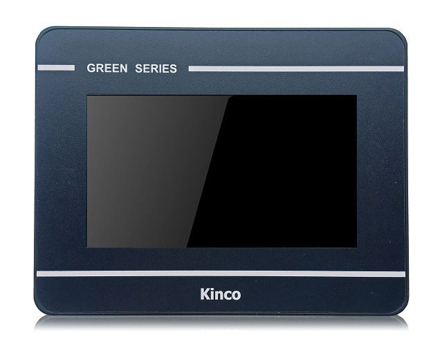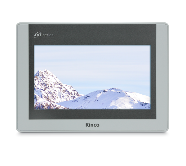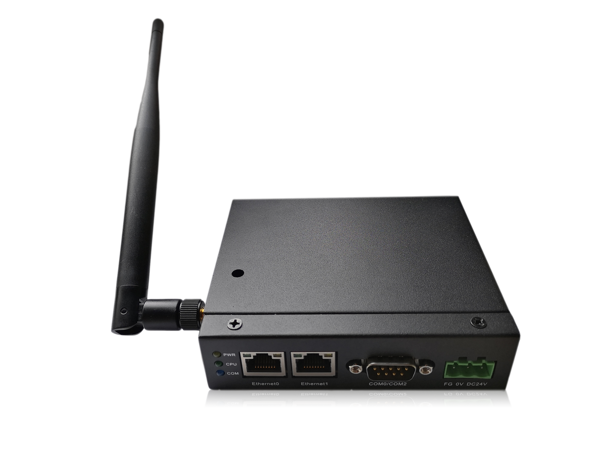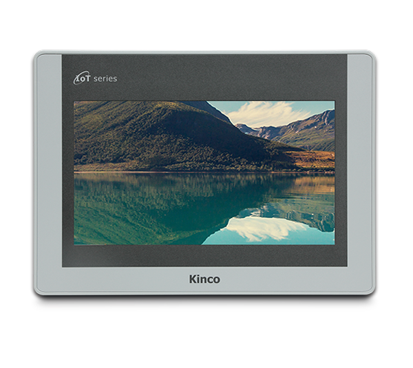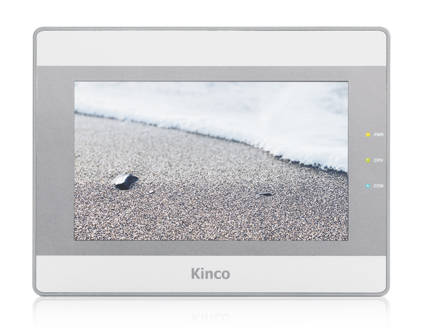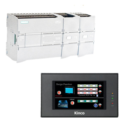
Kinco HMIs are an inexpensive visualization and operating option for Siemens S7 PLCs. Siemens S7 PLCs can be easily combined with Kinco HMIs. Select your PLC model and the desired connection type to see how the HMI and PLC are connected.
The programming software (German) for the Kinco HMI is completely free of charge. You can download and test it on the respective device.
Below you will find an overview of all Kinco HMIs. Simply select the right size for your visualization project.
Select your PLC model and a connection type to find out more about the communication settings:
-
Simatic S7-1200
-
Ethernet
- Connection
- Driver configuration in Kinco HMIware
- Configuration of the S7-1200
- Addressing
Connecting the Simatic S7-1200 via Ethernet
The Simatic S7-1200 can be easily connected to the Kinco HMI via Ethernet. Either via a direct LAN connection or via a hub or switch. This means that several S7-1200s can also be visualized on the Kinco HMI via the LAN.
All Kinco HMIs in our online store have a standard RJ-45 Ethernet connection for this purpose.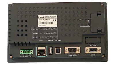 The Ethernet connection of a 7" Kinco MT4424TE HMI
Driver configuration for S7-1200 via Ethernet in the Kinco HMIware
The appropriate driver in the Kinco HMIware for connecting the S7-1200 PLC via Ethernet is the Siemens S7-1200 Ethernet (TCP slave) driver.
All Kinco HMIs with an Ethernet connection can communicate with the Siemens S7-1200 via Ethernet. To do this, a project must be created accordingly in the Kinco HMIware, the communication configured and the project transferred to the HMI. The configuration is carried out in the following steps
.- Create a new project in the Kinco HMIware or open an existing project
- Drag the HMI used in the HMI tab into the project
- Under PLC, drag the Siemens S7-1200 Ethernet (TCP Slave) into the project
- Open the configuration of the LAN by double-clicking on the PLC, then "Network Device Settings"
- Add the PLC under "Add" and configure the IP of the PLC
- Add the HMI under "Add" and configure the IP of the HMI
- Close all open windows with Ok
- Create screens and objects that are linked to variables in the PLC (more on this under Addressing)
- Compile the project and transfer it to the HMI via download
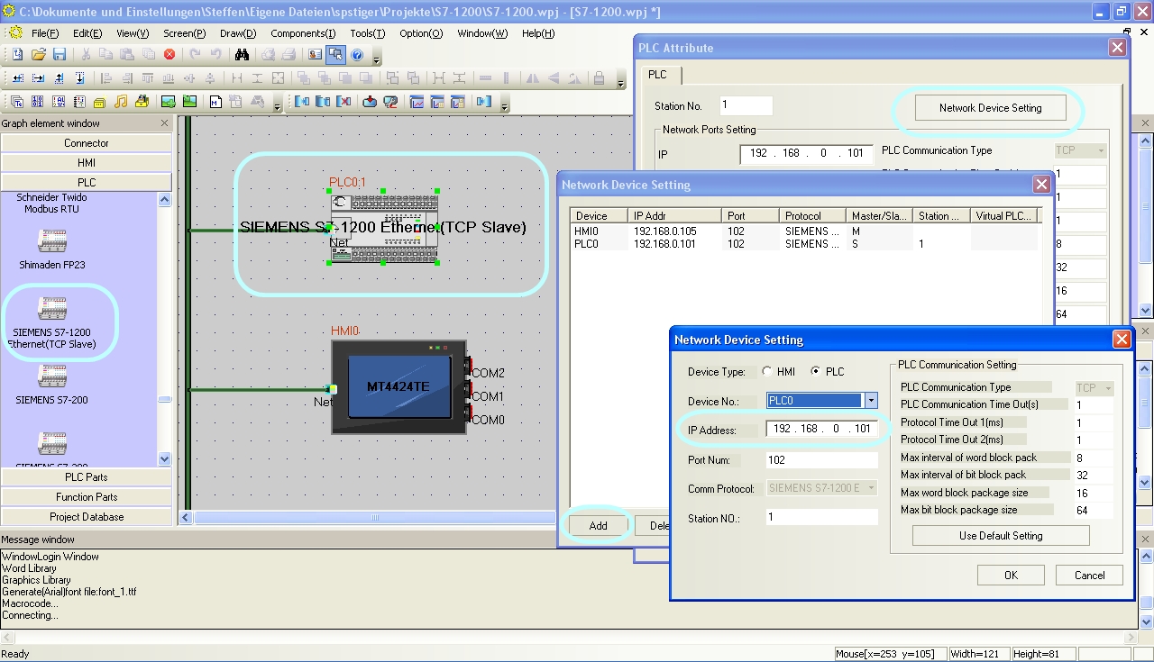 Configure the communication between Kinco HMI and Siemens S7-1200 via Ethernet in the Kinco HMIware.
The full version of the programming software for the Kinco HMI can be downloaded here
Kinco HMIware 2.0 (248 MB)
Configuration in the Simatic S7-1200
Configure the IP address and data blocks in the S7-1200 via your S7 software. Configure the IP via the Profinet interface. Add the data blocks accordingly.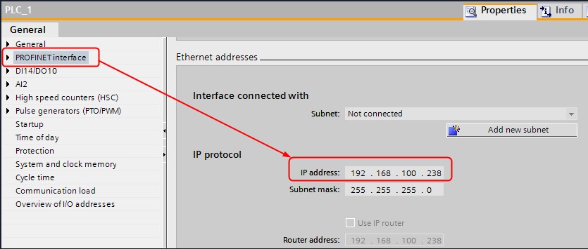 The configuration of the IP address of the S7-1200.
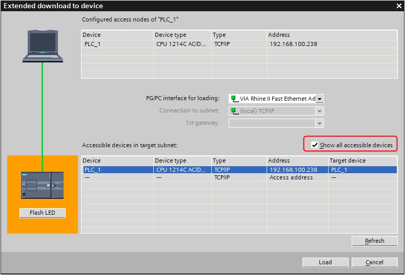 Download the configuration of the IP address of the S7-1200.
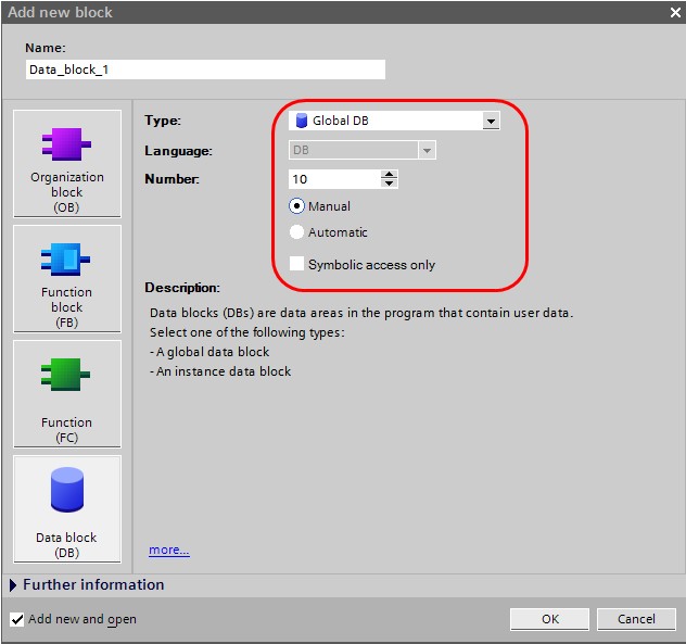 Configuration of a data block in the S7-1200.
Addressing the Siemens PLC variables
Kinco HMI elements
Kinco HMIware provides a large selection of elements for visualizing and changing PLC data. These include, for example, switches, lamps, input fields and much more. These elements can be easily linked to variables in the PLC. The variables listed below are available for the Siemens S7-1200.
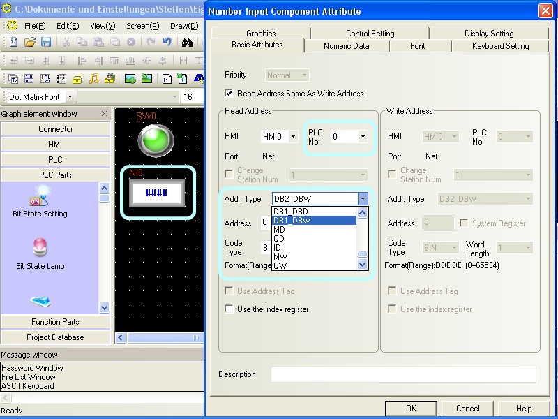 Selecting a variable in an HMI element in the Kinco HMIware
Bit addresses
You can use the following address ranges in the S7-1200 to link to bit elements such as switches or lamps:
- Flags (M.B 0.0-2047.7)
- Outputs (Q.B 0.0-127.7)
- Inputs (I.B 0.0-127.7)
- Bits in data blocks (e.g. DB1_DBX 0.0-65535.7)
Make sure to use dot notation for addressing.
Word and Double Word addresses
You can use the following address ranges in the S7-1200 to link to Word or Double Word elements (16-bit or 32-bit) such as input fields, position animations, fill levels, etc.:
- Flag blocks, addressed 16-bit-wise (MW 0-2046)
- Flag blocks, addressed 32 bits at a time (MD 0-2044)
- Output blocks, addressed 16 bits at a time (QW 0-126)
- Output blocks, addressed 32 bits at a time (QD 0-124)
- Input blocks, addressed 16 bits at a time (IW 0-126)
- Input blocks, addressed 32 bits at a time (ID 0-124)
- Data blocks, 16-bit addressed (e.g. DB1_DBW 0-65534)
- Data blocks, addressed 32 bits at a time (e.g. DB1_DBD 0-65532)
larger than 10
Separate address ranges are available for addressing data blocks up to 10. There is a DBn_Dxx area for data blocks larger than 10. Any data blocks can be addressed via this area. The first one to three digits stand for the data block (1..255) and the following five digits for the address of the variable (00001..65536).
Examples:- DBn_DBW with address 100001 is word 1 in data block 1
- DBn_DBW with address 1200012 is Word 12 in data block 12
- DBn_DBW with address 11200318 is Word 318 in data block 112
These DBn address ranges are available for bit (DBn_DBX), word (DBn_DBW) and double word (DBn_DBD) addressing.
Further information on programming the Kinco HMI can be found in our online course
Kinco HMIware online course
-
-
Simatic S7-200
-
Ethernet
- Connection
- Driver configuration in Kinco HMIware
- Configuration of the S7-200
- Addressing
Connecting the Simatic S7-200 via Ethernet
The Simatic S7-200 can be easily connected to the Kinco HMI via Ethernet. Either via a direct LAN connection or via a hub or switch. This also allows several S7-200s to be visualized on the Kinco HMI via the LAN.
All Kinco HMIs in our online store have a normal RJ-45 Ethernet connection for this purpose.
 The Ethernet connection of a 7" Kinco MT4424TE HMI
Driver configuration for S7-200 via Ethernet in the Kinco HMIware
The appropriate driver in the Kinco HMIware for connecting the S7-200 PLC via Ethernet is the Siemens S7-200 Ethernet (TCP slave) driver.
All Kinco HMIs with an Ethernet connection can communicate with the Siemens S7-200 via Ethernet. To do this, a project must be created accordingly in the Kinco HMIware, the communication configured and the project transferred to the HMI. The configuration is carried out in the following steps
.- Create a new project in the Kinco HMIware or open an existing project
- Drag the HMI used in the HMI tab into the project
- Under PLC, drag the Siemens S7-200 Ethernet (TCP Slave) into the project
- Double-click on the PLC, then "Network Device Settings" to open the LAN configuration
- Add the PLC under "Add" and configure the IP of the PLC
- Add the HMI under "Add" and configure the IP of the HMI
- Close all open windows with Ok
- Create screens and objects that are linked to variables in the PLC (more on this under Addressing)
- Compile the project and transfer it to the HMI via download
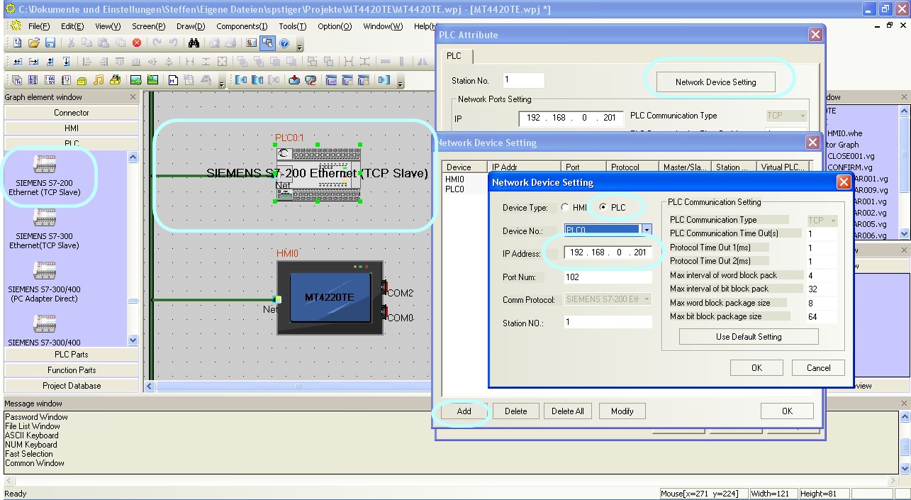 Configure the communication between Kinco HMI and Siemens S7-200 via Ethernet in the Kinco HMIware.
The full version of the programming software for the Kinco HMI can be downloaded here
Kinco HMIware 2.0 (248 MB)
Configuration in the Simatic S7-200
Configure the IP address and data blocks in the S7-200 via your Step 7 Micro/WIN software. You carry out the Ethernet configuration via the Ethernet Wizard in the Tools menu. Here are the most important steps.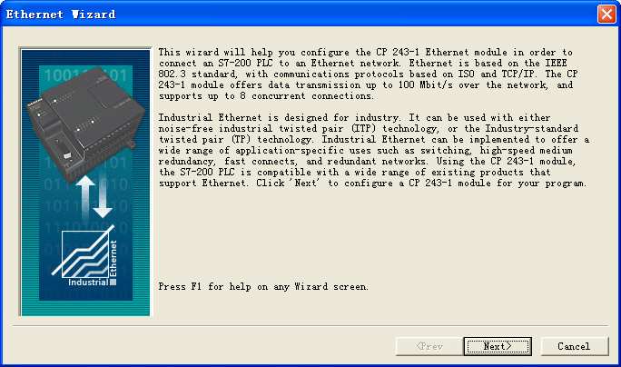 First window of the Ethernet Wizard, which is called up via the Tools menu.
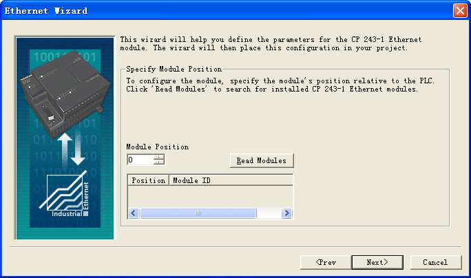 For the connection to the Kinco HMI to work, the Ethernet module must be in position 0. If necessary, change the position of the module
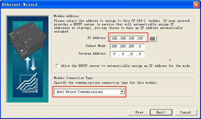 Configure the IP of the Ethernet module. The module must have a fixed IP for communication with the HMI.
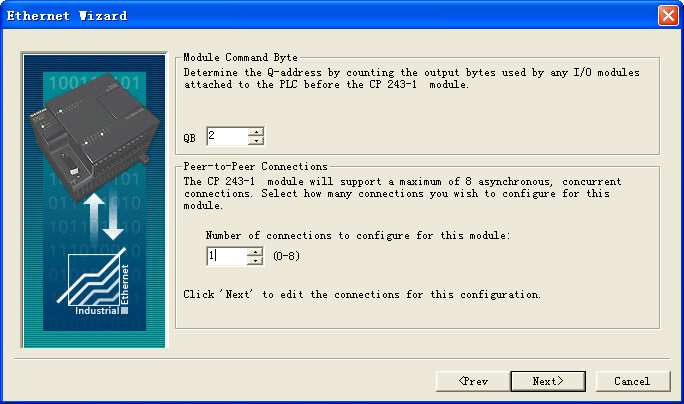 Configure Command Byte and the number of permitted connections.
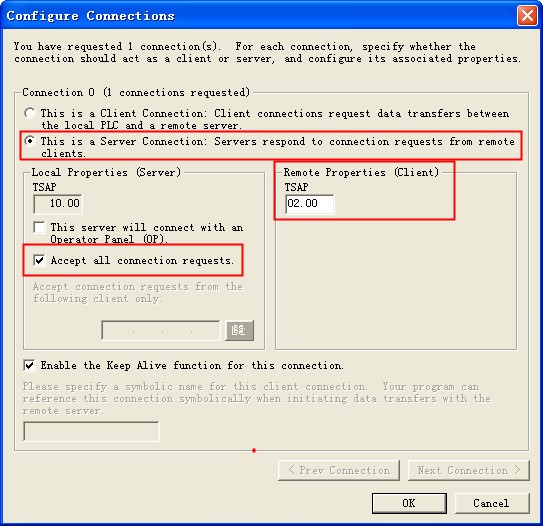 Configure the S7-200 as a TCP server so that the HMI can access it. Configure TSAP and activate that all connections are accepted.
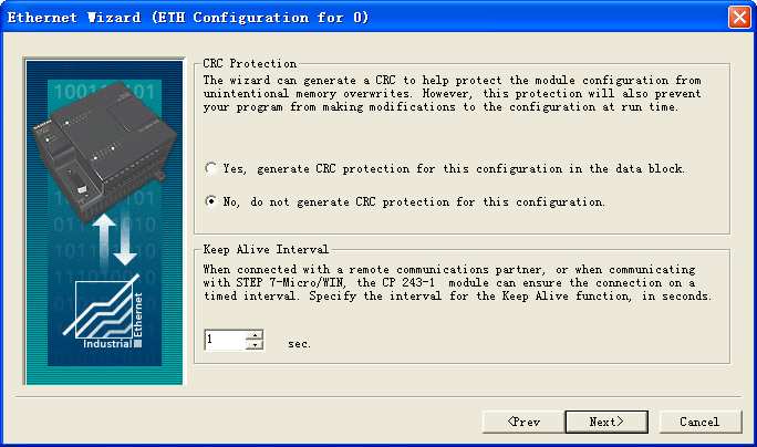 Configure the CRC setting of your choice. CRC should be disabled to test the connection.
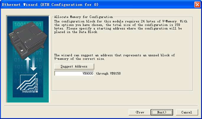 Assign a memory area to the Ethernet configuration. The system suggests an address via "Suggest Address".
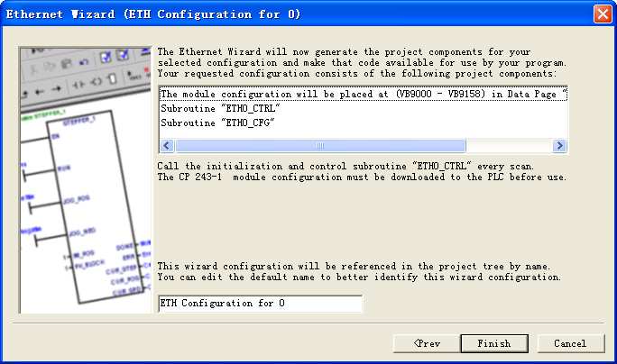 When the configuration is complete, the corresponding data blocks for communication are created in the PLC.
 Important: In your Step 7 program, you must call the ETH0_CTRL subroutine in every cycle for the communication to work.
Addressing the Siemens PLC variables
Kinco HMI elements
Kinco HMIware provides a large selection of elements for visualizing and changing PLC data. These include, for example, switches, lamps, input fields and much more. These elements can be easily linked to variables in the PLC. The variables listed below are available for the Siemens S7-200 via Ethernet.
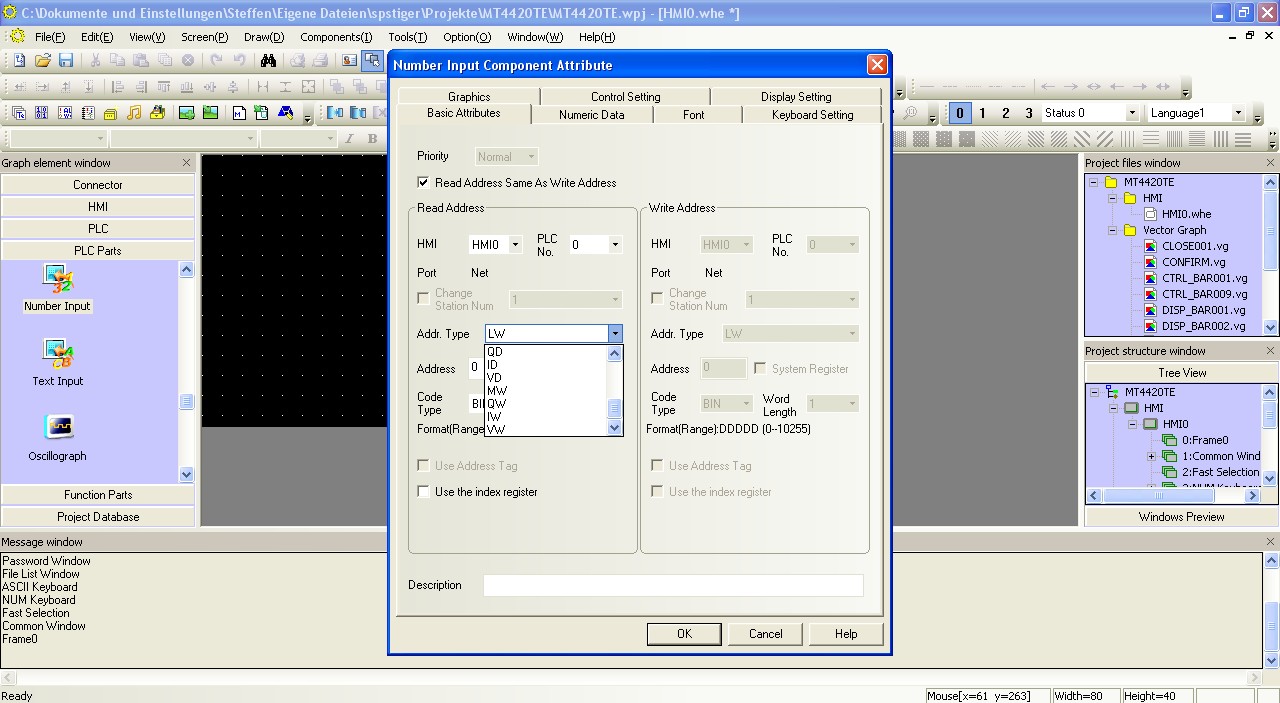 Selecting a variable in an HMI element in the Kinco HMIware
Bit addresses
You can use the following address ranges in the S7-200 via Ethernet to link to bit elements such as switches or lamps:
- Flags (M.B 0.0-31.7)
- Outputs (Q.B 0.0-15.7)
- Inputs (I.B 0.0-15.7)
- Variable memory addressed bit by bit (V.B 0.0-8191.7)
Make sure to use the dot notation for addressing.
Word and double word addresses
You can use the following address ranges in the S7-200 via Ethernet to link to word or double word elements (16-bit or 32-bit) such as input fields, position animations, fill levels, etc.:
- Flag blocks, addressed 16-bit by 16-bit (MW 0-30)
- Flag blocks, addressed 32 bits at a time (MD 0-28)
- Output blocks, addressed 16 bits at a time (QW 0-14)
- Output blocks, addressed 32 bits at a time (QD 0-12)
- Input blocks, addressed 16 bits at a time (IW 0-14)
- Input blocks, addressed 32 bits at a time (ID 0-12)
- Variables, addressed 16 bits at a time (VW 0-8190)
- Variables, addressed 32 bits at a time (VD 0-8188)
Further information on programming the Kinco HMI can be found in our online course
Kinco HMIware online course
-
Serial connection (RS-232 or RS-485)
- Connection
- Driver configuration in Kinco HMIware
- Configuration of the S7-200
- Addressing
Serial connection of the Simatic S7-200 via RS-232 or RS-485
You can easily connect the Simatic S7-200 to the Kinco HMI via a serial interface, either using a programming cable via RS-232 or via a special RS-485 cable. The small 4'' Kinco HMI has one serial port, devices from 6'' have at least two serial ports. All serial interfaces support both RS-232 and RS-485 communication.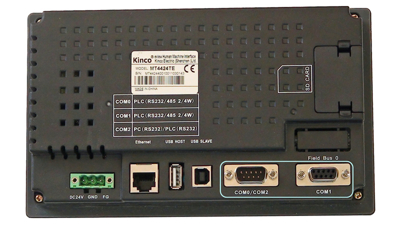 The serial ports of a 7" Kinco MT4424TE HMI support both RS-232 and RS-485 communication
RS-232
RS-232 is a serial communication protocol for a point-to-point direct connection. A Siemens S7-200 can be connected directly to the HMI via RS-232, either directly via programming cable with COM 0 or with larger Kinco HMIs via an adapter with COM 1. All physical ports on the Kinco HMI support RS-232 communication. The physical connection COM 0 has an additional RS-232 connection (COM 2) on pins 7 (Rx) and 8 (Tx). A special serial cable is required to connect this to the Siemens S7-200.
RS-485
RS-485 is a protocol for serial communication with which the Kinco HMI can communicate with several participants via one connection. You can connect several Siemens S7-200s to a Kinco HMI via RS-485. Special serial cables are required for this. Pin assignment of the RS-485 connection cable for the Kinco HMI and the Siemens S7-200
Driver configuration for S7-200 via a serial connection in the Kinco HMIware
The appropriate driver in the Kinco HMIware for connecting the S7-200 PLC via a serial interface is the Siemens S7-200 driver.
All Kinco HMIs can communicate with the Siemens S7-200 via a serial interface. To do this, a project must be created accordingly in the Kinco HMIware, the communication configured and the project transferred to the HMI. The graphical configuration is carried out in the following steps
.- Create a new project in the Kinco HMIware or open an existing project
- Drag the HMI used in the HMI tab into the project
- Under PLC, drag the Siemens S7-200 into the project
- Now open the "Connector" menu and drag a serial connection into the project using "Serial Port"
- Connect the serial connection to COM 0 or COM 1 on the HMI (special cables are required for COM 2)
- Connect the serial connection to COM 0 on the PLC
- Important: Double-click on the PLC to configure the Station Number
- Double-click on the HMI to configure the corresponding serial COM port
- Compile the project and transfer it to the HMI via download
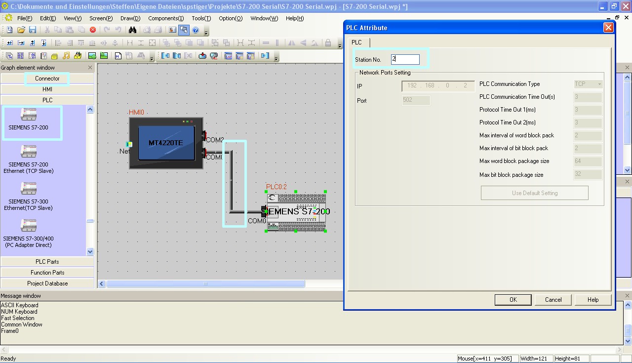 Configuration of the communication between Kinco HMI and Siemens S7-200 via the serial interface in the Kinco HMIware - the configuration of the station number is important
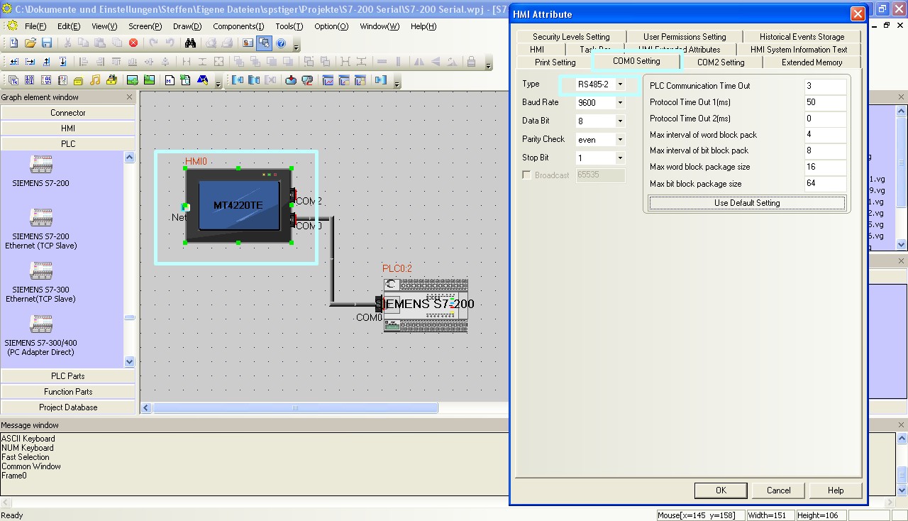 The configuration of the serial interface of the Kinco HMI can be accessed by double-clicking on the HMI. The type of communication (RS-232, RS-485-2, i.e. two-wire or RS-485-4, i.e. four-wire) is configured here. You can also configure the baud rate and other parameters here.
The full version of the programming software for the Kinco HMI can be downloaded here
Kinco HMIware 2.0 (248 MB)
Configuration in the Simatic S7-200
Configure the serial communication in the S7-200 via your Step 7 Micro/WIN software. In particular, make sure that the PLC address in Step 7 and the station number in the Kinco HMIware configuration match.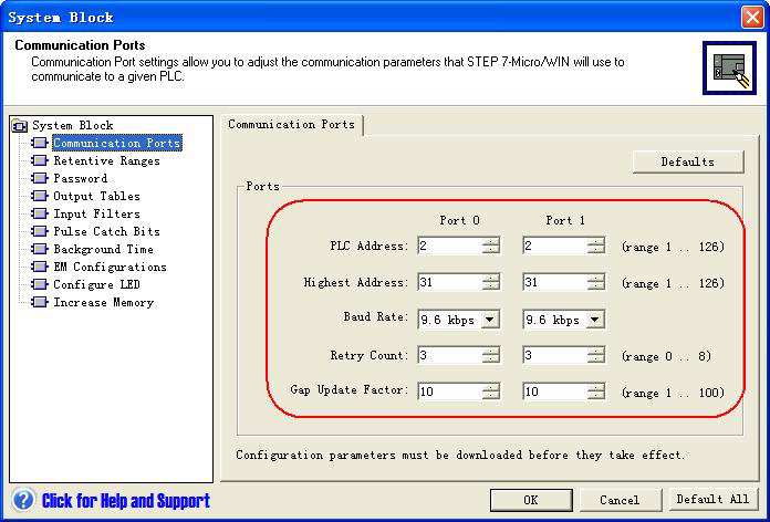 Configuration of the serial interface of the S7-200 in Step 7
Addressing the Siemens PLC variables
Kinco HMI elements
Kinco HMIware provides a large selection of elements for visualizing and changing PLC data. These include, for example, switches, lamps, input fields and much more. These elements can be easily linked to variables in the PLC. For the Siemens S7-200, a very large number of variable areas are available via the serial connection. The exact list of all addressable areas can be found below.
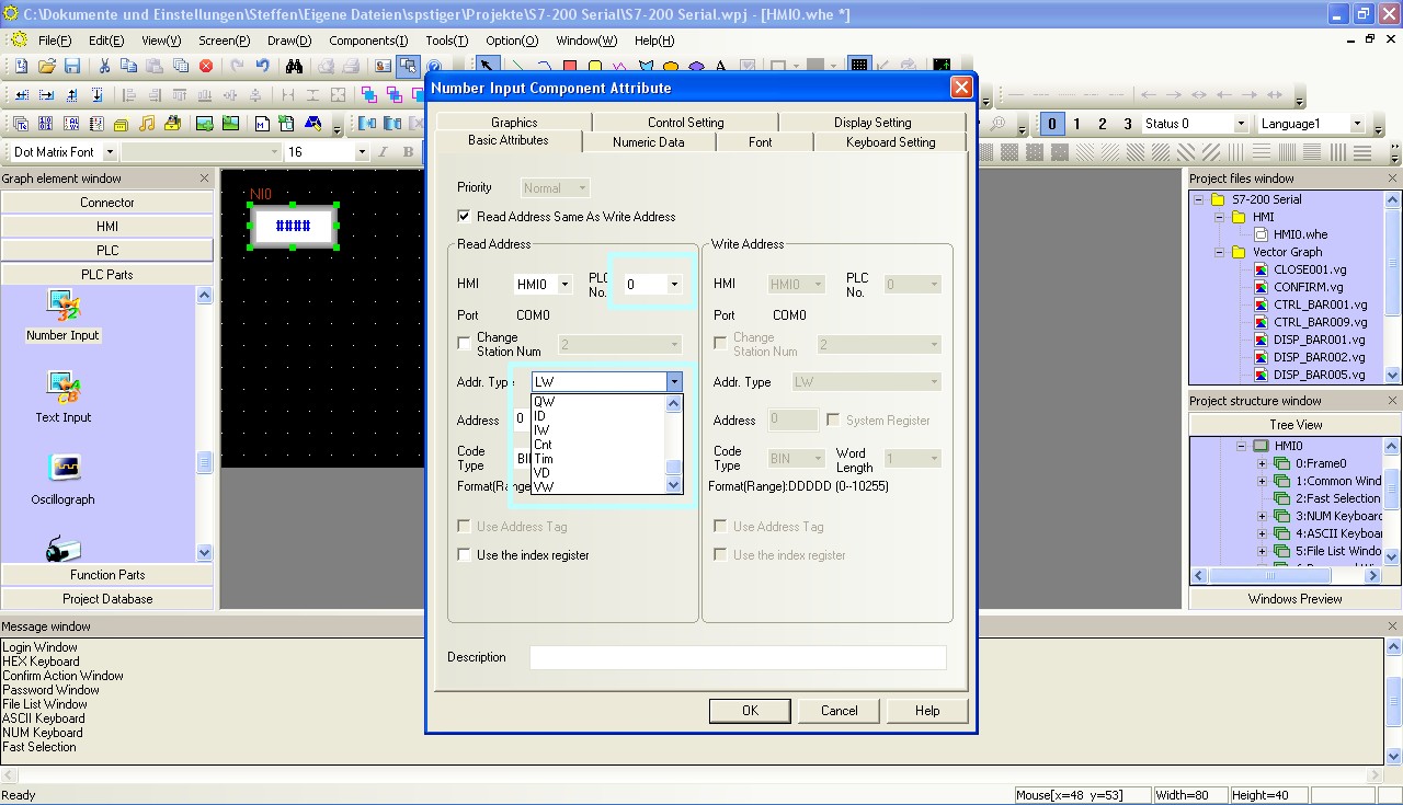 Selection of a variable in an HMI element in the Kinco HMIware
Bit addresses
You can use the following address ranges in the S7-200 via the serial connection to link to bit elements such as switches or lamps:
- Flags (M.B 0.0-31.7)
- Outputs (Q.B 0.0-15.7)
- Inputs (I.B 0.0-15.7)
- Variable memory addressed bit by bit (V.B 0.0-10238.7)
- Counter bits (Cnt 0-255)
- Timer bits (Tim 0-255)
- Special memory addressed bit by bit (SM.B 0.0-549.7)
- SCR [Squence Control Relay] (S.B 0.0-31.7)
Make sure to use the dot notation for addressing.
Word and Double Word addresses
You can use the following address ranges in the S7-200 via the serial connection to link to Word or Double Word elements (16-bit or 32-bit) such as input fields, position animations, fill levels, etc.:
- Flag blocks, addressed 16 bits at a time (MW 0-30)
- Flag blocks, addressed 32 bits at a time (MD 0-28)
- Output blocks, addressed 16 bits at a time (QW 0-14)
- Output blocks, addressed 32 bits at a time (QD 0-12)
- Input blocks, addressed 16 bits at a time (IW 0-14)
- Input blocks, addressed 32 bits at a time (ID 0-12)
- Variables, addressed 16 bits at a time (VW 0-10238)
- Variables, addressed 32 bits at a time (VD 0-10236)
- Analog inputs, 16-bit addressed (AIW 0-62)
- Analog outputs, addressed 16 bits at a time (AQW 0-62)
- Counter values, addressed 16 bits at a time (Cnt 0-255)
- Timer values, addressed 16 bits at a time (Tim 0-255)
- Special memory, addressed 16 bits at a time (SMW 0-548)
- Special memory, addressed 32 bits at a time (SMD 0-546)
- SCR [Sequence Control Relay], addressed 16 bits at a time (SW 0-30)
- SCR [Sequence Control Relay], 32-bit addressed (SD 0-28)
Further information on programming the Kinco HMI can be found in our online course
Kinco HMIware online course
-
-
Simatic S7-300/400 or ET 200
-
Ethernet
- Connection
- Driver configuration in Kinco HMIware (S7-300 or ET 200)
- Driver configuration in Kinco HMIware (Redundant S7-400)
- Addressing
Connection of the Simatic S7-300/400 or ET 200 via Ethernet
The Simatic S7-300/400 or ET 200 modules can be easily connected to the Kinco HMI via Ethernet. The prerequisite is, of course, that the Siemens PLC or I/O has an Ethernet-capable CP. You can connect the PLC either via a direct LAN connection or via a hub or switch. This means that several S7-300s or ET 200s can also be visualized on the Kinco HMI via the LAN.
All Kinco HMIs in our online store have a standard RJ-45 Ethernet connection for this purpose.
 The Ethernet connection of a 7" Kinco MT4424TE HMI
Driver configuration for S7-300 or ET 200 via Ethernet in the Kinco HMIware
The appropriate driver in the Kinco HMIware for connecting the S7-300 PLC and for ET 200 modules via Ethernet is the Siemens S7-300 Ethernet (TCP slave) driver.
All Kinco HMIs with an Ethernet connection can communicate with the Siemens S7-300 or the ET 200 via Ethernet. To do this, a project must be created accordingly in the Kinco HMIware, the communication configured and the project transferred to the HMI. The configuration is carried out in the following steps
.- Create a new project in the Kinco HMIware or open an existing project
- Drag the HMI used in the HMI tab into the project
- Under PLC, drag the Siemens S7-300 Ethernet (TCP Slave) into the project
- Double-click on the PLC, then "Network Device Settings" to open the LAN configuration
- Add the PLC under "Add" and configure the IP of the PLC
- Add the HMI under "Add" and configure the IP of the HMI
- Close all open windows with Ok
- Create screens and objects that are linked to variables in the PLC (more on this under Addressing)
- Compile the project and transfer it to the HMI via download
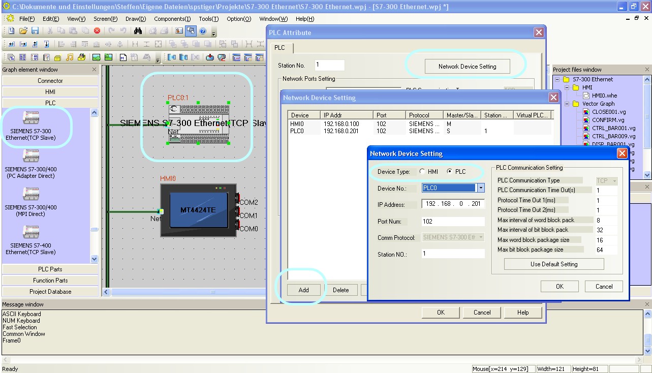 Configure the communication between Kinco HMI and Siemens S7-300 via Ethernet in the Kinco HMIware.
The full version of the programming software for the Kinco HMI can be downloaded here
Kinco HMIware 2.0 (248 MB)
Driver configuration for redundant S7-400 via Ethernet in the Kinco H
MIware
The appropriate driver in the Kinco HMIware for connecting the S7-400 PLC via Ethernet is the Siemens S7-400 Ethernet (TCP Slave) driver.
All Kinco HMIs with Ethernet connection can communicate with the Siemens S7-400 via Ethernet. The special feature of the S7-400 Ethernet driver is that it supports redundant communication with two CPUs.
.
You must create a project accordingly in the Kinco HMIware, configure the communication and transfer the project to the HMI. The configuration is carried out in the following steps- Create a new project in the Kinco HMIware or open an existing project
- Drag the HMI used in the HMI tab into the project
- Under PLC, drag the Siemens S7-400 Ethernet (TCP Slave) into the project
- Double-click on the PLC, then "Network Device Settings" to open the LAN configuration
- Add the PLC under "Add" and configure the IP of the PLC
- Configure the redundant IP of the PLC
- Add the HMI under "Add" and configure the IP of the HMI
- Close all open windows with Ok
- Create screens and objects that are linked to variables in the PLC (more on this under Addressing)
- Compile the project and transfer it to the HMI via download
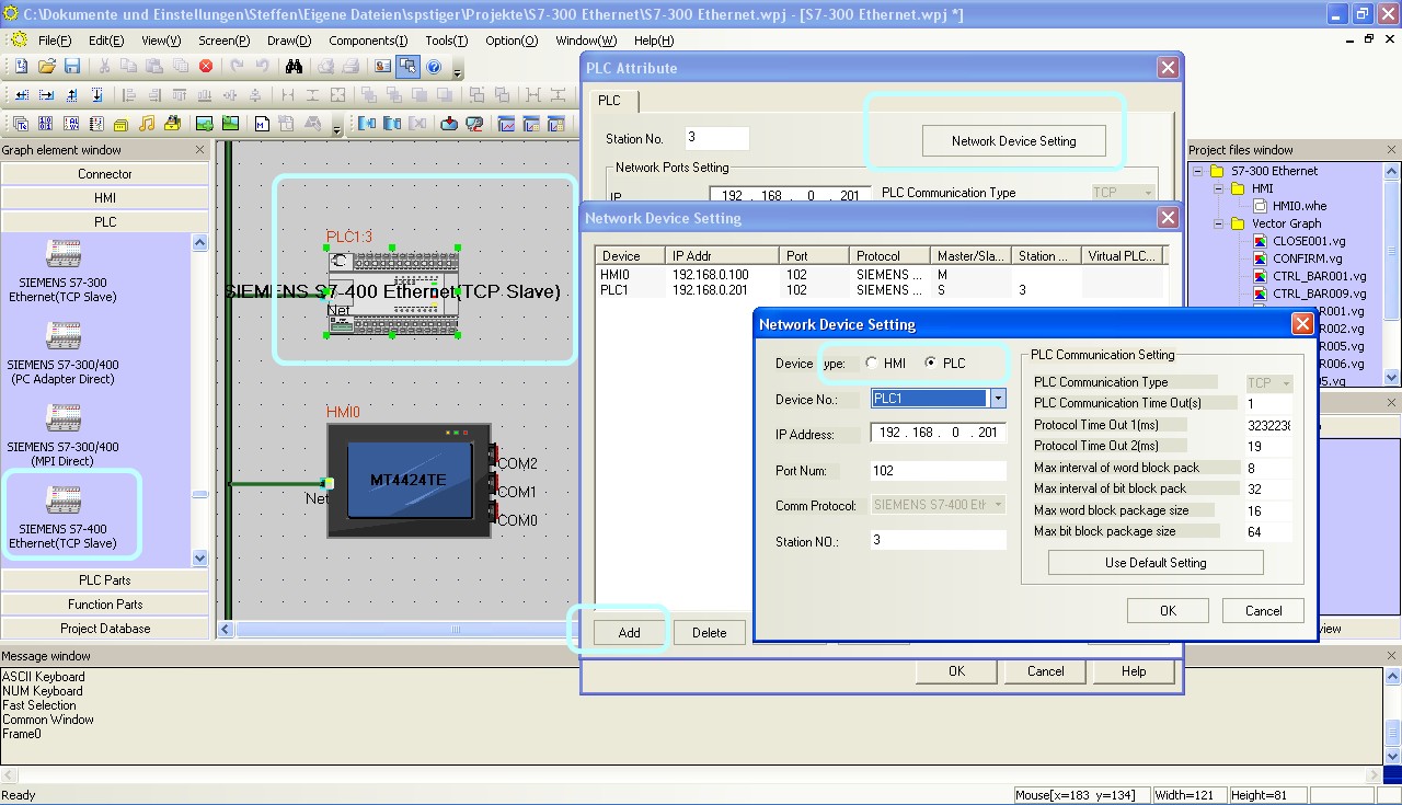 Configure the communication between Kinco HMI and Siemens S7-400 via Ethernet in the Kinco HMIware.
Configuration of the IP and rack numbers
For the redundant connection to the S7-400, you must set two IPs and also the rack and slot numbers of the CPUs in the communication settings of the PLC in the Kinco HMIware. Proceed as follows:- Enter the IP of the first CPU in the IP field
- Enter a combination of rack and slot number under Station Number. Station Number is one byte. The upper 4 bits are the rack number, the lower 4 bits are the slot number. For rack 0 and slot 3, for example, enter 3 (from hex 0x03) in the Station Number field.
- Enter the IP of the second CPU in the "Protocol Timeout 1" field. To do this, convert the IP into a decimal number. If you search the Internet for "IP Decimal Calculator", you will find tools to help you.
- Insert the rack and slot number of the second CPU in the format described above, this time in the "Protocol Timeout 2" field
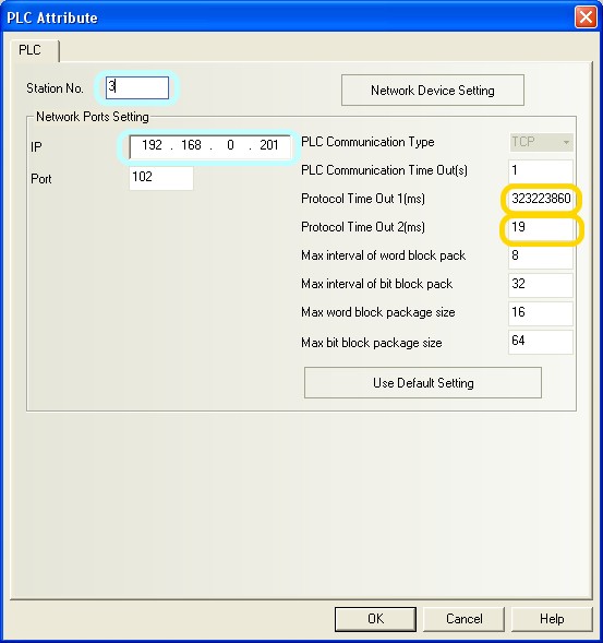 The configuration of redundant communication in Kinco HMIware.
The full version of the programming software for the Kinco HMI can be downloaded here
Kinco HMIware 2.0 (248 MB)
Addressing Siemens PLC variables
Kinco HMI elements
Kinco HMIware provides a large selection of elements for visualizing and changing PLC data. These include, for example, switches, lamps, input fields and much more. These elements can be easily linked to variables in the PLC. The variables listed below are available via Ethernet for the Siemens S7-300/400.
 Selection of a variable in an HMI element in the Kinco HMIware
Bit addresses
You can use the following address ranges in the S7-300/400 or the ET 200 via Ethernet to link to bit elements such as switches or lamps:
- Flags (S7-300: M.B 0.0-2047.7, S7-400: M.B 0.0-8191.7)
- Outputs (S7-300: Q.B 0.0-2047.7, S7-400: Q.B 0.0-255.7)
- Inputs (S7-300: Q.B 0.0-2047.7, S7-400: Q.B 0.0-255.7)
- Bits in data blocks (e.g. DB1_DBX 0.0-65535.7)
Make sure to use the dot notation for addressing.
Word and Double Word addresses
You can use the following address ranges in the S7-300/400 via Ethernet to link to Word or Double Word elements (16-bit or 32-bit) such as input fields, position animations, fill levels, etc.:
- Flag blocks, addressed 16 bits at a time (S7-300: MW 0-2046, S7-400: MW 0-8190)
- Flag blocks, addressed 32 bits at a time (S7-300: MD 0-2044, S7-400: MD 0-8188)
- Output blocks, addressed 16 bits at a time (S7-300: QW 0-2046, S7-400: QW 0-254)
- Output blocks, addressed 32 bits at a time (S7-300: QD 0-2044, S7-400: QD 0-252)
- Input blocks, addressed 16 bits at a time (S7-300: IW 0-2046, S7-400: IW 0-254)
- Input blocks, addressed 32 bits at a time (S7-300: ID 0-2044, S7-400: ID 0-252)
- Data blocks, 16-bit addressed (e.g. DB1_DBW 0-65534)
- Data blocks, addressed 32 bits at a time (e.g. DB1_DBD 0-65532)
larger than 10
Separate address ranges are available for addressing data blocks up to 10. There is a DBn_Dxx area for data blocks larger than 10. Any data blocks can be addressed via this area. The first one to three digits stand for the data block (1..255) and the following five digits for the address of the variable (00001..65536).
Examples:- DBn_DBW with address 100001 is word 1 in data block 1
- DBn_DBW with address 1200012 is Word 12 in data block 12
- DBn_DBW with address 11200318 is Word 318 in data block 112
These DBn address ranges are available for bit (DBn_DBX), word (DBn_DBW) and double word (DBn_DBD) addressing.
Further information on programming the Kinco HMI can be found in our online course
Kinco HMIware online course
-
New: Serial connection MPI point-to-point
- connection
- Driver configuration in Kinco HMIware
- Configuration of the S7-300
- Addressing
Serial connection of the Simatic S7-300/400 via MPI (RS-485) Point
-to-point
You can easily connect the Simatic S7-300/400 to the Kinco HMI via serial interface using MPI (RS-485). A maximum of one PLC can be connected directly to the Kinco HMI via the MPI point-to-point protocol. The small 4'' Kinco HMI has one serial port, devices from 6'' upwards usually have two serial ports. The serial ports of a 7" Kinco MT4424TE HMI support both RS-232 and RS-485 communication
MPI (RS-485)
MPI is a Siemens communication protocol that physically uses the RS-485 serial interface. A Siemens S7-300/400 can be connected directly to the HMI via an MPI point-to-point connection.
 Pin assignment of the RS-232 PC adapter for connecting the Kinco HMI and the Siemens S7-300
Driver configuration for S7-300/400 via MPI (point-to-point) in the Kinco HMIware
The appropriate driver in the Kinco HMIware for connecting the S7-300/400 PLC via direct MPI connection is the Siemens MPI driver.
Kinco HMI can communicate with the Siemens S7-300/400 via MPI (a firmware update may be necessary for this). To set up the communication in Kinco HMIware, create a project accordingly, configure the communication and transfer the project to the HMI. The graphical configuration is carried out in the following steps
.- Create a new project in Kinco HMIware or open an existing project
- Drag the HMI used in the HMI tab into the project
- Under PLC, drag the Siemens MPI into the project
- Now open the "Connector" menu and drag a serial connection into the project using "Serial Port"
- Connect the serial connection to COM 0 or COM 1 on the HMI
- Connect the serial connection to COM 0 on the PLC
- Important: Configure the station number by double-clicking on the PLC
- Double-click on the HMI to configure the corresponding serial COM port
- Compile the project and transfer it to the HMI via download
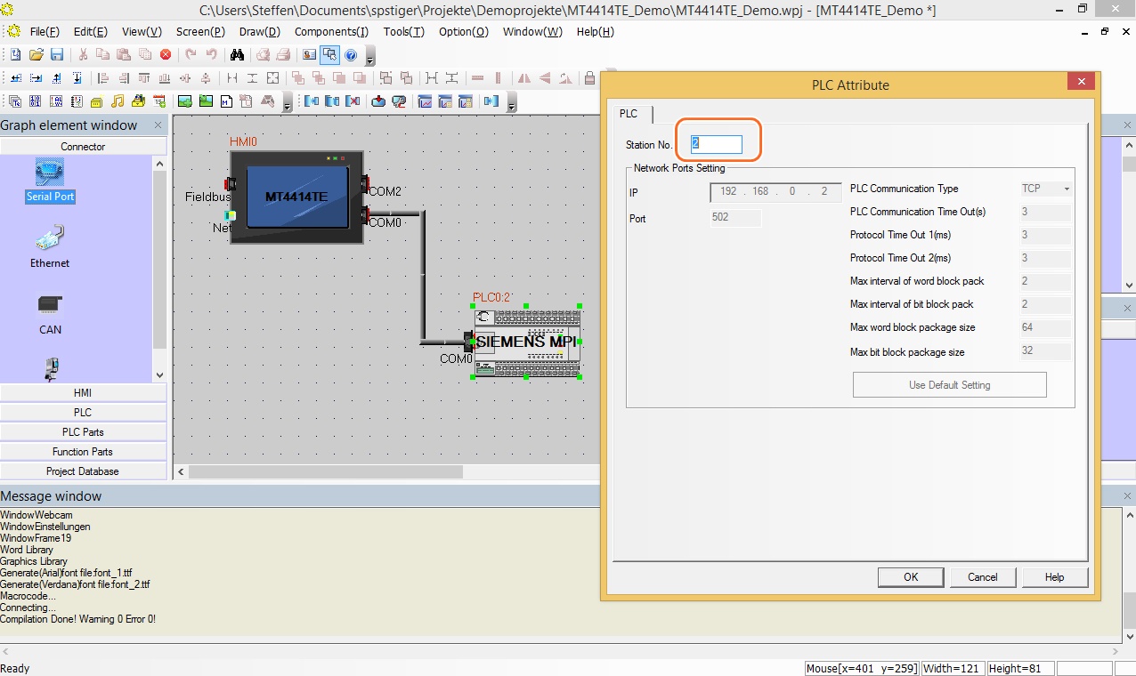 Configuration of the communication between Kinco HMI and Siemens S7-300 via MPI in the Kinco HMIware - the configuration of the station number is important
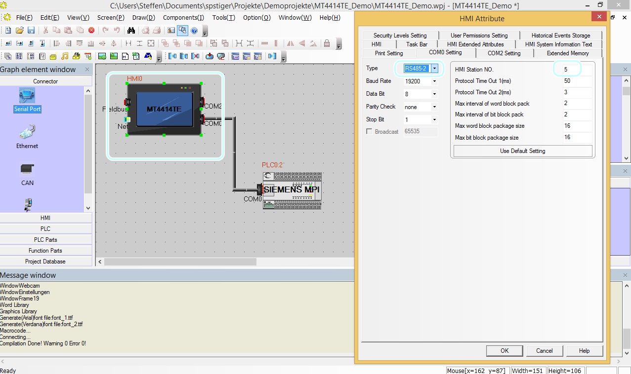 The configuration of the serial interface of the Kinco HMI can be accessed by double-clicking on the HMI. The type of communication (RS-232, RS-485-2, i.e. two-wire or RS-485-4, i.e. four-wire) is configured here. You can also configure the baud rate and other parameters here.
Configuration in the Simatic S7-300/400
Configure the MPI connection for communication in the S7-300 via your Step 7 software. The baud rate of the MPI connection can be 187.5k or 19.2k. The station number of the PLC can be between 2 and 15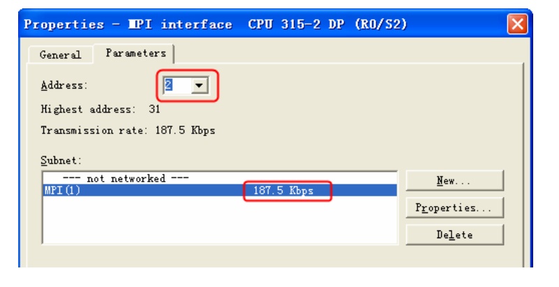 Configuration of the baud rate and station number for Siemens MPI
Addressing the Siemens PLC variables
Kinco HMI elements
Kinco HMIware provides a large selection of elements for visualizing and changing PLC data. These include, for example, switches, lamps, input fields and much more. These elements can be easily linked to variables in the PLC. Selected variable areas are available for the Siemens S7-300/400 via the serial connection. The exact list of all addressable areas can be found below.
 Selection of a variable in an HMI element in the Kinco HMIware
Bit addresses
You can use the following address ranges in the S7-300/400 via the serial connection to link to bit elements such as switches or lamps:
- Flags (M.B 0.0-4095.7)
- Outputs (Q.B 0.0-511.7)
- Inputs (I.B 0.0-511.7)
- Bits in data blocks (e.g. DB1_DBX 0.0-65535.7)
Make sure to use dot notation for addressing.
Word and Double Word addresses
You can use the following address ranges in the S7-300/400 via the serial connection to link to Word or Double Word elements (16-bit or 32-bit) such as input fields, position animations, fill levels, etc.:
- Marker blocks, addressed 16 bits at a time (MW 0-2046)
- Flag blocks, addressed 32 bits at a time (MD 0-2044)
- Output blocks, addressed 16 bits at a time (QW 0-126)
- Output blocks, addressed 32 bits at a time (QD 0-124)
- Input blocks, addressed 16 bits at a time (IW 0-126)
- Input blocks, addressed 32 bits at a time (ID 0-124)
- Data blocks, addressed 16 bits at a time (e.g. DB1_DBW 0-65534)
- Data blocks, addressed 32 bits at a time (e.g. DB1_DBD 0-65532)
larger than 10
Separate address ranges are available for addressing data blocks up to 20. There is a DBn_Dxx area for data blocks larger than 10. Any data blocks can be addressed via this area. The first one to three digits stand for the data block (1..255) and the following five digits for the address of the variable (00001..65536).
Examples:- DBn_DBW with address 100001 is word 1 in data block 1
- DBn_DBW with address 1200012 is Word 12 in data block 12
- DBn_DBW with address 11200318 is Word 318 in data block 112
These DBn address ranges are available for bit (DBn_DBX), word (DBn_DBW) and double word (DBn_DBD) addressing.
Further information on programming the Kinco HMI can be found in our online course
Kinco HMIware online course
-
Serial connection (PC adapter RS-232) only S7-300/400
- Connection
- Driver configuration in Kinco HMIware
- Configuration of the S7-300
- Addressing
Serial connection of the Simatic S7-300/400 via RS-232
You can easily connect the Simatic S7-300/400 to the Kinco HMI via a serial interface. To do this, they can be connected directly via the PC adapter with COM 0 via RS-232. The small 4'' Kinco HMI has one serial port, devices from 6'' have at least two serial ports. The serial ports of a 7" Kinco MT4424TE HMI support both RS-232 and RS-485 communication
RS-232
RS-232 is a serial communication protocol for a point-to-point direct connection. A Siemens S7-300/400 can be connected directly to the HMI via RS-232, either directly via a PC adapter with COM 0 or, with larger Kinco HMIs, via an adapter with COM 1. All physical ports on the Kinco HMI support RS-232 communication. The physical connection COM 0 has an additional RS-232 connection (COM 2) on pins 7 (Rx) and 8 (Tx). A special serial cable is required to connect this to the PC adapter of the Siemens S7-300/400.
 Pin assignment of the RS-232 PC adapter for connecting the Kinco HMI and the Siemens S7-300
RS-485
RS-485 is a protocol for serial communication with several participants. Siemens uses the MPI protocol for serial communication with several participants. The normal serial interfaces of the Kinco HMI do not support MPI.
However, there are special Kinco models that have their own MPI interface.
Driver configuration for S7-300/400 via a serial connection in the Kinco HMIware
The appropriate driver in the Kinco HMIware for connecting the S7-300/400 PLC via serial interface and PC adapter is the Siemens S7-300/400 (PC Adapter Direct) driver.
All Kinco HMIs can communicate with the Siemens S7-300/400 via serial interface and PC adapter. To do this, a project must be created accordingly in the Kinco HMIware, the communication configured and the project transferred to the HMI. The graphical configuration is carried out in the following steps
.- Create a new project in the Kinco HMIware or open an existing project
- Drag the HMI used in the HMI tab into the project
- Under PLC, drag the Siemens S7-300/400 (PC Adapter Direct) into the project
- Now open the "Connector" menu and use "Serial Port" to drag a serial connection into the project
- Connect the serial connection to COM 0 or COM 1 on the HMI (special cables are required for COM 2)
- Connect the serial connection to COM 0 on the PLC
- Important: Configure the Station Number by double-clicking on the PLC
- Double-click on the HMI to configure the corresponding serial COM port
- Compile the project and transfer it to the HMI via download
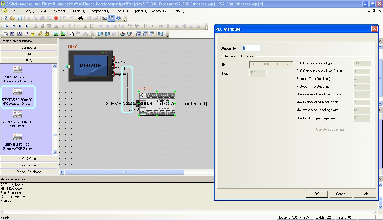 Configuration of the communication between Kinco HMI and Siemens S7-300 via the serial interface in the Kinco HMIware - the configuration of the station number is important
 The configuration of the serial interface of the Kinco HMI can be accessed by double-clicking on the HMI. The type of communication (RS-232, RS-485-2, i.e. two-wire or RS-485-4, i.e. four-wire) is configured here. You can also configure the baud rate and other parameters here. Select the RS-232 type for communication with the PC adapter.
The full version of the programming software for the Kinco HMI can be downloaded here
Kinco HMIware 2.0 (248 MB)
Configuration in the Simatic S7-300
Configure the serial communication in the S7-300 via your Step 7 software. The baud rate between MPI connection and PC adapter should be 187.5k, the baud rate between Kinco HMI and PC adapter 19200.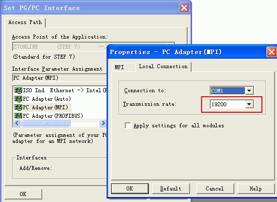 Configuring the baud rate of the PC adapter for communication with the Kinco HMI
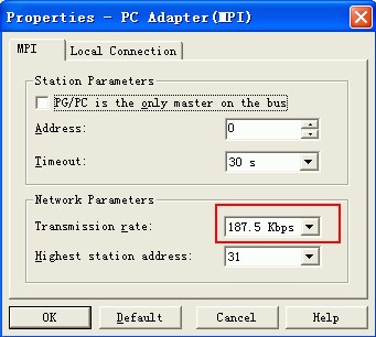 Configuring the baud rate of the PC adapter for communication with the S7-300/400 via MPI
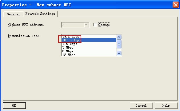 Configuration of the baud rate of the MPI connection for communication with the PC adapter
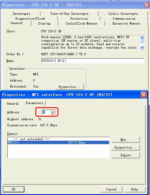 Configuration of the address of the MPI connection for communication with the PC adapter, should be 2
Addressing the Siemens PLC variables
Kinco HMI elements
Kinco HMIware provides a large selection of elements for visualizing and changing PLC data. These include, for example, switches, lamps, input fields and much more. These elements can be easily linked to variables in the PLC. Selected variable areas are available for the Siemens S7-300/400 via the serial connection. The exact list of all addressable areas can be found below.
 Selection of a variable in an HMI element in the Kinco HMIware
Bit addresses
You can use the following address ranges in the S7-300/400 via the serial connection to link to bit elements such as switches or lamps:
- Flags (M.B 0.0-4095.7)
- Outputs (Q.B 0.0-511.7)
- Inputs (I.B 0.0-511.7)
- Bits in data blocks (e.g. DB1_DBX 0.0-65535.7)
Make sure to use dot notation for addressing.
Word and Double Word addresses
You can use the following address ranges in the S7-300/400 via the serial connection to link to Word or Double Word elements (16-bit or 32-bit) such as input fields, position animations, fill levels, etc.:
- Marker blocks, addressed 16 bits at a time (MW 0-2046)
- Flag blocks, addressed 32 bits at a time (MD 0-2044)
- Output blocks, addressed 16 bits at a time (QW 0-126)
- Output blocks, addressed 32 bits at a time (QD 0-124)
- Input blocks, addressed 16 bits at a time (IW 0-126)
- Input blocks, addressed 32 bits at a time (ID 0-124)
- Data blocks, addressed 16 bits at a time (e.g. DB1_DBW 0-65534)
- Data blocks, addressed 32 bits at a time (e.g. DB1_DBD 0-65532)
larger than 10
Separate address ranges are available for addressing data blocks up to 10. There is a DBn_Dxx area for data blocks larger than 10. Any data blocks can be addressed via this area. The first one to three digits stand for the data block (1..255) and the following five digits for the address of the variable (00001..65536).
Examples:- DBn_DBW with address 100001 is word 1 in data block 1
- DBn_DBW with address 1200012 is Word 12 in data block 12
- DBn_DBW with address 11200318 is Word 318 in data block 112
These DBn address ranges are available for bit (DBn_DBX), word (DBn_DBW) and double word (DBn_DBD) addressing.
Further information on programming the Kinco HMI can be found in our online course
Kinco HMIware online course
-


