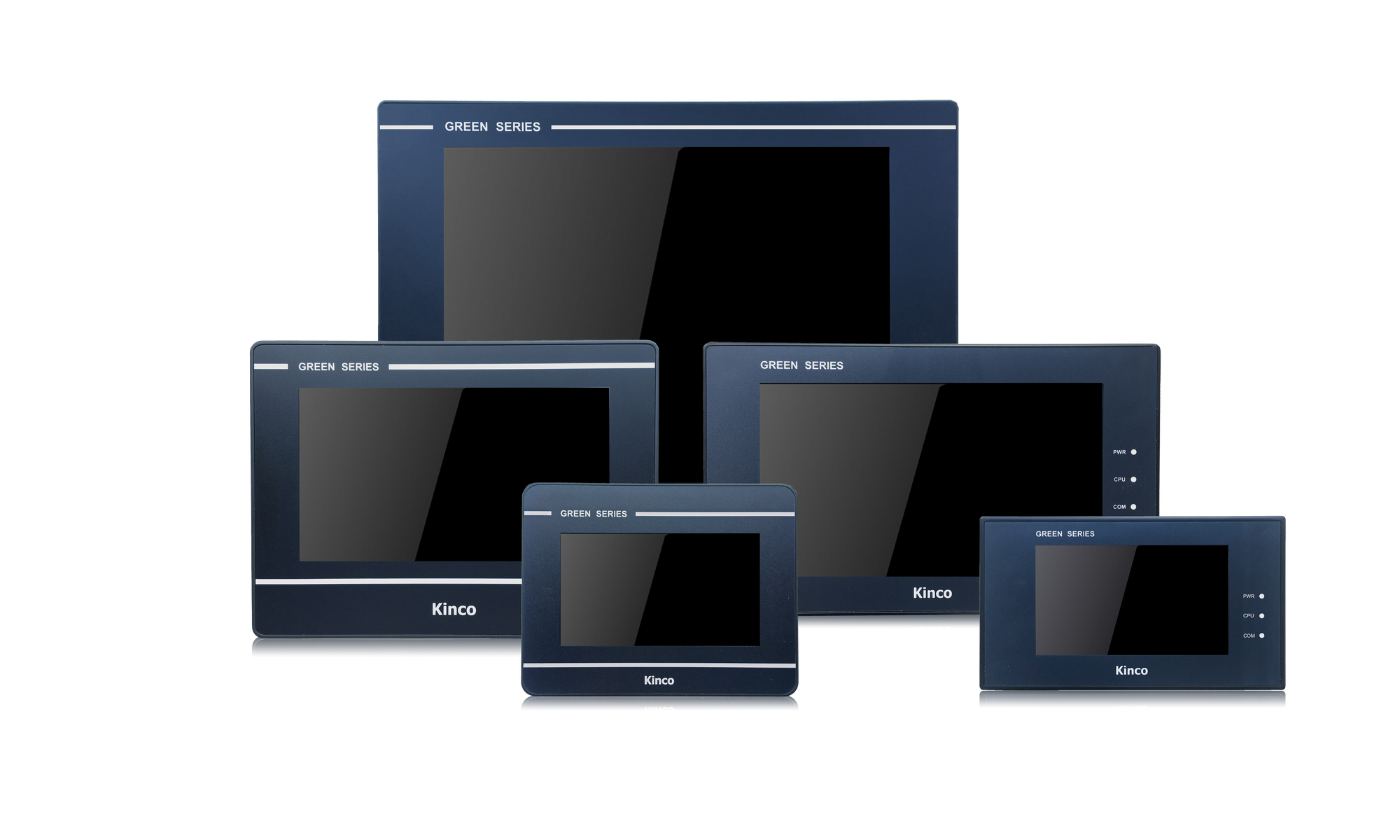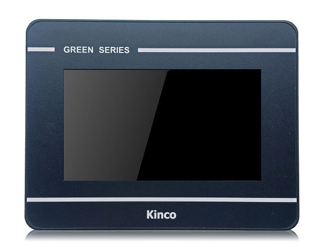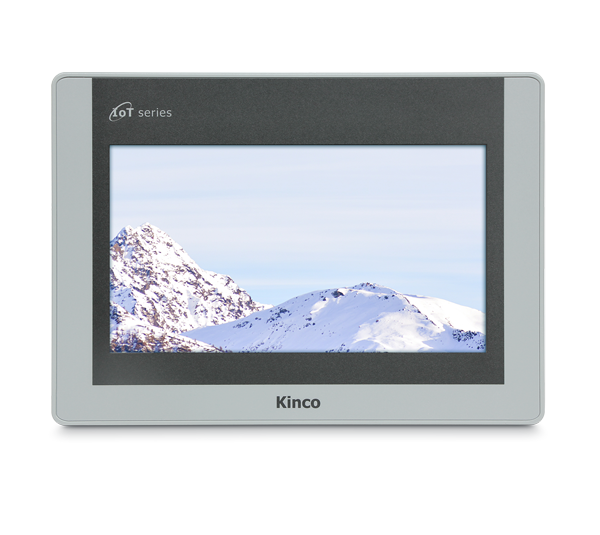
Kinco HMIs are a cost-effective visualization and operating option for Mitsubishi FX and Mitsubishi Q PLCs. Mitsubishi PLCs are very easy to combine with Kinco HMIs. Select your PLC model and the desired connection type to see how the HMI and PLC are connected.
The programming software (German) for the Kinco HMI is completely free of charge. You can download and test it on the respective device.
Below you will find an overview of all Kinco HMIs. Simply select the right size for your visualization project.
Select your PLC model and a connection type
:-
Mitsubishi FX
-
Serial connection (RS-232 or RS-422/RS-485)
- Connection
- Driver configuration in Kinco HMIware
- Configuration of the Mitsubishi FX
- Addressing
Serial connection of the Mitsubishi FX via RS-232 or RS-485
You can easily connect the Mitsubishi to the Kinco HMI via a serial interface, either using a programming cable via RS-232 or via a special RS-485 cable. The small 4'' Kinco HMI has one serial port, devices from 6'' have at least two serial ports. All serial interfaces support both RS-232 and RS-485 communication.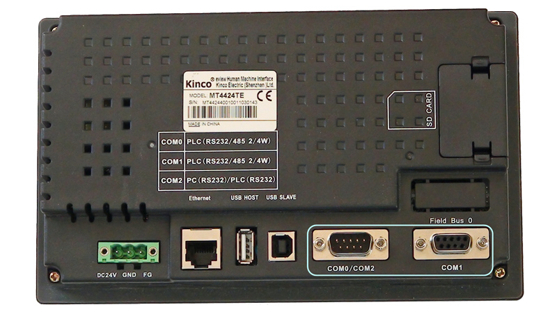 The serial ports of a 7" Kinco MT4424TE HMI support both RS-232 and RS-485 communication
RS-232
RS-232 is a serial communication protocol for a point-to-point direct connection. A Mitsubishi FX can be connected directly to the HMI via RS-232, either directly via a programming cable with COM 0 or, in the case of larger Kinco HMIs, via an adapter with COM 1. All physical ports on the Kinco HMI support RS-232 communication. The physical connection COM 0 has an additional RS-232 connection (COM 2) on pins 7 (Rx) and 8 (Tx). A special serial cable is required to connect this to the Siemens S7-200.
On the Mitsubishi FX, you can connect the touch panel either to the CPU port or to a serial expansion card. The programming cable for the RS-232 extension requires a special cable. Pin assignment of the RS-232 connection cable for the Kinco HMI and the RS-232-BD extension interface of the Mitsubishi FX
RS-485
RS-485 is a protocol for serial communication with which the Kinco HMI can communicate with several participants via one connection. You can connect several Mitsubishi FX to a Kinco HMI via RS-485. Special serial cables are required for this. RS-485 communication also works for RS-422 participants.
You can connect the touch panel to the Mitsubishi FX via RS-485 either at the CPU port or a serial RS-422 or RS-485 expansion card. For communication with several Mitsubishi FX, make sure you select the correct driver in the configuration of the Kinco HMI. For more information, see the Driver configuration tab .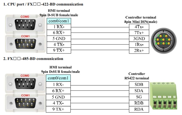 Pin assignment of the RS-422 and RS-485 connection cable for the Kinco HMI and the Mitsubishi FX CPU or serialexpansion card
Driver selection for Mitsubishi FX via a serial connection in the Kinco HMIware
Kinco HMIware offers a wide selection of serial communication drivers for Mitsubishi FX. The following drivers are available:
- Mitsubishi FX-485ADP/485BD/232BD(Multi-station)
- suitable for communication with several Mitsubishi FX PLCs
- requires a Mitsubishi FX serial expansion card
- not suitable for connecting the HMI to the CPU port of the Mitsubishi FX
- Mitsubishi FX1S
- suitable for communication with a Mitsubishi FX1S
- HMI can be connected to the CPU port or to a serial expansion card
- supports RS232, RS-422 and RS-485 communication
- not suitable for connecting multiple Mitsubishi FX to the same HMI serial port
- Mitsubishi FX0N/1N/2N/3G
- suitable for communication with a Mitsubishi FX0N, FX1N, FX1NC, FX2N, FX2NC, FX3G
- HMI can be connected to the CPU port or to a serial expansion card
- supports RS232, RS-422 and RS-485 communication
- not suitable for connecting multiple Mitsubishi FX to the same HMI serial port
- Mitsubishi FX2N_10GM/20GM
- special driver for communication with a Mitsubishi FX2N_10GM or FX2N_20GM
- HMI can be connected to the CPU port
- not suitable for connecting several Mitsubishi FX to the same serial port of the HMI
- Mitsubishi FX3U
- special driver for communication with a Mitsubishi FX3U
- HMI can be connected to the CPU port or to a serial expansion card
- supports RS232, RS-422 and RS-485 communication
- not suitable for connecting multiple Mitsubishi FX to the same serial port of the HMI
Driver configuration in Kinco HMIware
All Kinco HMIs can communicate with the Mitsubishi FX via serial interface. To do this, a project must be created accordingly in Kinco HMIware, the communication configured and the project transferred to the HMI. The graphical configuration is carried out in the following steps
.- Create a new project in the Kinco HMIware or open an existing project
- Drag the HMI used in the HMI tab into the project
- Under PLC, drag the appropriate driver intothe project
- Now open the "Connector" menu and drag a serial connection into the project using "Serial Port"
- Connect the serial connection to COM 0 or COM 1 on the HMI (special cables are required for COM 2)
- Connect the serial connection to COM 0 on the PLC
- to connect additional PLCs, drag another PLC and another serial connection into the project, connect each serial connection to a port on the HMI and the PLC; in the case of the Mitsubishi FX-485ADP/485BD/232BD(Multi-station) driver, one HMI port can accommodate several connections
- Important: Double-click on the PLC to configure the Station Number
- Double-click on the HMI to configure the corresponding serial COM port
- Compile the project and transfer it to the HMI via download
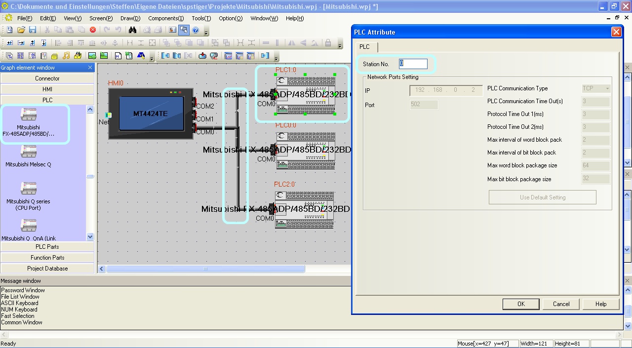 The configuration of the communication between Kinco HMI and PLC via the serial interface in the Kinco HMIware - in the example, several PLCs are connected to the same RS-485 port - the configuration of the station number is important
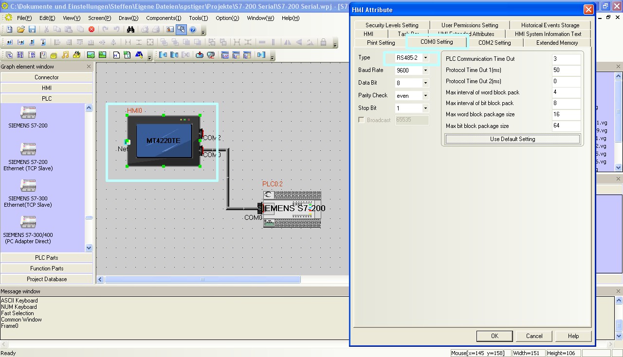 The configuration of the serial interface of the Kinco HMI can be accessed by double-clicking on the HMI. The type of communication (RS-232, RS-485-2, i.e. two-wire or RS-485-4, i.e. four-wire) is configured here. You can also configure the baud rate and other parameters here.
The full version of the programming software for the Kinco HMI can be downloaded here
Kinco HMIware 2.0 (248 MB)
Configuration in the Mitsubishi FX
Configure the serial communication in the Mitsubishi FX via your Mitsubishi software. In particular, make sure that the Station Number in the Mitsubishi PLC and the Station Number in the Kinco HMIware configuration match. The serial communication setting of the Mitsubishi FX-485ADP/485BD/232BD(Multi-station) driver is different from the other drivers. In the case of the multi-station driver, configure the communication according to your connection type. In the case of the other drivers, simply select the default setting of the CPU port or the expansion card.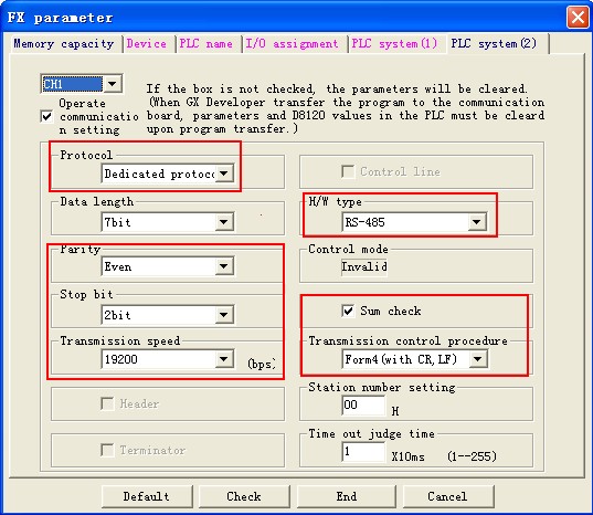 Configuration of the serial interface for the multi-station configuration (Note: For the FX0N, the communication settings are configured in registers D8120, D8121 and D8129)
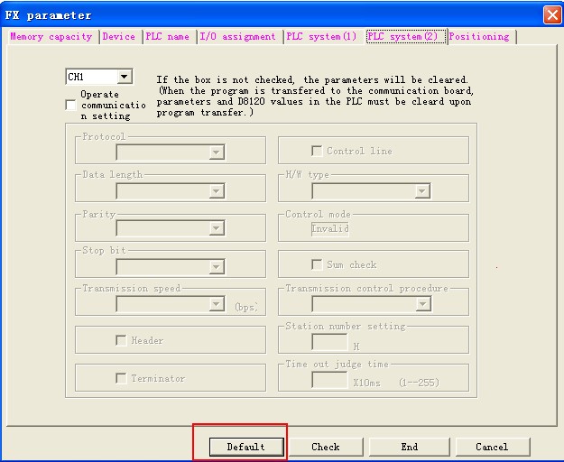 For all direct drivers, you can leave the configuration settings as default.
Addressing the Mitsubishi FX variables
Kinco HMI elements
Kinco HMIware provides a wide range of elements for visualizing and changing PLC data. These include, for example, switches, lamps, input fields and much more. These elements can be easily linked to variables in the PLC. For the Mitsubishi FX, a very large number of variable areas are available via the serial connection. The exact list of all addressable areas can be found below.
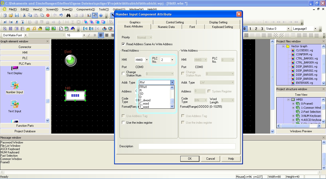 Selection of a variable in an HMI element in the Kinco HMIware
Address overview of the drivers
The various serial Mitsubishi FX drivers in Kinco HMIware support different address ranges:
Address
rangeMitsubishi
FX-485ADP..
(Multi-station)Mitsubishi
FX1SMitsubishi
FX0N/../3GMitsubishi
FX2N_10GM..Mitsubishi
FX3UBits Inputs X 0-571 X 0-764 X 0-377 X 0-571 X 0-764 Outputs Y 0-571 Y 0-764 Y 0-377 Y 0-571 Y 0-764 Marker M 0-7679 M 0-7999 M 0-3071 M 0-7999 M 0-7999 Status-
BitsS 0-4095 S 0-4095 S 0-999 N/A S 0-4095 Counter-
BitsC_bit 0-255 C 0-255 C_bit 0-199 N/A C_bit 0-255 Timer-
BitsT_bit 0-511 T 0-511 T_bit 0-255 N/A T_bit 0-511 System-
BitsSM 8000-8511 N/A SM 8000-8255 SM 9000-9999 SM 8000-8511 Register
Bit-by-bit
addressedN/A D_bit 0.0-7.999.F N/A N/A D_bit 0.0-7.999.F Register Register 16-bit D 0-7999 D 0-17999 D 0-7999 D 0-7999 D 0-17999 System-
Register 16-BitSD 8000-8511 SD 8000-8255 SD 8000-8255 SD 9000-9999 SD 8000-9999 Timer-
value 16-bitT_word 0-511 T_word 0-511 T_word 0-255 N/A T_word 0-511 Counter-
value 16-bitC_word 0-255 C_word 0-199 C_word 0-199 N/A C_word 0-199 Counter-
value 32-bitC_dword 200-255 C_dword 235-255 C_dword 200-255 N/A C_dword 200-255 Extension
Register 16-bitR 0-32767 N/A N/A N/A R 0-32767 FD-
Register 16-BitN/A N/A N/A FD 4000-4550 N/A Current position (system) N/A N/A N/A CP_unit 0-1 N/A FD-
Current position (pulse)N/A N/A N/A CP_pulse 0-1 N/A Further information on programming the Kinco HMI can be found in our online course
Kinco HMIware online course
-
-
Mitsubishi Q
-
Ethernet
- Connection
- Driver configuration in Kinco HMIware
- Configuration of the Mitsubishi Q
- Addressing
Connecting the Mitsubishi Q via Ethernet
The Mitsubishi Q can be easily connected to the Kinco HMI via Ethernet. You can connect the PLC either via a direct LAN connection or via a hub or switch. This means that several Mitsubishi Qs can also be visualized and operated on the Kinco HMI via the LAN.
.
All Kinco HMIs in our online store have a standard RJ-45 Ethernet connection for this purposeOn the Mitsubishi Q side, the HMI is usually connected to a Mitsubishi Ethernet module (QJ71E71). The Mitsubishi Q02UDECPU and Q03UDECPU can also be connected directly via the Ethernet port of the CPU, for which there is a separate driver.
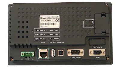 The Ethernet connection of a 7" Kinco MT4424TE HMI
Driver configuration for the Mitsubishi Q via Ethernet in the Kinco HMIware
The appropriate driver in the Kinco HMIware for connecting the Mitsubishi via Ethernet is the Mitsubishi QJ71E71 EtherNet slave driver.
The driver is designed for communication with a QJ71E71 Ethernet module . The Mitsubishi QnA 3EBin Ethernet(TCP Slave) driver is suitable for the direct connection of the Q02UDECPU and Q03UDECPU as well as the L02CPU .All Kinco HMIs with an Ethernet connection can communicate with the Mitsubishi Q via the Ethernet module. To do this, a project must be created accordingly in the Kinco HMIware, the communication configured and the project transferred to the HMI. The configuration is carried out in the following steps
.- Create a new project in the Kinco HMIware or open an existing project
- Drag the HMI used in the HMI tab into the project
- Under PLC, drag the Mitsubishi QJ71E71 EtherNet slave into the project
- Double-click on the PLC, then "Network Device Settings" to open the LAN configuration
- Add the PLC under "Add" and configure the IP of the PLC
- Add the HMI under "Add" and configure the IP of the HMI
- Close all open windows with Ok
- Create screens and objects that are linked to variables in the PLC (more on this under Addressing)
- Compile the project and transfer it to the HMI via download
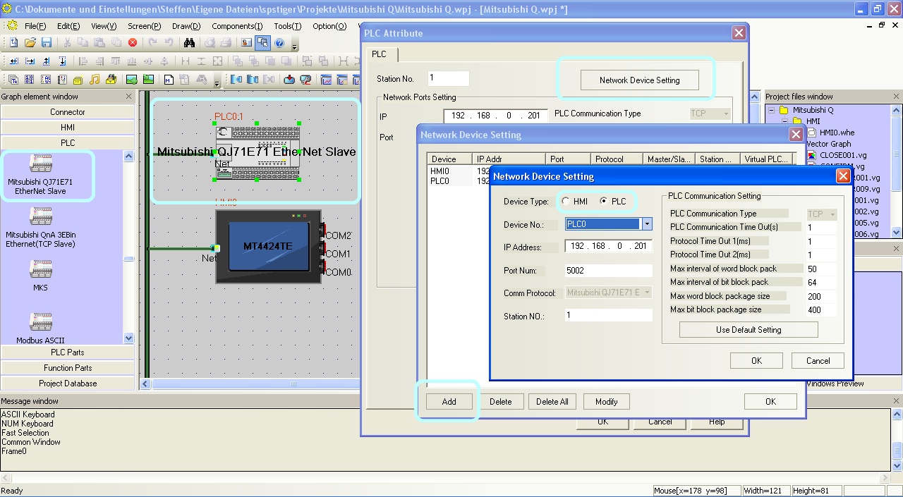 Configure the communication between Kinco HMI and Mitsubishi Q via Ethernet in the Kinco HMIware.
The full version of the programming software for the Kinco HMI can be downloaded here
Kinco HMIware 2.0 (248 MB)
Configuration in the Mitsubishi Q
Configure the Ethernet communication in the Mitsubishi Q via your Mitsubishi software
. In particular, make surethat you enter the IP address of the Kinco HMI in the "Open Settings".
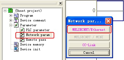 Configuration of the Ethernet extension in the Mitsubishi Q
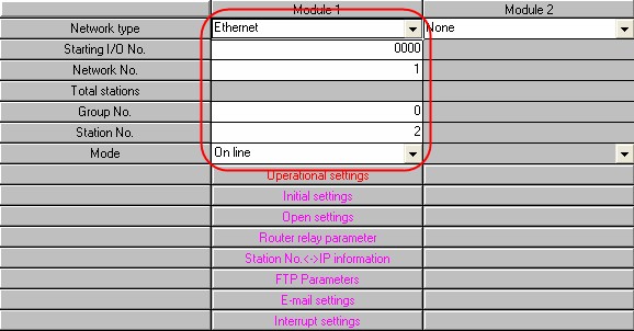 The configuration of the Ethernet module for the Mitsubishi Q
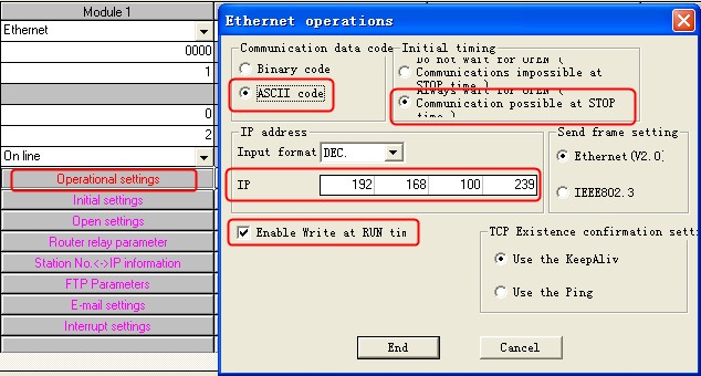 Configuring the IP address and other communication parameters for the Mitsubishi Q
 The configuration of the participants for communication - important: enter the IP of the Kinco HMI here
 Do not forget to transfer the settings of the Ethernet module to the Mitsubishi PLC
Addressing the Mitsubishi Q variables
Kinco HMI elements
Kinco HMIware provides a wide range of elements for visualizing and changing PLC data. These include, for example, switches, lamps, input fields and much more. These elements can be easily linked to variables in the PLC. For the Mitsubishi FX, a very large number of variable areas are available via the Ethernet connection. The exact list of all addressable areas can be found below.
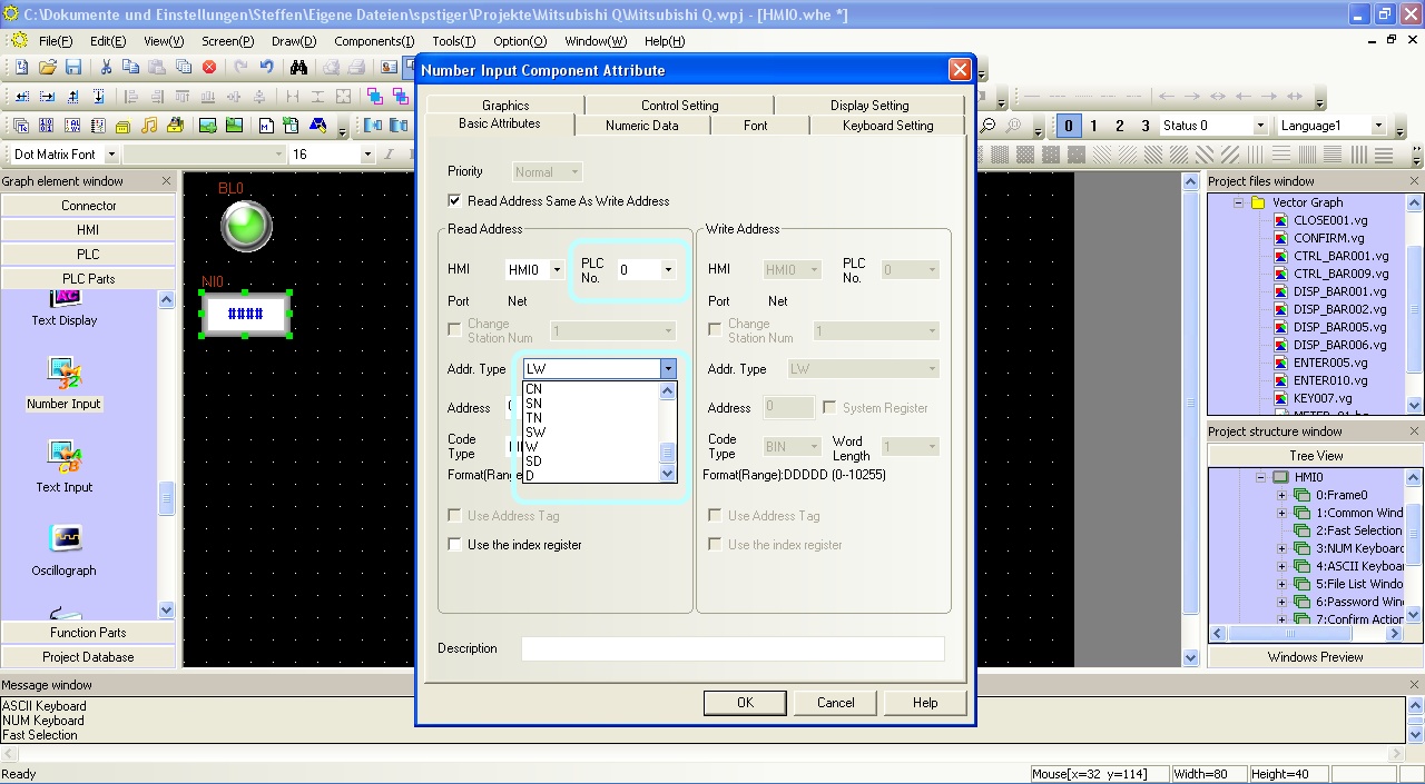 Selection of a variable in an HMI element in the Kinco HMIware
Address overview of the drivers
The two Ethernet drivers for the Mitsubishi Q in Kinco HMIware support different address ranges:
Address range Mitsubishi
QJ71E71 EtherNet SlaveMitsubishi
QnA 3EBin Ethernet(TCP Slave)Bits Inputs X 0-1FFF X 0-1FFF Outputs Y 0-1FFF Y 0-1FFF Marker M 0-32767 M 0-8191 Status bits S 0-8191 S 0-8191 Counter coils CC 0-23087 CC 0-1023 Counter-Contacts CS 0-23087 CS 0-1023 Timer coils TC 0-23087 TC 0-2047 Timer-Contacts TS 0-23087 TS 0-2047 Step-Coils SC 0-23087 SC 0-2047 Step-Contacts SS 0-23087 SS 0-2047 Link relay B 0000-1FFF B 0000-1FFF Special link relay SB 0-7FFF SB 0-7FFF Edge relay V 0-32767 V 0-2047 Latch relay L 0-32767 L 0-8191 Signal relay F 0-32767 F 0-2047 Direct input N/A DX 0-1FFF Direct output N/A DY 0-1FFF System bits SM 0-2047 SM 0-2047 Register Register 16-bit D 0-25983 D 0-45055 System register 16-bit SD 0-2047 SD 0-2047 Timer value 16-bit TN 0-23087 TN 0-2047 Remanent timer value 16-bit SN 0-23087 SN 0-2047 Counter value 16-bit CN 0-23087 CN 0-1023 Link register 16-bit W 0-291F W 0-1FFF Special link register 16-bit SW 0-7FF SW 0-7FF File register 16-bit R 0-32767 R 0-32767 Extended file register 16-bit ZR 0-1042431 ZR 0-393216 Index register 16-bit N/A Z 0-19 Input blocks 16-bit N/A X 0-1FFF Output blocks 16-bit N/A Y 0-1FFF Link blocks 16-bit N/A B 0-1FFF Special link blocks 16-bit N/A SB 0-1FFF Further information on programming the Kinco HMI can be found in our online course
Kinco HMIware online course
-
Serial connection (RS-232 or RS-485)
- Connection
- Driver configuration in Kinco HMIware
- Configuration of the Mitsubishi Q
- Addressing
Serial connection of the Mitsubishi Q via RS-232 or RS-485
You can easily connect the Mitsubishi Q to the Kinco HMI via a serial interface. You can connect it directly to the serial port on the CPU or to a serial RS-232 or RS-485 expansion module. The small 4'' Kinco HMI has one serial port, devices from 6'' have at least two serial ports. The serial ports of a 7" Kinco MT4424TE HMI support both RS-232 and RS-485 communication
RS-232
RS-232 is a serial communication protocol for a point-to-point direct connection. RS-232 can be used to connect a Mitsubishi Q directly to the HMI, either directly on the CPU port or via an RS-232 serial expansion module (C24). All physical ports on the Kinco HMI support RS-232 communication. The physical port COM 0 has an additional RS-232 connection (COM 2) on pins 7 (Rx) and 8 (Tx). A special serial cable is required to connect this to the Mitsubishi Q.
 Pin assignment of the RS-232 connection forconnecting the Kinco HMI and the Mitsubishi Q to the CPU port
 Pin assignment of the RS-232 connection for connecting the Kinco HMI and the Mitsubishi Q02U to the CPU port
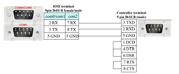 Pin assignment of theRS-232 connector for connecting the Kinco HMI and a Mitsubishi C24 expansion module
RS-485
RS-485 is a protocol for serial communication with several participants. The Mitsubishi Q can communicate with the HMI via this protocol using an RS-485 expansion module (C24). This allows several Mitsubishi Q PLCs to be connected to one serial Kinco connection. You need a special cable for this. Pin assignment of the RS-485 connection for connecting the Kinco HMI and a Mitsubishi C24expansionmodule
Driver selection for Mitsubishi Q via a serial connection in the Kinco HMIware
Kinco HMIware offers a wide selection of serial communication drivers for Mitsubishi Q. The following drivers are available:
- Mitsubishi Q_QnA (Link Port)
- suitable for communication with the following CPUs: Q00jCPU, Q00CPU, Q01CPU, Q02CPU, Q02HCPU, Q12HCPU, Q25HCPU, Q00UJCPU
- suitable for communication with a serial C24 module
- suitable for communication via the CPU port of the following CPUs: Q00CPU, Q01CPU, Q00UJCPU
- suitable for communication via RS-232 or RS-485
- Mitsubishi Melsec Q
- suitable for communication with the following CPUs: Q00jCPU, Q00CPU, Q01CPU, Q02CPU, Q02HCPU, Q12HCPU, Q25HCPU, Q02UCPU
- suitable for communication with a serial C24 module
- suitable for communication via the CPU port of the following CPUs: Q00CPU, Q01CPU, Q02UCPU
- suitable for communication via RS-232 or RS-485
- slower than the Mitsubishi Q_QnA (link port)
- Mitsubishi Q series (CPU Port)
- suitable for communication with the following CPUs Q00jCPU, Q Q02CPU, Q02HCPU, Q12HCPU, Q25HCPU
- HMI is connected to the CPU port
- Supports RS232 communication
- Mitsubishi Q00J (CPU port)
- special driver for communication with a Mitsubishi Q00J CPU via the CPU port
- Mitsubishi Q06H
- Special driver for communication with a Mitsubishi Q06H CPU via the CPU port
Driver configuration in Kinco HMIware
All Kinco HMIs can communicate with the Mitsubishi Q via serial interface. To do this, a project must be created accordingly in Kinco HMIware, the communication configured and the project transferred to the HMI. The graphical configuration is carried out in the following steps
.- Create a new project in the Kinco HMIware or open an existing project
- Drag the HMI used in the HMI tab into the project
- Under PLC, drag the appropriate driver intothe project
- Now open the "Connector" menu and drag a serial connection into the project using "Serial Port"
- Connect the serial connection to COM 0 or COM 1 on the HMI (special cables are required for COM 2)
- Connect the serial connection to COM 0 on the PLC
- to connect additional PLCs, drag another PLC and another serial connection into the project, connect each serial connection to a port on the HMI and the PLC; in the case of the Mitsubishi FX-485ADP/485BD/232BD(Multi-station) driver, one HMI port can accommodate several connections
- Important: Double-click on the PLC to configure the Station Number
- Double-click on the HMI to configure the corresponding serial COM port
- Compile the project and transfer it to the HMI via download
 The configuration of the communication between Kinco HMI and PLC via the serial interface in the Kinco HMIware - in the example, several PLCs are connected to the same RS-485 port - the configuration of the station number is important
 The configuration of the serial interface of the Kinco HMI can be accessed by double-clicking on the HMI. The type of communication (RS-232, RS-485-2, i.e. two-wire or RS-485-4, i.e. four-wire) is configured here. You can also configure the baud rate and other parameters here.
The full version of the programming software for the Kinco HMI can be downloaded here
Kinco HMIware 2.0 (248 MB)
Configuration in the Mitsubishi Q
Configure the serial communication in the Mitsubishi Melsec Q via your Mitsubishi Melsec software.
CPU Port
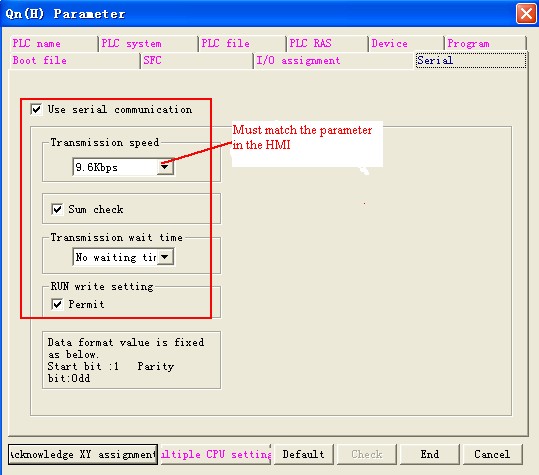 Configuration of the baud rate of the CPU port of the Mitsubishi Q for communication with the Kinco HMI
C24 modules
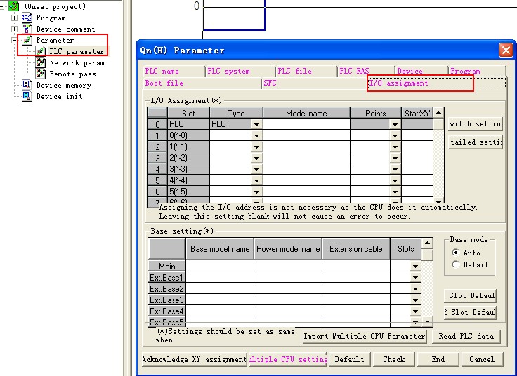 Calling up the I/O assignment
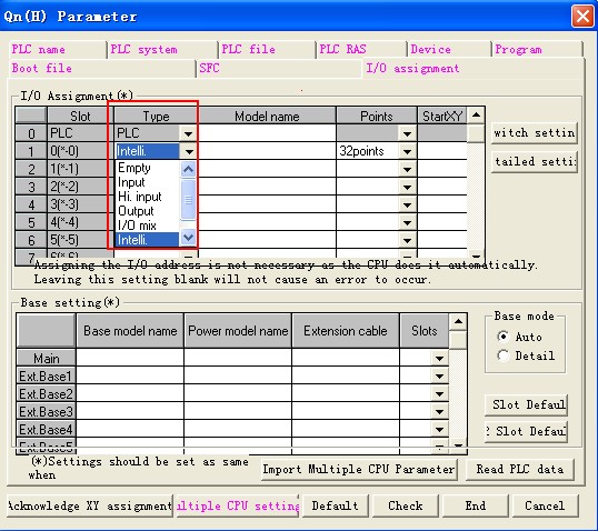 Select "Intelligent"
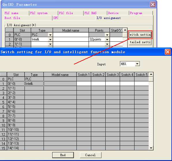 Click on "Switch Setting"
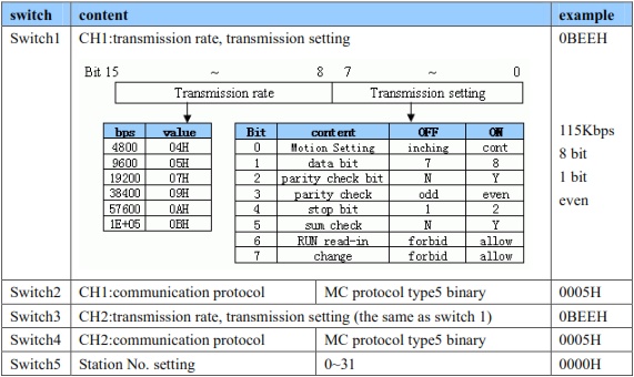 Configure the communication parameters according to your setting in the Kinco HMIware - transfer the setting to the PLC and restart the PLC
Addressing the Mitsubishi Q variables
Kinco HMI elements
Kinco HMIware provides a wide range of elements for visualizing and changing PLC data. These include, for example, switches, lamps, input fields and much more. These elements can be easily linked to variables in the PLC. Many variable areas are available for the Mitsubishi Q via the serial connection. The exact list of all addressable areas can be found below.
 Selection of a variable in an HMI element in the Kinco HMIware
The address ranges of the various serial drivers for Mitsubishi Melsec Q:
Address
rangeMitsubishi
Q_QnA
(Link Port)Mitsubishi
Melsec QMitsubishi
Q series (
CPU Port)Mitsubishi
Q00J
(CPU Port)Mitsubishi
Q06HBits Inputs X 0-1FFF X 0-7FF X 0-1FFF X 0-1FFF X 0-1FFF Outputs Y 0-1FFF Y 0-7FF Y 0-1FFF Y 0-1FFF Y 0-1FFF Marker M 0-32767 M 0-8191 M 0-32767 M 0-32767 M 0-32767 Status bits N/A S 0-2047 N/A S 0-1FFF N/A Counter coils N/A CC 0-511 N/A CC 0-1023 N/A Counter-Contacts N/A CS 0-511 N/A CS 0-1023 N/A Timer coils N/A TC 0-511 N/A TC 0-2047 N/A Timer-Contacts N/A TS 0-511 N/A TS 0-2047 N/A Step-Coils N/A SC 0-511 N/A N/A N/A Step-Contacts N/A SS 0-511 N/A N/A N/A Link relay B 0-7FFF B 0-7FF B 0-7FFF B 0-7FFF B 0-7FFF Special link relay SB 0-7FFF SB 0-7FFF SB 0-7FFF SB 0-7FFF SB 0-7FFF Edge relay V 0-32767 V 0-1023 V 0-32767 V 0-32767 V 0-32767 Latch relay L 0-32767 L 0-2047 L 0-32767 L 0-32767 L 0-32767 Signal relay F 0-32767 F 0-1023 F 0-32767 F 0-32767 F 0-32767 Direct input N/A DX 0-7FF N/A N/A N/A Direct output N/A DY 0-7FF N/A N/A N/A System bits SM 0-2047 N/A SM 0-2047 SM 0-2047 SM 0-2047 Register Register 16-bit D 0-25983 D 0-11135 D 0-25983 D 0-25983 D 0-25983 System register 16-bit SD 0-2047 SD 0-2047 SD 0-2047 SD 0-2047 SD 0-2047 Timer value 16-bit TN 0-23087 TN 0-511 TN 0-23087 TN 0-23087 TN 0-23087 Remanent timer value 16-bit SN 0-23087 SN 0-511 N/A SN 0-2047 N/A Counter value 16-bit CN 0-23087 CN 0-511 CN 0-23087 CN 0-23087 CN 0-23087 Link register 16-bit W 0-291F W 0-1FFF W 0-291F W 0-291F W 0-291F Special link register 16-bit SW 0-7FF SW 0-3 SW 0-7FF SW 0-7FF SW 0-7FF File register 16-bit R 0-32767 R 0-32767 R 0-32767 R 0-32767 R 0-32767 Extended file register 16-bit ZR 0-65535 ZR 0-65535 N/A N/A N/A Index register 16-bit N/A Z 0-9 N/A N/A N/A Further information on programming the Kinco HMI can be found in our online course
Kinco HMIware online course
-


