Filter
–
Kinco offers HMIs with their own CANopen slave interface. This makes it easy to integrate the HMI into a CANopen network and to operate and visualize CANopen devices.
-
CANopen
-
Kinco HMI as CANopen slave
- Connection
- Driver configuration in Kinco HMIware
- Addressing
Connecting the Kinco HMI to a CANopen network
For the connection, you need a Kinco HMI with CANopen slave interface. This interface is designed in addition to the serial interfaces and a possible Ethernet interface.
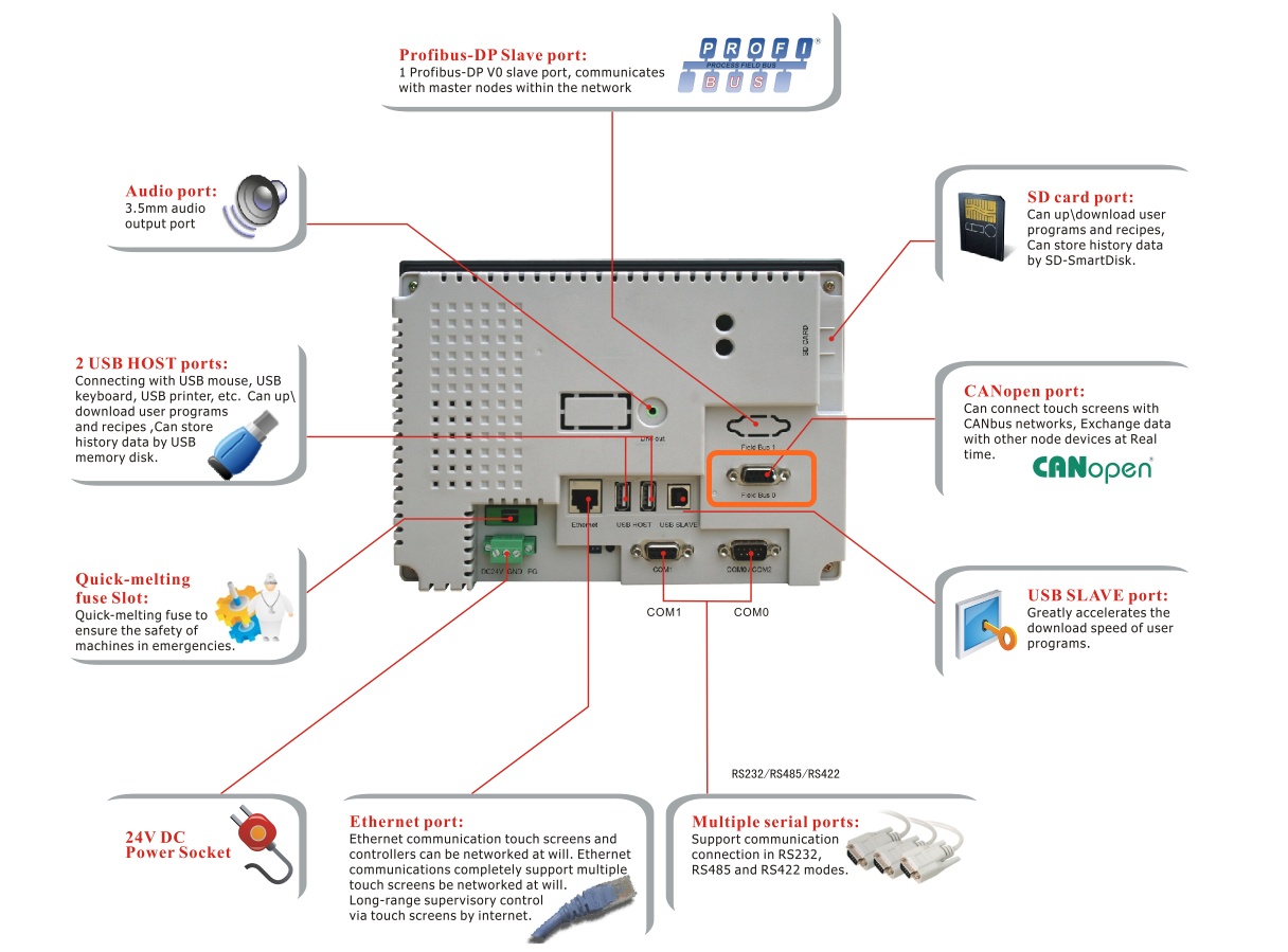 CANopen interface of a Kinco HMI
Driver configuration for CANopen in the Kinco HMIware
To configure your Kinco HMI as a CANopen device, carry out the following steps in the Kinco HMIware:t. Double-click to open the configuration of the HMI and select Fieldbus.- Create a new project in Kinco DTools or open an existing project
- Drag an HMI that supports CANopen into your project
- Double-click to open the configuration of the HMI and select Fieldbus Setting
- Add the HMI under "Add" and configure the protocol as CANopen and the node ID of the HMI
- Close all open windows with Ok
- Create screens and objects that are linked to variables in the PLC (more on this under Addressing)
- Compile the project and transfer it to the HMI via download
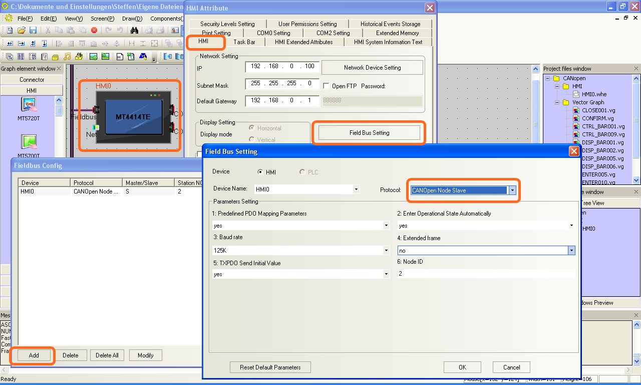 The configuration of a Kinco HMI as a CANopen participant. Also make sure you have the correct node ID.
Addressing the internal variables and configuring the PDO
Kinco HMI elements
Kinco HMIware provides a wide range of elements for visualizing and changing PLC data. These include, for example, switches, lamps, input fields and much more.
For operation as a CANopen slave, these elements are linked to internal variables of the HMI. The CANopen masters can then access these variables themselves as PDOs and read or write them.
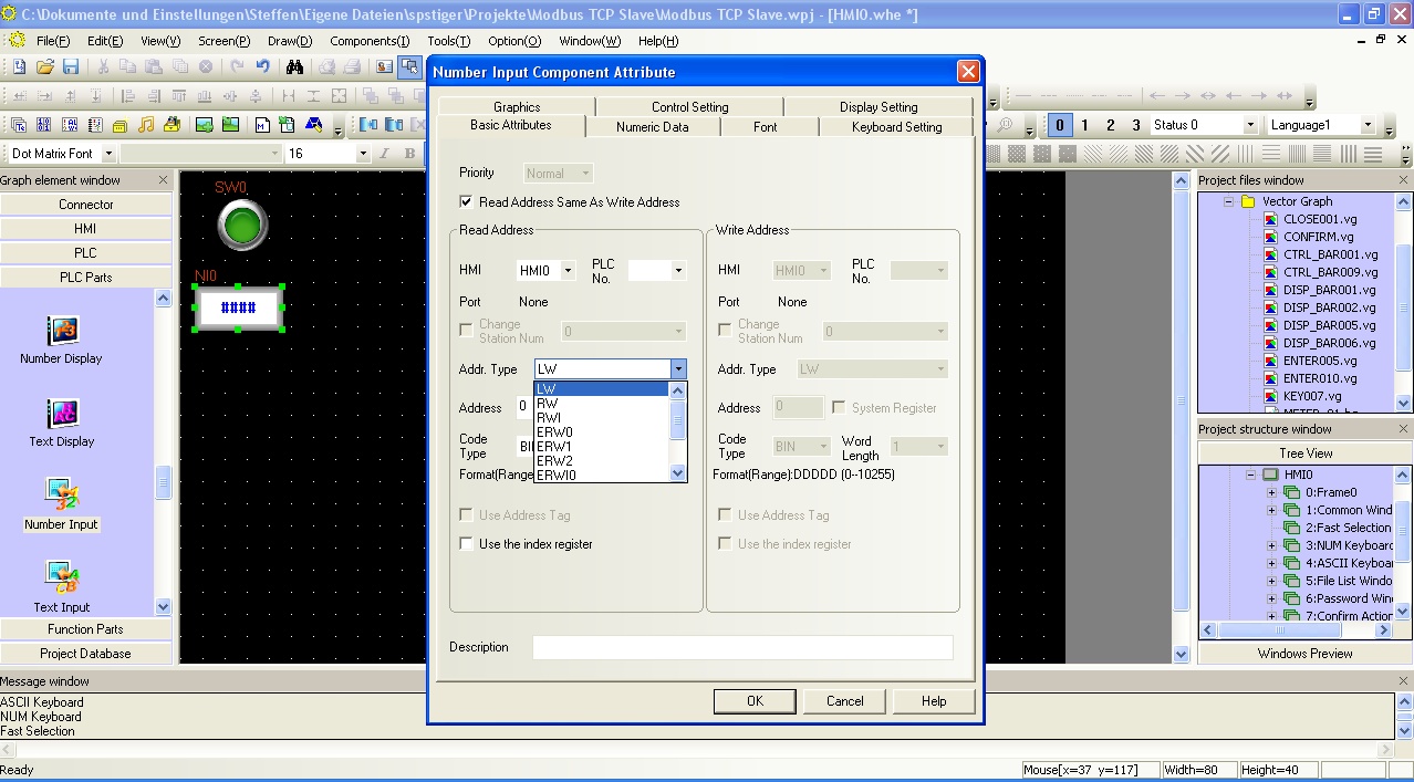 Selection of an internal variable in an HMI element in the Kinco HMIware
Address overview of the PDO standard mapping
There is a standard mapping of the internal variables to the PDO for the Kinco HMI. This looks as follows:
Address rangeKinco addressCANopen PDO Receive PDOs Register 16 Bit LW 8000-8003 PDO 0x1400 (Id: $NodeID+0x200) LW 8004-8007 PDO 0x1401 (Id: $NodeID+0x300) LW 8008-8011 PDO 0x1402 (Id: $NodeID+0x400) LW 8012-8015 PDO 0x1403 (Id: $NodeID+0x500) Send PDOs Register 16 Bit LW 8016-8019 PDO 0x1800 (Id: $NodeID+0x180) LW 8020-8023 PDO 0x1801 (Id: $NodeID+0x280) LW 8024-8027 PDO 0x1802 (Id: $NodeID+0x380) LW 8028-8031 PDO 0x1803 (Id: $NodeID+0x480)
Custom PDO mappings with the PDO manager
In addition to the standard mapping, it is also possible to create your own mapping via the Kinco PDO Manager and transfer it to the HMI.
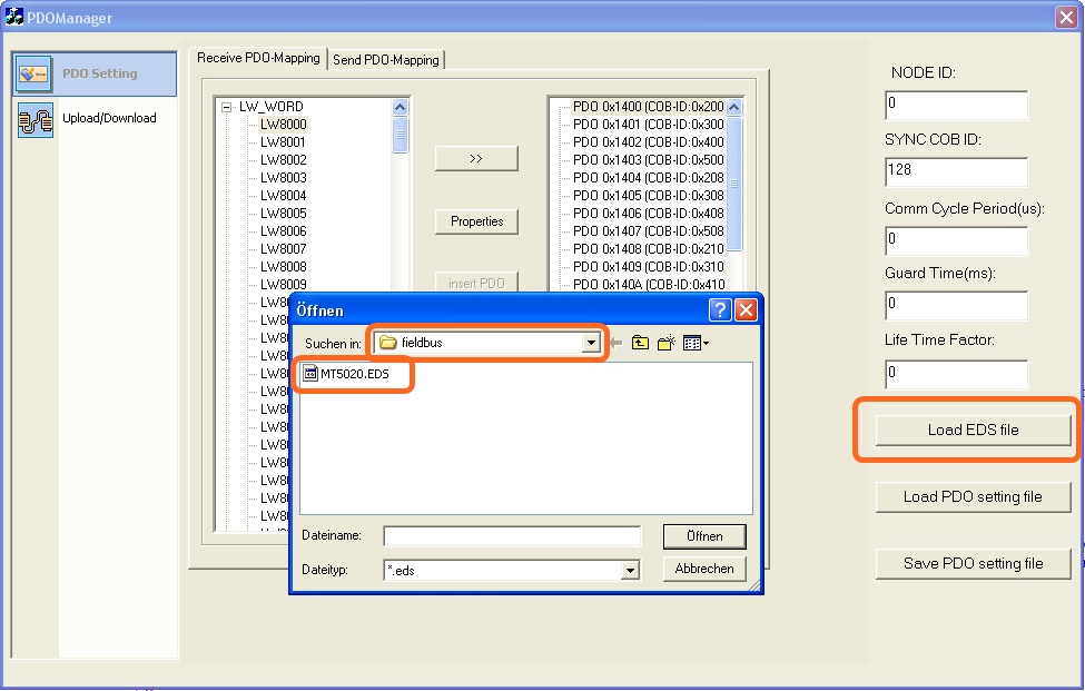 You can find the PDO Manager in the start menu in the Kinco "Tools" directory. Open the supplied EDS file. This can be found in the Kinco installation folder in the "fieldbus" directory. Alternatively, you can also upload the EDS configuration from the Kinco HMI. Then adapt the PDO configuration to your requirements.
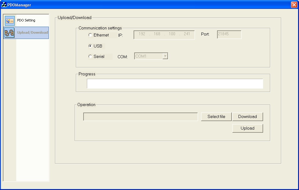 After the change, transfer the new ESDS configuration to your Kinco HMI via download.
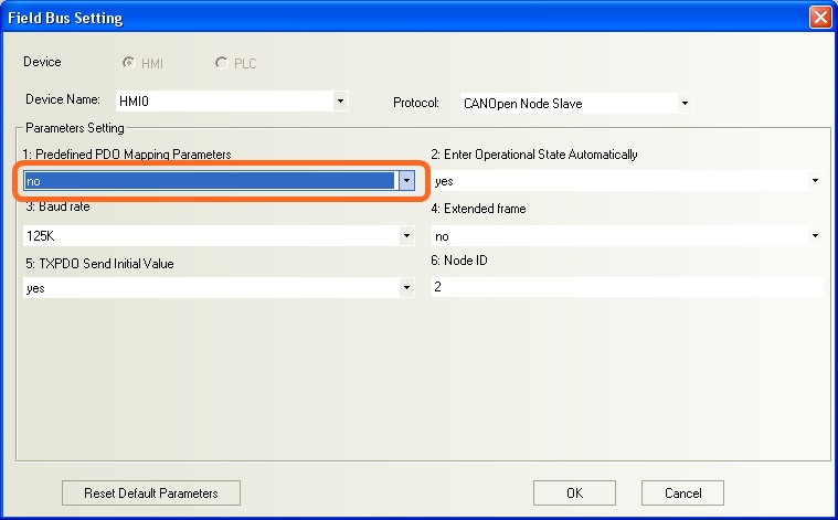 Important: In order for the adapted mapping to be applied, you must set the value for "Predefined PDO Mapping Parameters" to "No" in the fieldbus settings in the configuration of your HMI.
-


