


Kinco AK840M and RP20 – Support, Wiring Diagram & Commissioning
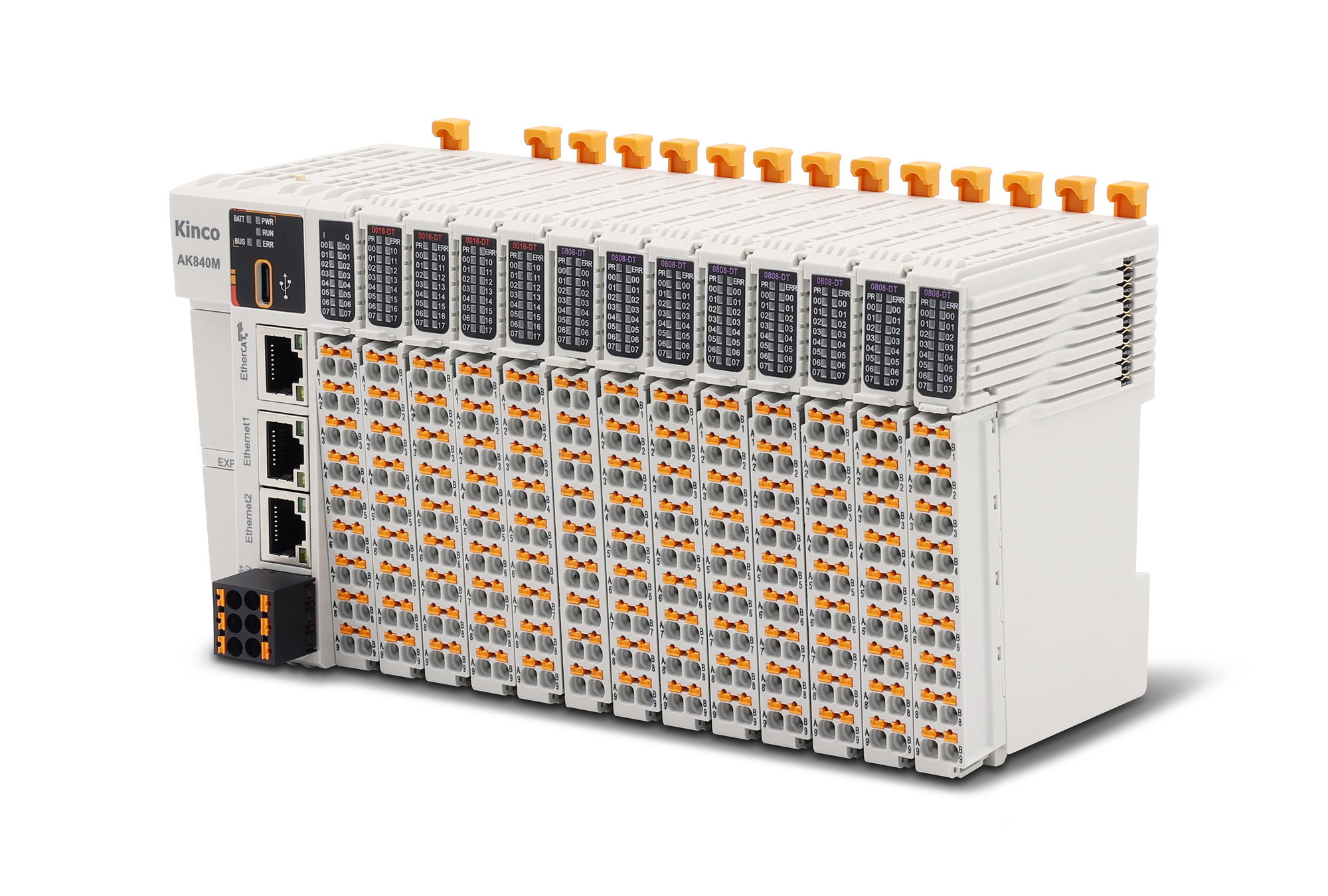
Everything for your Kinco AK840M and RP20 after purchase – for the AK840M CODESYS PLC with the BD20 boards and the RP20C-ECT EtherCAT bus coupler, both with all RP20 I/O modules:
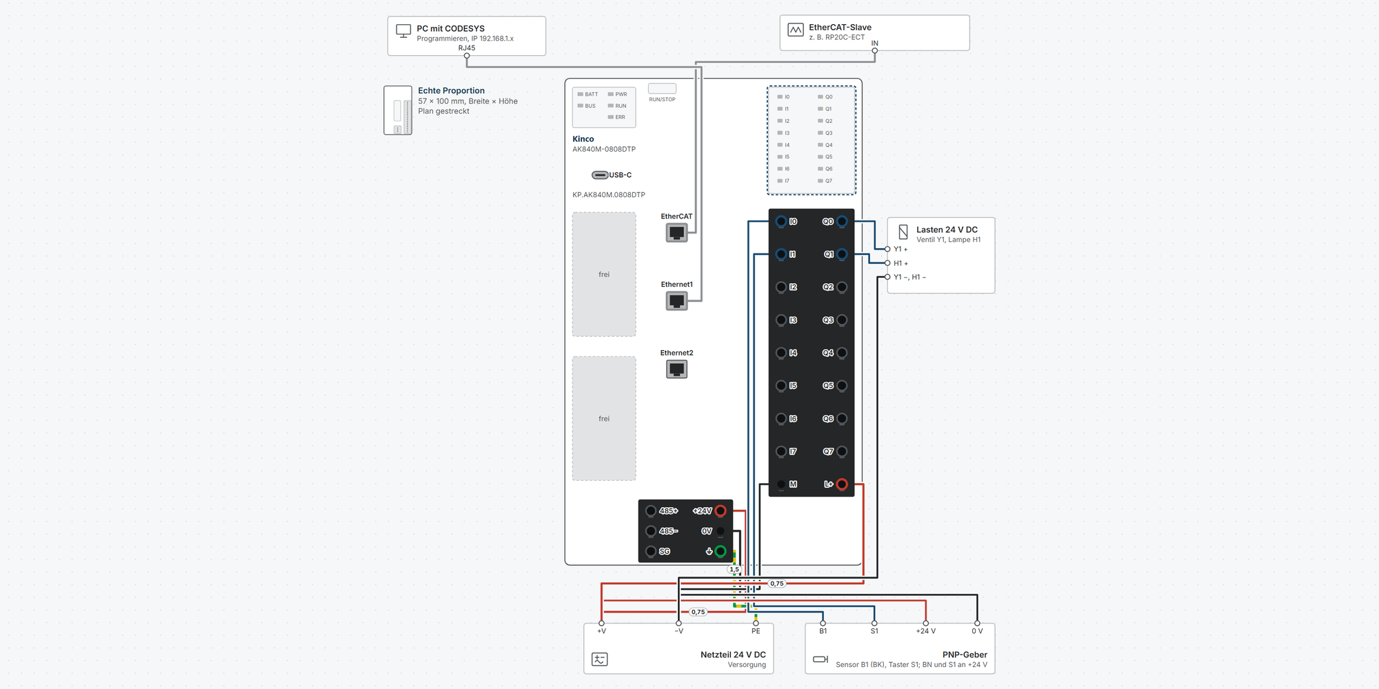
Interactive wiring diagram: power supply with current budget on the K-bus, EtherCAT, Ethernet, Modbus RTU, PNP and NPN sensors, encoder, loads, relays, 0–10 V and 4–20 mA transmitters, analog outputs, Pt100, thermocouples and the BD20 boards (CANopen, RS-485, RS-232), with cable cross-sections and parameters
First steps: commissioning in 14 steps, from the DIN rail to the first signal in CODESYS
Dimensions & mounting: width of your station, DIN rail and connectors
Downloads: manuals of the AK840M and RP20 modules, device package for CODESYS, ESI file of the coupler, dimension drawing and 3D models
Free support from spstiger if you get stuck
Interactive wiring diagram
Tap a terminal or wire in the drawing to see details.
Terminal overview AK840M
| Terminal | Group | mm² | Function |
|---|---|---|---|
| USB-C | USB-C | – | USB OTG for firmware updates and programs from a USB stick (FAT32), e.g. with a USB-A to USB-C adapter. Programming is not done via USB but via Ethernet1 or Ethernet2 (manual chap. 3.3, 8.3). |
| EtherCAT | EtherCAT and Ethernet | – | EtherCAT master for up to 32 axes, sync cycle from 1 ms (8 axes at 1 ms). Cable to IN of the first slave, e.g. RP20C-ECT or servo drive (manual chap. 3.3). |
| Ethernet1 | EtherCAT and Ethernet | – | Programming with CODESYS, Modbus TCP master or slave (up to 31 slaves per interface). Factory default IP address 192.168.1.100 (manual chap. 4). |
| Ethernet2 | EtherCAT and Ethernet | – | Second, separate network: also programming and Modbus TCP. Factory default IP address 192.168.2.100. Ethernet1 and Ethernet2 must not be in the same subnet, otherwise the device only recognises one of the two interfaces (manual chap. 4). |
| 485+ | Supply and RS-485 (6-pin) | 0.2–1.5* | RS-485 plus. Modbus RTU master or slave, up to 31 slaves (manual chap. 3.3, 5.1). |
| 485− | Supply and RS-485 (6-pin) | 0.2–1.5* | RS-485 minus. |
| SG | Supply and RS-485 (6-pin) | 0.2–1.5* | Reference (signal ground) of the RS-485. |
| +24V | Supply and RS-485 (6-pin) | 0.2–1.5* | Supply 24 V DC (19.2–28.8 V), 6 W without, up to 20 W with expansions; protected against reverse polarity and overcurrent (manual chap. 3.2). |
| 0V | Supply and RS-485 (6-pin) | 0.2–1.5* | Reference of the supply. |
| ⏚ | Supply and RS-485 (6-pin) | 0.2–1.5* | Earth (“Power Supply Ground” in the manual), to the earth bar of the control cabinet. |
| I0 | Inputs and outputs (2 × 9) | 0.2–1.5* | Digital input 24 V DC, PNP or NPN via M; 1 signal from 11 V (2 mA), 0 signal up to 5 V. HSC0 track A or pulse, up to 200 kHz (manual chap. 8.8). |
| I1 | Inputs and outputs (2 × 9) | 0.2–1.5* | Digital input 24 V DC, PNP or NPN via M; 1 signal from 11 V (2 mA), 0 signal up to 5 V. HSC0 track B or direction, up to 200 kHz (manual chap. 8.8). |
| I2 | Inputs and outputs (2 × 9) | 0.2–1.5* | Digital input 24 V DC, PNP or NPN via M; 1 signal from 11 V (2 mA), 0 signal up to 5 V. HSC1 track A or pulse, up to 200 kHz (manual chap. 8.8). |
| I3 | Inputs and outputs (2 × 9) | 0.2–1.5* | Digital input 24 V DC, PNP or NPN via M; 1 signal from 11 V (2 mA), 0 signal up to 5 V. HSC1 track B or direction, up to 200 kHz (manual chap. 8.8). |
| I4 | Inputs and outputs (2 × 9) | 0.2–1.5* | Digital input 24 V DC, PNP or NPN via M; 1 signal from 11 V (2 mA), 0 signal up to 5 V. Latch input HSC0, up to 200 kHz (manual chap. 8.8). |
| I5 | Inputs and outputs (2 × 9) | 0.2–1.5* | Digital input 24 V DC, PNP or NPN via M; 1 signal from 11 V (2 mA), 0 signal up to 5 V. |
| I6 | Inputs and outputs (2 × 9) | 0.2–1.5* | Digital input 24 V DC, PNP or NPN via M; 1 signal from 11 V (2 mA), 0 signal up to 5 V. Latch input HSC1, up to 200 kHz (manual chap. 8.8). |
| I7 | Inputs and outputs (2 × 9) | 0.2–1.5* | Digital input 24 V DC, PNP or NPN via M; 1 signal from 11 V (2 mA), 0 signal up to 5 V. |
| M | Inputs and outputs (2 × 9) | 0.2–1.5* | Common reference of the inputs I0–I7. PNP sensors: M to 0 V. NPN sensors: M to +24 V (manual fig. 5.2-2). |
| Q0 | Inputs and outputs (2 × 9) | 0.2–1.5* | Transistor output PNP, switches +24 V from L+ to the load, max. 300 mA; resistive 7.2 W, inductive 3.6 W per channel, short-circuit proof (manual chap. 3.4). |
| Q1 | Inputs and outputs (2 × 9) | 0.2–1.5* | Transistor output PNP, switches +24 V from L+ to the load, max. 300 mA; resistive 7.2 W, inductive 3.6 W per channel, short-circuit proof (manual chap. 3.4). |
| Q2 | Inputs and outputs (2 × 9) | 0.2–1.5* | Transistor output PNP, switches +24 V from L+ to the load, max. 300 mA; resistive 7.2 W, inductive 3.6 W per channel, short-circuit proof (manual chap. 3.4). |
| Q3 | Inputs and outputs (2 × 9) | 0.2–1.5* | Transistor output PNP, switches +24 V from L+ to the load, max. 300 mA; resistive 7.2 W, inductive 3.6 W per channel, short-circuit proof (manual chap. 3.4). |
| Q4 | Inputs and outputs (2 × 9) | 0.2–1.5* | Transistor output PNP, switches +24 V from L+ to the load, max. 300 mA; resistive 7.2 W, inductive 3.6 W per channel, short-circuit proof (manual chap. 3.4). |
| Q5 | Inputs and outputs (2 × 9) | 0.2–1.5* | Transistor output PNP, switches +24 V from L+ to the load, max. 300 mA; resistive 7.2 W, inductive 3.6 W per channel, short-circuit proof (manual chap. 3.4). |
| Q6 | Inputs and outputs (2 × 9) | 0.2–1.5* | Transistor output PNP, switches +24 V from L+ to the load, max. 300 mA; resistive 7.2 W, inductive 3.6 W per channel, short-circuit proof (manual chap. 3.4). |
| Q7 | Inputs and outputs (2 × 9) | 0.2–1.5* | Transistor output PNP, switches +24 V from L+ to the load, max. 300 mA; resistive 7.2 W, inductive 3.6 W per channel, short-circuit proof (manual chap. 3.4). |
| L+ | Inputs and outputs (2 × 9) | 0.2–1.5* | Supply of the PNP outputs with +24 V. Loads go from Qx to 0 V (manual fig. 5.2-2). |
* Clamping range not stated in the manual, derived.
First steps with AK840M and RP20
The AK840M is a CODESYS PLC with EtherCAT master, the RP20C-ECT an EtherCAT bus coupler. Both take up to 16 RP20 I/O modules on the right – the same modules, the same wiring. Choose your head and you will only see the steps that apply to you.
Mount, wire and unplug connectors only with the power off (manuals chap. 1).
Degree of protection IP20: AK840M, coupler and modules belong in a control cabinet.
Route control and bus cables at least 100 mm away from power cables, not in the same bundle.
Provide external fuses for outputs and loads; set up emergency stop and interlocks outside the PLC.
What sits on the left of your station?
1Plan the station: modules, order, K-bus currentRequired
The head sits on the left – AK840M or RP20C-ECT – with up to 16 RP20 modules in any order to its right.
Head and modules communicate via the K-bus. The AK840M supplies 5 V with about 1500 mA for it, the coupler 2 A. If that is not enough, insert an RP20-PW: it supplies the modules to its right with 2 A again.
In the wiring diagram you put your station together; the current budget per section is shown below the module chain.
K-bus current of the modules (5 V)
Module Current RP20-1600DT, -0016DTP, -0808DTP, -0008DR 135 mA RP20-0400IV, -0202IV 150 mA RP20-0004IV 140 mA RP20-0400RD, -0400TC 160 mA RP20-PW supplies 2000 mA Calculation according to the manual: simply add the currents (AK840 chap. 10.3). Example: 10 digital modules need 1350 mA and only just fit on the AK840M.
Do not place thermocouple modules directly next to the coupler, RP20-PW or output modules: their heat distorts the internal cold junction (analog manual chap. 8.3.4).
Source: AK840 chap. 3.3, 10.3; coupler manual chap. 5, 11.1
2Mount on the DIN railRequired
DIN rail 35 mm, 1 mm thick (7.5 or 15 mm high). Thinner rails do not hold securely, thicker ones prevent the latch from closing.
First the head: pull up the latch at the top, place it vertically on the rail, release the latch.
On the coupler, first remove the cover plate on the right-hand side. Then thread each module into the previous one with its guides at the top and bottom, push it back to the rail and let it latch.
Finally fit an end stop matching the rail on the left and on the right – it is not included in the scope of delivery.
Removal: loosen the end stops, lift the latch with a flat-blade screwdriver, pull the module off towards the front (manuals chap. 7.2 and 8.2).
Source: AK840 chap. 7.2; DIO manual chap. 8.2; coupler manual chap. 8.2
3Connect the supplyRequired
Head: 24 V DC to the supply connector – on the AK840M to B1 (+24V), B2 (0V), B3 (earth) of the 6-pin connector, on the coupler to column A. Column B of the coupler is connected through and is used for looping through.
Modules: output modules (L+/L−), the relay module (coils 24V/0V) and the modules with analog outputs (24V/0V) need 24 V at their own terminals in row 9. Input and temperature modules need none.
RP20-PW: 24 V to 24V, 0V and earth; the remaining terminals distribute the 24 V further.
Show wiring “24 V supply”Show wiring “Field supply L+/L−”Show wiring “24 V supply”Show wiring “Supply RP20-PW”
Source: AK840 chap. 5.1, 5.5; DIO manual chap. 7; analog manual chap. 7; coupler manual chap. 6.1
4Wire inputs and outputsRequired
All connectors are pluggable spring terminals: push in the wire, press the orange pusher to release it. You can pull off the whole connector for wiring; spares are available as the RP20 terminal block.
Digital inputs: AK840M and RP20-1600DT take PNP or NPN sensors, one logic per group via M or 1M/2M. The RP20-0808DTP takes PNP sensors only.
Digital outputs switch +24 V (PNP). Analog inputs: voltage at X+ and X−, current at RX and X−. Factory default is 4–20 mA.
Pt100 on the RP20-0400RD with 3 wires; with 2 wires fit a jumper between the 2nd and 3rd terminal.
The Kinco manuals do not state a clamping range; 0.5 mm² for signals and 0.75 mm² for the supply fit into common push-in terminals of this size (derived).
Show wiring “PNP sensors on I0, I1”Show wiring “Loads on Q0, Q1”Show wiring “PNP sensors”Show wiring “Transmitter 4–20 mA on channel B”Show wiring “Pt100 3-wire on channel A”
Source: AK840 chap. 5.2; DIO manual chap. 7; analog manual chap. 7
5Switch on and check the LEDsRequired
After switching on, PWR lights on the head. On each module PR shows the state: slow flashing means “not yet set up by the master” – that is correct before the first download.
LED Meaning PWR on Supply OK (AK840M and coupler) BUS on (AK840M) Modules detected · flashing: fault at a module SF on (coupler) Fault on the K-bus ERR on Fault on the EtherCAT bus PR slow flashing Module waiting for configuration PR on Module running Err on (module) internal fault of the module Source: AK840 chap. 4; DIO manual chap. 5; coupler manual chap. 4
6AK840M: install CODESYS and the device packageARequired
Programming is done with CODESYS V3.5 (the manual shows SP19). The device package “Kinco XMLs for AK84x … .package” from the download center contains the AK840M, BD20 boards and RP20 modules.
Installing the package
Open CODESYS, Tools → CODESYS Installer.
In the installer choose Install File and open the .package file. Close CODESYS first, otherwise the installation aborts.
Confirm the prompt with “I want to continue despite the missing signature” and click Continue.
Wait until the installation has finished, close the installer and restart CODESYS.
Which CODESYS version? The runtime in the AK840M is version 3.5.20.20. We work with CODESYS V3.5 SP22 and the device package 1.0.2.16; we have no explicit approval from Kinco for SP22.
Every CODESYS version and every patch is a separate installation. You have to install the device package again there (as observed on our systems).
If you open a project in a newer CODESYS version, the Project Environment dialog asks about the compiler version. Update it for new projects. If the machine is already running, plan the change: afterwards a full download with a stop of the controller is usually required.
A project saved in a newer CODESYS version can no longer be opened in an older one.
The AK840M has an OPC UA server. WebVisu is only available on the AK842M, EtherNet/IP only on the AK841M (manual chap. 3.3, 8.13 and 8.14).
Source: AK840 chap. 3.3, 8.1, 8.2, 8.13, 8.14; device description in package 1.0.2.16; our own installation
7AK840M: connect and load the first programARequired
Connect the PC to Ethernet1 with a patch cable and set a fixed address in the network 192.168.1.x on the PC, e.g. 192.168.1.10 / 255.255.255.0. By default the AK840M has 192.168.1.100 on Ethernet1 and 192.168.2.100 on Ethernet2.
In CODESYS
Create a new standard project and select the AK840M as the device.
Double-click Device, scan the network under Communication Settings and select the AK840M.
Set the RUN/STOP switch on top of the device to RUN.
Click Login in the toolbar, confirm the download prompt with Yes, then Start.
Without a network you can also use a USB stick or FTP (manual chap. 8.4).
Modbus TCP slave on ETH1 (port 502, station 1) is already created in a new project (chap. 8.6.1).
Source: AK840 chap. 4, 8.4.1, 8.6.1
8AK840M: add RP20 modules and BD20 boardsARequired
In CODESYS you add the RP20 modules under localbus – by hand and exactly in the order on the DIN rail, otherwise the K-bus reports a fault.
Each module gets its addresses automatically. You find them in the module under Module I/O Mapping: assign variables there or use the addresses (byte/bit) directly in the program.
BD20 boards: right-click EXP_0 or EXP_1 → Add Device → select the board. Then create the interface under Device, e.g. CANbus with CANopen Manager (BD20-CAN) or Modbus Master 485 (BD20-COM).
Analog and temperature modules: you set the measuring range, filter and behaviour on loss of connection in the startup parameters of the module (analog manual chap. 8).
Show wiring “PNP sensors”Show wiring “BD20-CAN: CANopen”Show wiring “BD20-COM: RS-485”
Source: DIO manual chap. 9.2.2; analog manual chap. 11.2.2; AK840 chap. 8.10, 8.11
9AK840M: change the IP addressAOptional
In CODESYS
Log in, double-click Device → tab PLC Parameters.
Enter the new address for the desired interface in the column for the prepared value.
Click Write Parameters at the top right.
Restart the device – only then does the new address apply.
Do not put Ethernet1 and Ethernet2 in the same subnet, otherwise the device only recognises one of the two interfaces (manual chap. 4).
Address no longer known? The IP address can be reset with an update file. You can get the file from our support (manual chap. 8.5).
Source: AK840 chap. 4, 8.5
10AK840M: update the firmware⚠ CautionAOptional
Program is lost
Firmware files with the suffix “delapp” delete the user program in the AK840M.
Via USB stick
Copy the firmware file to the root directory of a USB stick formatted with FAT32.
Plug the stick into the USB-C socket (stick with USB-C or adapter) and switch the AK840M off and on.
RUN flashes green: update in progress, do not switch off. RUN steady green: finished.
Known faults fixed by a firmware patch
Behaviour Remedy Analog modules on the AK840M no longer deliver values after a power failure Patch 251021A The high-speed counters (HSIO) do not start if no RP20 module is fitted to the AK840M Patch 260304A Alternatively via CODESYS (file under Device → Files into the root directory) or via FTP (manual chap. 8.3).
Check: after a successful update the file “Upgrade_OK” is in the root directory of the USB stick or of the runtime; the version is shown under Device → PLC Parameters → Firmware Version (manual chap. 8.3).
The patches are not in the download center. Tell our support which firmware version your AK840M shows – we will send you the matching patch.
Source: AK840 chap. 8.3; change log of the Kinco firmware patches 251021A and 260304A
11AK840M: finding faultsAOptional
The LEDs show where the fault is. The cause is in the Log of the AK840M.
Reading the log
Log in to the device in CODESYS.
Double-click Device, tab Log.
Click Refresh: the list shows the latest messages of the device.
Observation Check CODESYS does not find the AK840M Are the PC and the socket used in the same network? By default Ethernet1 has 192.168.1.100 and Ethernet2 192.168.2.100 – two separate networks. If both sockets are in the same subnet, the device only recognises one of them. Programming is not done via the EtherCAT socket and not via USB. RUN off Program stopped: set the RUN/STOP switch to RUN, click Start in CODESYS. BUS off although modules are fitted Modules not detected: are all modules latched together? Is the K-bus current sufficient (current budget in the wiring diagram)? BUS flashing Fault at a module: is the order under localbus the same as on the DIN rail? Err LED lit on a module? ERR on Fault on the EtherCAT bus: cable from the EtherCAT socket to IN of the first slave, order and ESI files of the slaves in the project. BAT on Backup battery low or not inserted. Analog values missing after a power failure, counters do not run without a fitted module Check the firmware version, see the step “Update the firmware”. The manual lists the general fault codes of the runtime in chap. 9.2, the messages of the Modbus RTU master in chap. 8.7.3 and those of the high-speed counters in chap. 8.8.2.
The checks for the LEDs follow from their meaning (manual chap. 4); the manual itself does not give remedies for them.
Source: AK840 chap. 4, 9.1, 9.2
12Coupler: install the ESI fileERequired
The device description RP20_ECT_….xml from the download center contains the coupler and all RP20 modules – there is no separate file per module.
In CODESYS
Tools → Device Repository.
Choose Install…, open the XML file and wait until the installation has finished.
Other EtherCAT masters read the same ESI file; the steps have different names there.
Source: Coupler manual chap. 9.1, 9.2
13Coupler: scan the station and assign variablesERequired
Patch cable from the master to IN of the coupler, further slaves to OUT.
In CODESYS
Under the EtherCAT master choose Scan for Devices and then Copy All Devices to Project – the coupler is added to the project together with its modules in the correct order.
Without a connected station: right-click the master → add RP20C_ECT, then add the modules to the coupler in the order on the DIN rail.
For each module assign variables under Module I/O Mapping or use the addresses directly.
Download and start: RUN on the coupler lights steadily (state OP).
Digital modules transfer their channels byte by byte; you set the startup parameters (filter, measuring range, behaviour on loss of connection) per module.
Show wiring “EtherCAT”Show wiring “Further slave on OUT”
Source: Coupler manual chap. 9.3, 9.4
14Coupler: finding faultsEOptional
SF indicates a fault on the K-bus, ERR one on EtherCAT. The cause is shown on the CoE Online tab of the coupler.
Object Content 0x3012:01 K-bus fault code, e.g. 0x08 = K-bus interrupted, 0x20 = modules do not match the configuration 0x3012:02 ID of the module at the interruption 0x3010:01 EtherCAT fault code, e.g. 0x04 = watchdog, 0x08 = synchronisation 0xA000 + 0x10 × (n − 1), subindex 4 Fault code of the module at position n: 0x01 master, 0x02 module, 0x03 wrong module ID For the table of K-bus codes the manual names subindex 1 in one place and subindex 4 in another; subindex 1 is used here according to the object description.
Source: Coupler manual chap. 10; DIO manual chap. 10
Revision 1.2 · 09.11.2026 · Source: AK84x User Manual V008 (10/2026), RP20 DIO Module User Manual V001 (05/2025), RP20 Analog Module User Manual V001 (04/2025), RP20 EtherCAT Coupler User Manual V002 (07/2025); menu names in CODESYS as in the manual (English user interface). The manufacturer manual and applicable standards take precedence; installation and commissioning by a qualified electrician only.
Dimensions and mounting
Head and modules sit vertically on a 35 mm DIN rail: the AK840M or the coupler on the left, the RP20 modules to the right, the cover at the far right. The drawing shows your station from the wiring diagram, projected from the Kinco 3D models.
Connectors and wires
AK840M supply and RS-485
- Type
- 6-pin, 2 × 3, pluggable spring terminal with locking
- Cross-section
- not specified
AK840M inputs and outputs
- Type
- 18-pin, 2 × 9, pluggable spring terminal
- Cross-section
- not specified
RP20C-ECT supply
- Type
- 2 × 3, columns A and B connected
- Cross-section
- not specified
RP20 modules
- Type
- 18-pin, 2 × 9, pluggable spring terminal
- Cross-section
- not specified
EtherCAT, Ethernet
- Type
- RJ45, Cat5e or better, max. 100 m
Spare connectors are available as the RP20 terminal block.
The Kinco manuals do not state a clamping range; in the wiring diagram 0.2–1.5 mm² is stored as an assumption and marked as such.
Mounting step by step
1Choose the installation site
Degree of protection IP20: the station belongs in a control cabinet, operation at −20 to 55 °C.
Place the station vertically on a horizontal DIN rail (35 mm wide, 1 mm thick, 7.5 or 15 mm high). The rail lies 5 mm below the centre of the device.
The manuals do not state minimum clearances. Leave room at the top and bottom for the latches and the cables.
2Mounting the station
Mount only with the power off.
Place the head on the DIN rail: pull up the latch at the top, put the device on vertically, release the latch.
Remove the cover plate on the right of the coupler, or the side cover on the AK840M.
Thread each module into the previous one with its guides at the top and bottom, push it back and let it latch.
Put the cover on the last module and screw an end stop matching the rail tight on the left and on the right (not included).
3Replacing a module
Switch off the power, loosen the end stops.
Lift the latch of the module with a flat-blade screwdriver.
Pull the module off towards the front; the modules behind it stay in place.
Thread in the new module, let it latch, screw the end stops tight again.
4Connecting the wires
All connectors are pluggable spring terminals: push in the wire, press the orange pusher to release it. To unplug, pull the connector forwards by its grip.
At the front of the module there are fixing points where you secure the cables with cable ties.
The manuals do not state cross-section and stripping length; usual values for this terminal size are 0.2–1.5 mm² (derived).
Show wiring “24 V supply”Show wiring “PNP sensors on I0, I1”
Revision 1.2 · 09.11.2026 · Source: AK84x User Manual V008 chap. 3.3, 6, 7; RP20 DIO Module User Manual V001 chap. 8; RP20 EtherCAT Coupler User Manual V002 chap. 7, 8; Kinco 3D models AK840M, RP20C-ECT, RP20 IO modules, RP20-0008DR. The manufacturer manual and applicable standards take precedence; installation by a qualified electrician only.
Stuck?
Our support helps you free of charge. Tell us what you are planning and which model you use – via the contact form, by email or in the community forum.
Contact formEmail support@spstiger.deAsk in the community forum
More ways to contact us: Support contacts
We have compiled and checked this page carefully from the manufacturer’s documentation. Even so, an error may have slipped in. The manufacturer’s manual and the applicable standards always take precedence. Spotted something? Let us know – we’ll be glad to fix it.
Downloads
You will find the manual of the RP20 digital modules, the coupler manual and the RP20 catalogue on the RP20 product pages under “Downloads”:
Here for the whole series: manuals of the AK840M and RP20 modules, device package for CODESYS, ESI file of the coupler, dimension drawing and 3D models:
Kinco AK840M, RP20 coupler and RP20 modules