


Kinco KC200 – Support, Wiring Diagram & Commissioning
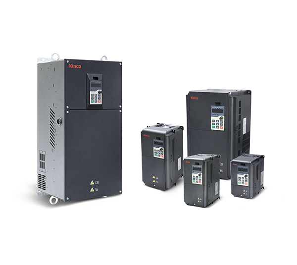
Everything for your Kinco KC200 after purchase – for all ten models from 1.5 to 45 kW, three-phase 400 V:
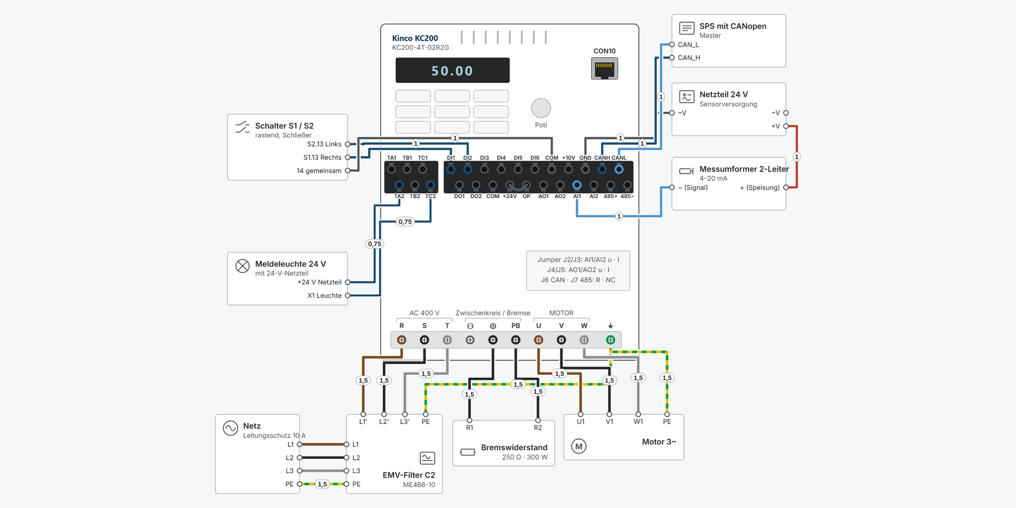
Interactive wiring diagram: mains and motor, start/stop, setpoint, analog sensors, Modbus RTU, CANopen, relay and braking resistor, with cable cross-sections and parameters
First steps: commissioning in nine steps, from the motor data to the first run
Operation: keypad simulator to try out, with exercises
Downloads: user manual, selection manual, CE documents, CANopen EDS and 2D and 3D drawings
Free support from spstiger if you get stuck
Keypad: keys, display and LEDs
MENU opens the menu for setting parameters – the most important key for programming. Try out the keypad here: set parameters, start and stop the motor, reset faults. The exercises guide you step by step through the most important procedures. Rest the mouse pointer on a key for a moment to see what it does right now.
Interactive wiring diagram
Tap a terminal or wire in the drawing to see details.
Terminal overview KC200
| Terminal | Group | mm² | Function |
|---|---|---|---|
| TA1 | RELAIS | – | TA1–TB1 normally closed, TA1–TC1 normally open. AC 250 V / 3 A, DC 30 V / 1 A. Function F10.02 (factory default 8). |
| TB1 | RELAIS | – | TA1–TB1 is closed in the idle state. |
| TC1 | RELAIS | – | TA1–TC1 closes when the relay function is active. |
| TA2 | RELAIS | – | TA2–TB2 normally closed, TA2–TC2 normally open. Same rating as relay 1. Function F10.03. |
| TB2 | RELAIS | – | TA2–TB2 is closed in the idle state. |
| TC2 | RELAIS | – | TA2–TC2 closes when the relay function is active. |
| DI1 | STEUER | – | NPN and PNP, 9–30 V, 4.7 kΩ, max. 200 Hz. Factory default: forward (F08.00 = 1). |
| DI2 | STEUER | – | NPN and PNP, 9–30 V, 4.7 kΩ, max. 200 Hz. Factory default: reverse (F08.01 = 2). |
| DI3 | STEUER | – | NPN and PNP, 9–30 V, 4.7 kΩ, max. 200 Hz. Function via F08.02. |
| DI4 | STEUER | – | NPN and PNP, 9–30 V, 4.7 kΩ, max. 200 Hz. Function via F08.03. |
| DI5 | STEUER | – | NPN and PNP, 9–30 V, 4.7 kΩ, max. 200 Hz. Function via F08.04. |
| DI6 | STEUER | – | NPN and PNP, 9–30 V, 2.2 kΩ, as pulse input up to 100 kHz. Function via F08.05. |
| COM | STEUER | – | Reference of the internal 24 V supply, internally connected to the second COM. Galvanically isolated from GND. |
| +10V | STEUER | – | Output +10 V, max. 10 mA – e.g. for a setpoint potentiometer (at least 1 kΩ). |
| GND | STEUER | – | Reference for AI1, AI2, AO1, AO2 and +10V. Galvanically isolated from COM. |
| CANH | STEUER | – | CAN High. Built-in termination resistor, connect with jumper J6 = R at the bus end. |
| CANL | STEUER | – | CAN Low. Route twisted and shielded. |
| DO1 | STEUER | – | Open collector to COM, max. 30 V / 50 mA. Factory default F10.00 = 2. |
| DO2 | STEUER | – | Open collector to COM, as pulse output up to 100 kHz (F11.02). |
| COM | STEUER | – | Second COM terminal, internally connected to COM of the upper row. Never short-circuit to +24V. |
| +24V | STEUER | – | 24 V DC, max. 200 mA for digital inputs and sensors. Linked to OP at the factory. |
| OP | STEUER | – | Linked to +24V at the factory. For PNP control from the internal 24 V or with an external supply, the jumper must be moved. |
| AO1 | STEUER | – | 0–10 V or 0/4–20 mA, selected with jumper J4, factory default voltage. Function F11.00. |
| AO2 | STEUER | – | 0–10 V or 0/4–20 mA, selected with jumper J5. Function F11.01. |
| AI1 | STEUER | – | 0–10 V or 0–20 mA, 12 bit, single-ended to GND. Selected with jumper J2 (u = voltage, I = current). Input 20 kΩ (U) / 500 Ω (I). |
| AI2 | STEUER | – | Like AI1, selected with jumper J3. |
| 485+ | STEUER | – | Plus of the differential signal. Built-in termination resistor, connect with jumper J7 = R at the bus end. Do not confuse with the adjacent AI2. |
| 485− | STEUER | – | Minus of the differential signal. Route twisted and shielded. |
| R | LEISTUNG | – | Three-phase 380–480 V. Line protection 1.5–2 × input current (manual Tab. 3-1). |
| S | LEISTUNG | – | Three-phase 380–480 V. |
| T | LEISTUNG | – | Three-phase 380–480 V. |
| ⊖ | LEISTUNG | – | For a common DC bus. Not for the braking resistor. |
| ⊕ | LEISTUNG | – | Braking resistor between ⊕ and PB. Brake chopper built-in up to 45 kW. |
| PB | LEISTUNG | – | Second connection of the braking resistor. Never connect to ⊖. |
| U | LEISTUNG | – | Motor output. Never apply mains voltage to U/V/W. |
| V | LEISTUNG | – | Motor output. Never apply mains voltage to U/V/W. |
| W | LEISTUNG | – | Motor output. Never apply mains voltage to U/V/W. |
| ⏚ | LEISTUNG | – | Connect PE first. Up to 22 kW separate earthing screw, from 30 kW part of the terminal strip. Earth the motor separately as well. |
| CON10 | – | – | Connection for the external keypad (RJ45 pinout 1: 485+, 2: 485−, 5: GND, 7: +5V) and the PG card. |
* Clamping range not stated in the manual, derived.
First steps with the Kinco KC200
Nine steps from unboxing to the first motor run: connect, enter motor data, set start/stop and setpoint, adjust ramps. You only need Modbus, CANopen, digital inputs and the braking resistor if your application uses them.
Disconnect all supplies and wait at least 10 minutes until the charge indicator has gone out. Only then touch the terminals.
The KC200 has no STO. Implement safe motor shutdown on site with a contactor or safety circuit.
Always connect the protective earth (PE) first.
1Connect mains and motorRequired
Mains goes to R, S and T, the motor to U, V and W, plus PE at the inverter and motor. Up to 22 kW, PE has its own earthing screw; from 30 kW, ⏚ is part of the terminal row.
The wiring diagram shows line protection and cross-sections for your model in the scenario “Mains and motor”.
Circuit breaker: 1.5 to 2 times the rated current of the inverter; a universal-current-sensitive residual current device type B is recommended (manual Tab. 3-1).
Never apply mains voltage to U, V, W. From 100 m of motor cable, an output reactor is recommended.
Source: kc200/10-klemmen, kc200/10b-installation
2Enter motor data and motor auto-tuningRequired
The values are on the motor's rating plate. All parameters in this step can only be changed at standstill.
Parameter Value Meaning F03.00 0 Motor type: 0 = asynchronous motor (factory default), 1 = synchronous motor F03.02 Rating plate Rated motor power in kW F03.03 Rating plate Rated motor voltage in V F03.04 Rating plate Rated motor current in A F03.05 Rating plate Rated motor frequency, usually 50.00 Hz in Europe F03.06 Rating plate Rated motor speed in min⁻¹ F01.02 0, 1 or 2 Control mode: 0 = V/f control (factory default), 1 = sensorless vector control (SVC), 2 = vector control with encoder (FVC, PG card required) Motor auto-tuning
Mechanically uncouple the motor from the load so that it can rotate freely.
F01.03 = 0 (start via the keypad).
Enter F03.02 to F03.06 from the rating plate.
Set F03.09 = 2 and confirm with ENTER; the display shows EST·00.
Press RUN. Auto-tuning takes about 2 minutes; RUN lights up and ALM flashes.
When the display disappears, auto-tuning is complete; F03.10 to F03.14 are calculated.
If the motor cannot be uncoupled from the load, F03.09 = 1 determines some of the parameters at standstill. For synchronous motors, the back EMF (F03.23) must then be entered manually.
Practise on the keypad: “Enter motor data and start motor auto-tuning”
Source: kc200/01-basis, manual chap. 5.6.2
3Set the start/stop sourceRequired
F01.03 defines where the run command comes from. You set the setpoint separately in step 4.
Parameter Value Meaning F01.03 0 Keypad: RUN and STOP on the device (factory default) F01.03 1 Terminals: DI1 forward, DI2 reverse (factory default F08.00 = 1, F08.01 = 2) F01.03 2 Communication: Modbus RTU or CANopen, see step 7 F08.10 0 Terminal control two-wire type 1 (factory default); 2 = three-wire type 1 OP is the common terminal of DI1–DI6 and is jumpered to +24V by default. If a PLC with PNP outputs or an external 24 V supply controls the inputs, the jumper must be moved. Never short-circuit +24V and COM.
Show wiring “Start/stop via switch”Show wiring “Start/stop from PLC (PNP)”
Practise on the keypad: “Start and stop the motor from the keypad”Practise on the keypad: “Switch start/stop to terminals”Practise on the keypad: “Change rotation direction with FWD/REV”
Source: kc200/01-basis, kc200/02-io, kc200/10-klemmen
4Set the setpointRequired
F01.04 defines where the frequency setpoint comes from – independent of the start/stop source.
Parameter Value Meaning F01.04 0 Digital on the keypad, value in F01.10 (factory default) F01.04 4 Potentiometer on the keypad F01.04 1 / 2 Analog input AI1 / AI2 (0–10 V or 0–20 mA, selected with jumper J2 / J3) F01.04 5 Communication (Modbus RTU or CANopen) F01.04 6 / 7 / 8 Pulse input DI6 / PID controller / multi-step setpoint F01.11 50.00 Hz Maximum frequency (factory default, up to 599.00 Hz); reference for ramps and Modbus setpoint F01.13 / F01.14 50.00 / 0.00 Hz Upper and lower frequency limit (factory default) For an external potentiometer or 0–10 V, set jumper J2 to u; for 4–20 mA set it to I and adjust the AI curve (AI1 uses curve 1 by default, F09.21–F09.24). The jumpers are only accessible with the cover removed.
Show wiring “Setpoint via potentiometer”Show wiring “Setpoint 4–20 mA from PLC”Show wiring “Sensor 2-wire 4–20 mA”Show wiring “Sensor 3-wire 0–10 V”
Practise on the keypad: “Set frequency setpoint F01.10 to 15.00 Hz”Practise on the keypad: “Set the setpoint with the potentiometer”
Source: kc200/01-basis, kc200/02-io, kc200/10-klemmen
5Set acceleration and deceleration timeRequired
By default, the times refer to the maximum frequency F01.11. The factory default depends on the power rating.
Parameter Value Meaning F01.23 10.0 / 20.0 s Acceleration time 1: up to 5.5 kW 10.0 s, 11–45 kW 20.0 s (factory default, 0.0–6000.0 s) F01.24 10.0 / 20.0 s Deceleration time 1: same as acceleration time (factory default) F01.20 0 Ramp shape: 0 = linear (factory default), 1 = S-curve F01.21 0 Ramp reference: 0 = maximum frequency (factory default) If the inverter reports E0001 (overcurrent) while accelerating, increase the acceleration time. For E0005 (overvoltage while decelerating), increase the deceleration time or connect a braking resistor (step 8).
Practise on the keypad: “Shorten acceleration time F01.23 to 5.0 s”
Source: kc200/01-basis
6Assign digital inputsOptional
The KC200 has six digital inputs DI1–DI6 (PNP and NPN, 9–30 V). DI6 is also a pulse input up to 100 kHz. You set the function in F08.00 (DI1) to F08.05 (DI6).
Value Function Value Function 1 Forward run (FWD) 7 Emergency stop 2 Reverse run (REV) 9 Switch command channel terminal ↔ communication 3 Three-wire control 12 Immediate DC braking 4 / 5 Jog forward / reverse 32 / 33 Select acceleration/deceleration time 1 / 2 6 Coast stop (free run) 8 Switch command channel local ↔ remote The complete function list (including fault reset, preset frequencies, pulse input) is in the manual, chap. 7, group F08.
Show wiring “Start/stop via switch”
Source: kc200/02-io
7Configure Modbus RTU or CANopenOptional
The KC200 has RS-485 (Modbus RTU, terminals 485+ and 485−) and CAN (CANopen, CANH and CANL). The termination resistors are built in: at the bus end, set J7 (485) or J6 (CAN) to R.
Parameter Value Meaning F14.01 5 Modbus baud rate 38400 (factory default); 3 = 9600, 4 = 19200, 7 = 115200 F14.02 0 Data format N,8,1 (factory default) F14.03 1 Modbus address (1–247) F14.20 5 CAN baud rate 500 kbit/s (factory default) F14.21 1 CANopen node address (1–127) F01.03 / F01.04 2 / 5 Both required so that run command and setpoint take effect via the bus Modbus control registers
Register Value Meaning 0x7000 (28672) 0x0001 / 0x0002 Forward / reverse 0x7000 (28672) 0x0005 / 0x0007 Ramp stop / coast stop 0x7000 (28672) 0x0008 Fault reset 0x7010 (28688) 0–10000 Setpoint 0.00–100.00 % of maximum frequency F01.11 0x6F00 (28416) read Current fault code Example for 0x7010 (calculated): with F01.11 = 50.00 Hz, 10000 (0x2710) gives 50 Hz and 5000 (0x1388) gives 25 Hz.
485+/485− are at the far right of the lower row, directly next to AI2 – do not mix them up when connecting.
The EDS file for CANopen is in the download area.
Show wiring “Modbus RTU to PLC”Show wiring “CANopen to PLC”
Practise on the keypad: “Set CANopen node address F14.21 to 5”
Source: kc200/03-modbus, kc200/05-canopen, kc200/10-klemmen
8Connect a braking resistorOptional
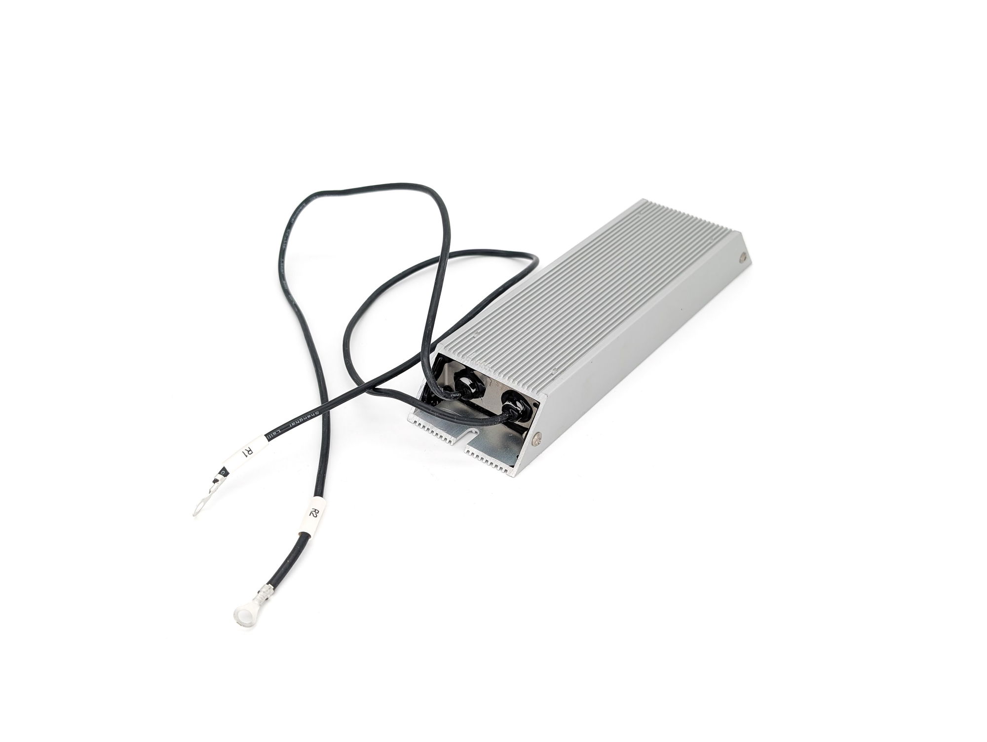
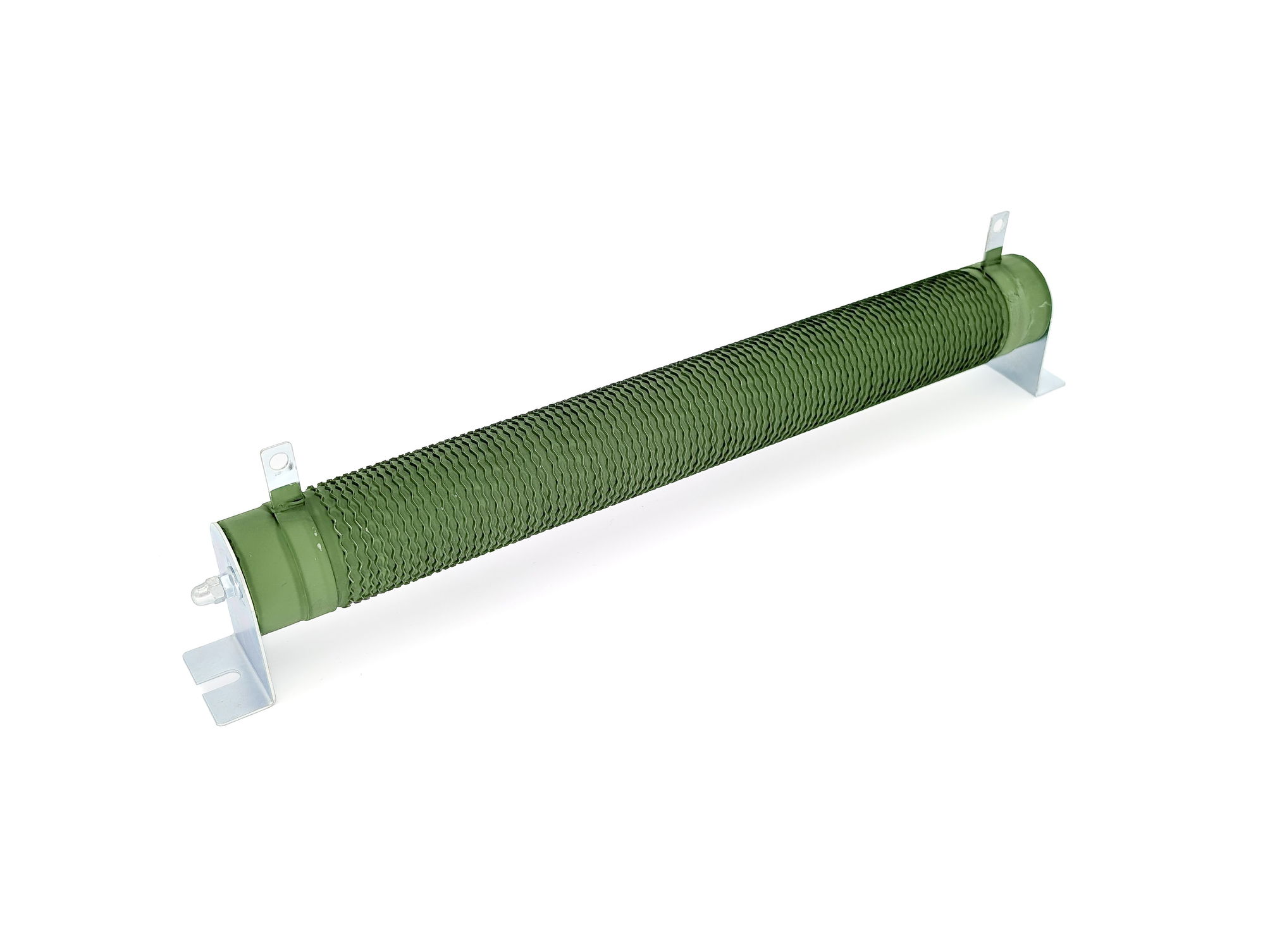
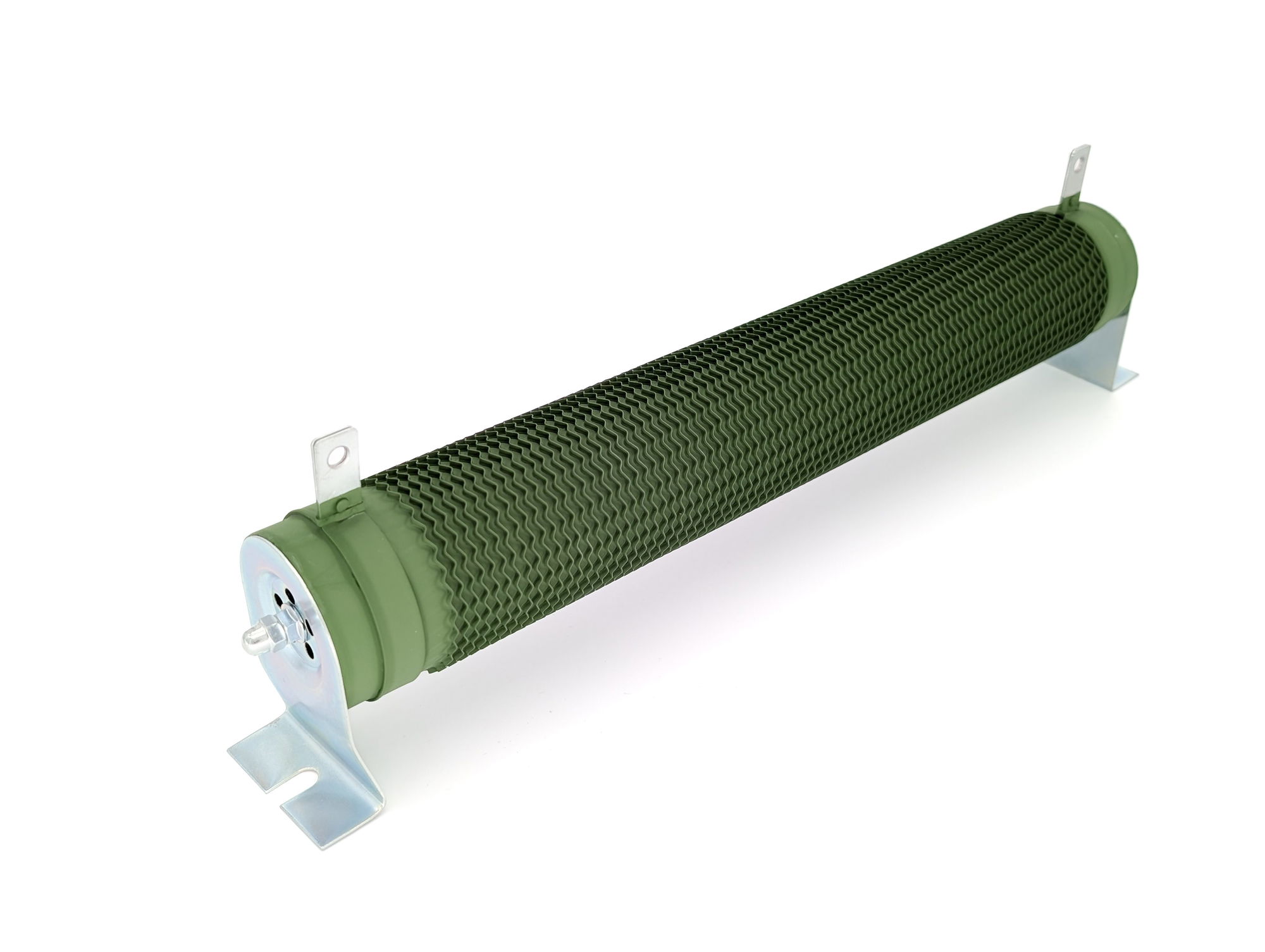
Up to 45 kW, the brake chopper is built in. For fast or frequent braking, connect an external braking resistor to ⊕ and PB. The wiring diagram gives the recommended resistor for your model.
Parameter Value Meaning F13.17 700.0 V Chopper switch-on threshold for 400 V devices (factory default) F13.18 100.0 % Duty cycle of the braking unit (factory default, can only be changed at standstill) Show wiring “Braking resistor”
Practise on the keypad: “Reset fault E0005”
Source: kc200/07-funktionen, kc200/10b-installation
9First runRequired
Common messages on the first run
Code Meaning Remedy E0001 Overcurrent while accelerating Increase acceleration time, check motor data and load E0005 Overvoltage while decelerating Increase deceleration time or connect a braking resistor E0013 Motor self-identification fault Check rating plate data and motor connection, repeat auto-tuning E0024 Motor overload Check load and rated motor current F03.04 E0029 Communication timeout Check bus connection and timeout (F14.05 or F14.22) E0010 Earth fault at the motor Check motor and motor cable Causes and remedies for each code are in the manual, chap. 6.
Practise on the keypad: “Start and stop the motor from the keypad”Practise on the keypad: “Read operating values and fault memory in the D group”
Source: kc200/01-basis
Revision 2.0 · 26.09.2026 · Source: Kinco KC200 User Manual (09/2026), prepared in spstiger vfd-konfig (kc200/01-basis, 02-io, 03-modbus, 05-canopen, 07-funktionen, 10-klemmen, 10b-installation). The manufacturer manual and applicable standards take precedence; installation and commissioning by a qualified electrician only.
Multi-speed operation
Select preset frequencies via digital inputs: step by step for KC100 and KC200. Multi-speed operation Kinco KC100 and KC200
Stuck?
Our support helps you free of charge. Tell us what you are planning and which model you use – via the contact form, by email or in the community forum.
Contact formEmail support@spstiger.deAsk in the community forum
More ways to contact us: Support contacts
Downloads
User manual, selection manual, CE documents, CANopen EDS and 2D and 3D drawings:
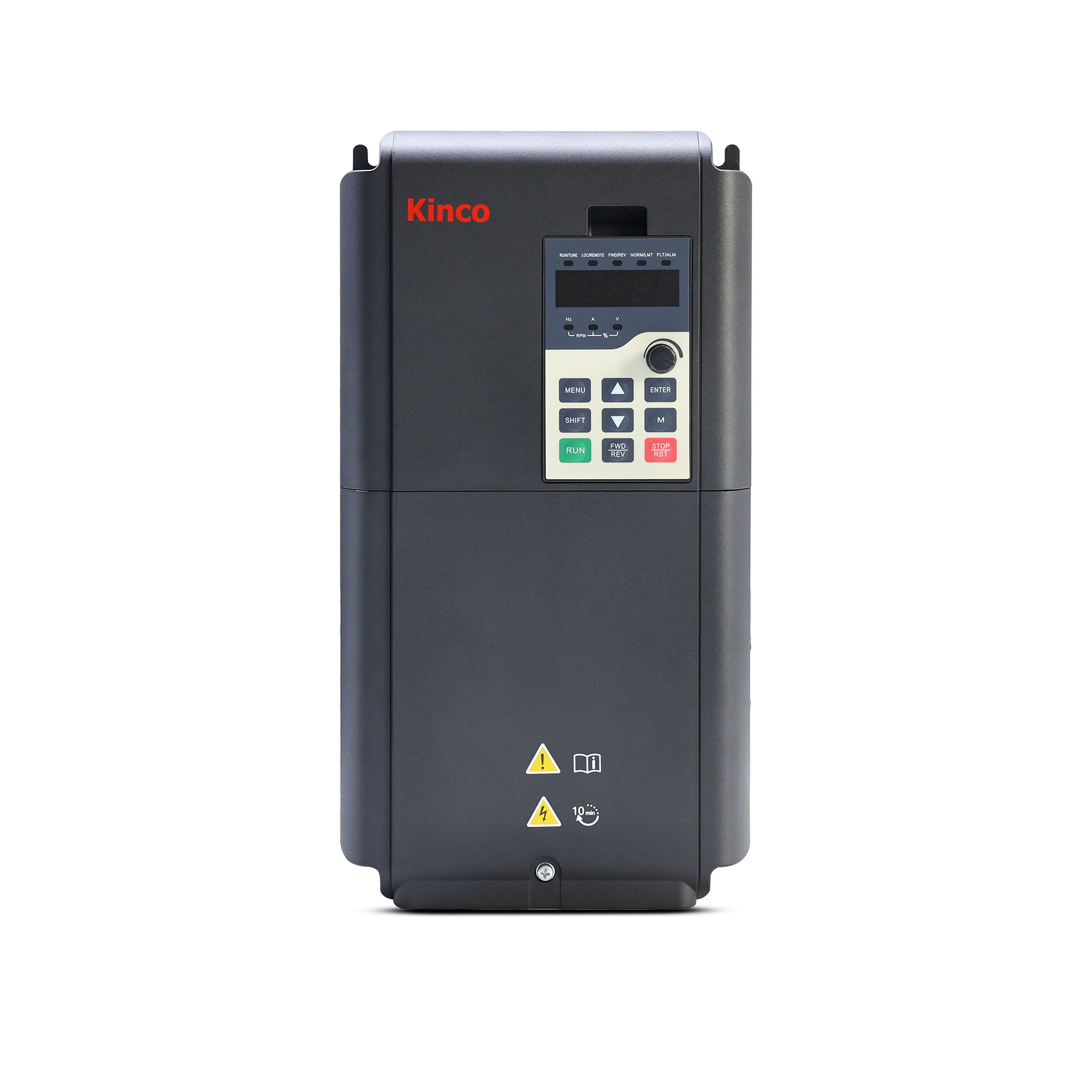
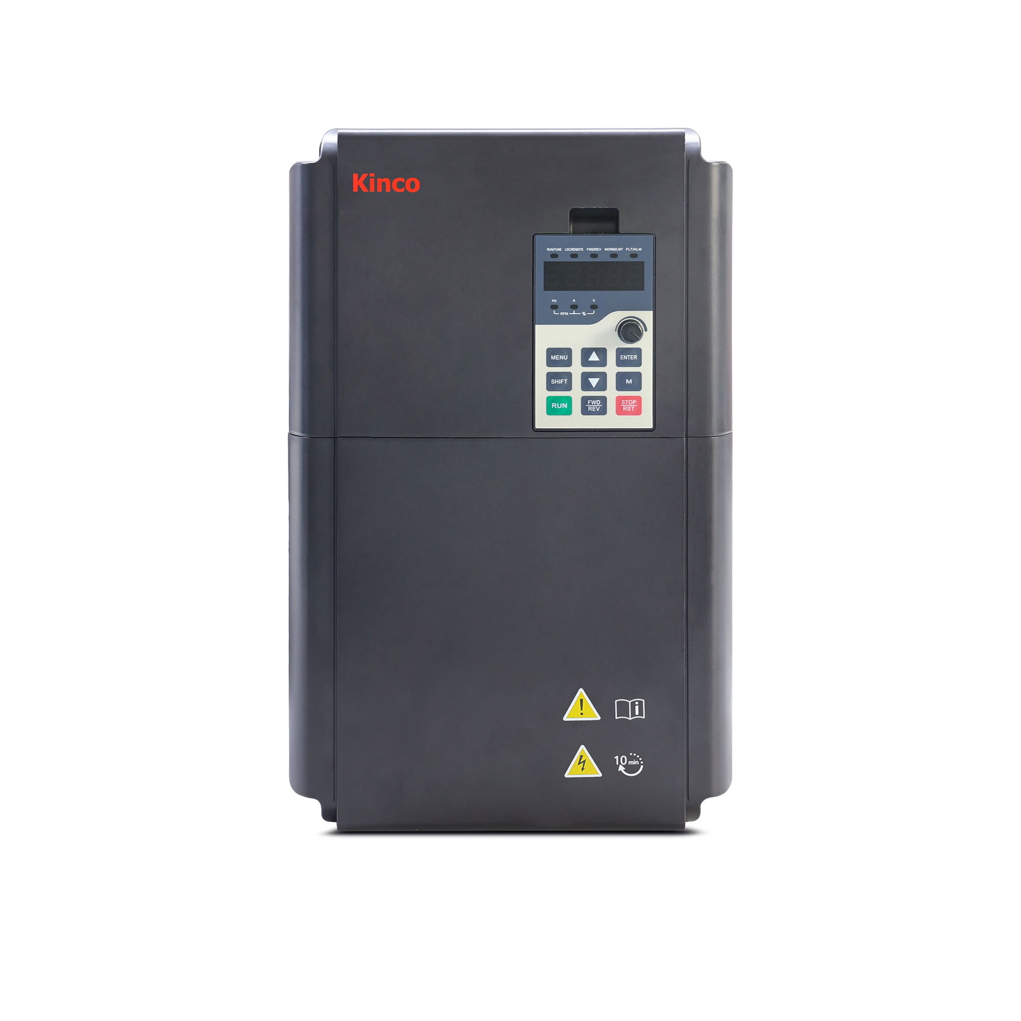
Kinco KC200 Frequenzumrichter
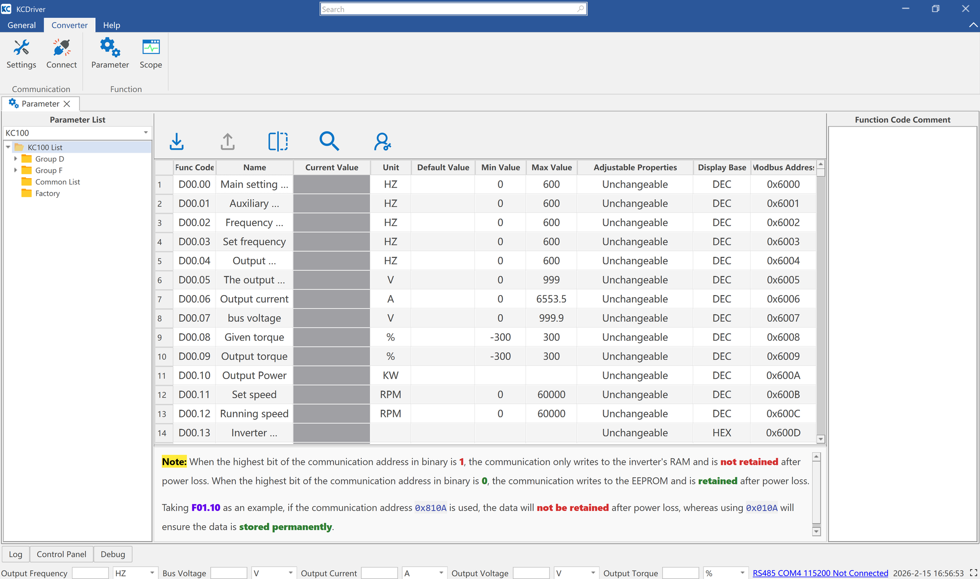
Passende Software
Zubehör