



%
discontinued
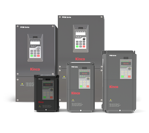
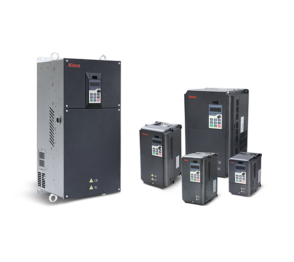
Kinco frequency converter FV20-4T-0150G (15 kW) three-phase 400 VAC
€300.00 *
€420.00
(28.57% saved)
⚠️ Remaining stock – this device is no longer manufactured.Kinco has discontinued the FV20 series. We are only selling the last units from our warehouse. Once they are gone, there will be no further supply.👉 Successor: Kinco KC200 – same frame size, improved functionality. For new installations and as a replacement we recommend the KC200.⚙️ FV20-4T-0150G: 15 kW, three-phase 400 V ACVector-controlled frequency inverter for standard drives such as conveyors, pumps, fans and machine axes. Robust and easy to set up – ideal as a 1:1 replacement for an FV20 already in service.Power: 15 kW at constant torque, output current 32 A, up to 18.5 kW for fan and pump loadsControl: sensorless vector control and V/f control; with the PG card also closed-loop vector control with encoderTorque: 150 % starting torque at 0.5 Hz, overload 150 % for 1 minute and 180 % for 10 secondsConnections: 6 digital inputs, 2 analog inputs, 2 analog outputs (0/4–20 mA or 0/2–10 V), 2 relay outputs, pulse output up to 100 kHz, RS-485 with Modbus RTUFeatures: Braking unit built in, keypad with potentiometer and parameter copyEnvironment: IP20, −10 °C to +40 °C (up to +50 °C with derating)
- Available
- Delivery Time : 3 bis 5 Tage
- Product Benefits 1: Vektorsteuerung
- Product Benefits 2: Autotuning der Motorparameter
- Product Benefits 3: Modbus RTU
- Product Benefits 4: 6 Digitaleingänge
- Product Benefits 5: 2 Analogeingänge
Available, delivery time: 3 bis 5 Tage
Preis exkl. MwSt., zzgl. Versandkosten

Speed feedback extension card (PG) for Kinco FV20 frequency inverter
This card is plugged onto the circuit board of the FV20 frequency inverters in order to detect the speed feedback of an encoder and to transfer it to the speed control of the motor.This increases the control quality of the speed control of the frequency inverter.The cover of the frequency inverter must be removed for installation.
- Available
- Delivery Time : 3 bis 5 Tage
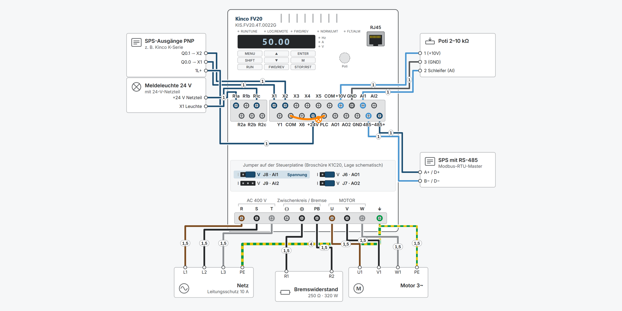
Kinco FV20 – Support, Wiring Diagram & Commissioning
Everything for your Kinco FV20 after purchase – for all 14 models in the Shop from 0.75 to 75 kW, single-phase 230 V and three-phase 400 V:Interactive wiring diagram: mains and motor, start/stop, preset speeds, setpoint, Modbus RTU, relay, run signal and braking resistor, with cable cross-sections and parametersFirst steps: commissioning in eleven steps, from the motor data to the first runOperation: keypad simulator to try out, with exercisesDimensions & mounting: dimensional drawing per model, drilling pattern, minimum clearances and a printable drilling templateDownloads: user manual, German brochure, catalogue, CE certificates and configuration softwareFree support from spstiger if you get stuck