



Kinco FV20 – Support, Wiring Diagram & Commissioning
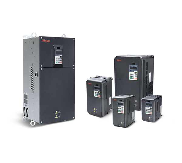
Everything for your Kinco FV20 after purchase – for all 14 models in the Shop from 0.75 to 75 kW, single-phase 230 V and three-phase 400 V:
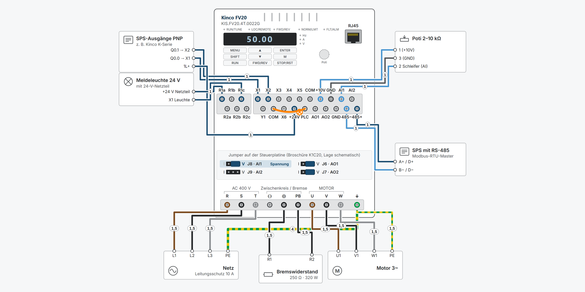
Interactive wiring diagram: mains and motor, start/stop, preset speeds, setpoint, Modbus RTU, relay, run signal and braking resistor, with cable cross-sections and parameters
First steps: commissioning in eleven steps, from the motor data to the first run
Operation: keypad simulator to try out, with exercises
Dimensions & mounting: dimensional drawing per model, drilling pattern, minimum clearances and a printable drilling template
Downloads: user manual, German brochure, catalogue, CE certificates and configuration software
Free support from spstiger if you get stuck
Keypad: keys, display and LEDs
MENU opens the menu for setting parameters – the most important key for programming. Try out the keypad here: set parameters, start and stop the motor, reset faults. The exercises guide you step by step through the most important procedures. Rest the mouse pointer on a key for a moment to see what it does right now.
Interactive wiring diagram
Tap a terminal or wire in the drawing to see details.
Terminal overview FV20
| Terminal | Group | mm² | Function |
|---|---|---|---|
| R1a | RELAIS | – | R1a–R1b NC contact, R1a–R1c NO contact. AC 250 V / 2 A (cos φ = 1), AC 250 V / 1 A (cos φ = 0.4), DC 30 V / 1 A. Function A6.16, factory 16 = fault. Designation and position according to brochure K1C20-2101 (2021); the 2019 manual calls the terminals Ra/Rb/Rc. |
| R1b | RELAIS | – | R1a–R1b is closed in the idle state. |
| R1c | RELAIS | – | R1a–R1c closes when the relay function is active. |
| R2a | RELAIS | – | R2a–R2b NC contact, R2a–R2c NO contact (brochure K1C20-2101, 2021). The 2019 manual does not describe relay 2: contact ratings and function parameter are missing, A6.17 is listed there as “reserved”. The function is probably selected via A6.17 (assumption, check on the device). |
| R2b | RELAIS | – | R2a–R2b is closed in the idle state. |
| R2c | RELAIS | – | R2a–R2c closes when the relay function is active. |
| X1 | STEUER | – | Optocoupler, bipolar (bridge rectifier), 2–30 V, input resistance 3.3 kΩ, max. 200 Hz. Function A6.00; according to manual chap. 6.7 factory 1 = forward (the parameter list in chap. 9 states 0 = no function). |
| X2 | STEUER | – | Optocoupler, bipolar (bridge rectifier), 2–30 V, input resistance 3.3 kΩ, max. 200 Hz. Function A6.01; according to chap. 6.7 factory 2 = reverse (parameter list: 0). |
| X3 | STEUER | – | Optocoupler, bipolar (bridge rectifier), 2–30 V, input resistance 3.3 kΩ, max. 200 Hz. Function A6.02; according to chap. 6.7 factory 6 = reset (parameter list: 0). |
| X4 | STEUER | – | Optocoupler, bipolar (bridge rectifier), 2–30 V, input resistance 3.3 kΩ, max. 200 Hz. Function A6.03; according to chap. 6.7 factory 27 = preset speed terminal 1 (parameter list: 0). |
| X5 | STEUER | – | Optocoupler, bipolar (bridge rectifier), 2–30 V, input resistance 3.3 kΩ, max. 200 Hz. Function A6.04; according to chap. 6.7 factory 28 = preset speed terminal 2 (parameter list: 0). |
| COM | STEUER | – | Reference of the internal 24 V supply, internally connected to the second COM terminal. Galvanically isolated from GND. Never short-circuit with +24V. |
| +10V | STEUER | – | Output +10 V, max. 5 mA, e.g. for a setpoint potentiometer (at least 2 kΩ, calculated from 10 V / 5 mA). |
| GND | STEUER | – | Reference for AI1, AI2, AO1, AO2 and +10V. Internally connected to the second GND terminal, galvanically isolated from COM. |
| AI1 | STEUER | – | 0–10 V (45 kΩ, resolution 1/4000) or 0–20 mA (resolution 1/2000), single-ended to GND. Selected via jumper AI1. Curve in group A3. |
| AI2 | STEUER | – | Like AI1, selected via jumper AI2. Factory: actual value input of the process controller (C1.02 = 1). |
| Y1 | STEUER | – | Open collector with optocoupler, switches to COM, max. 30 V DC / 50 mA. Function A6.14, factory 0 = inverter running. |
| COM | STEUER | – | Second COM terminal, reference for Y1 and the 24 V supply. Never short-circuit with +24V, otherwise the control board may be damaged. |
| X6 | STEUER | – | Like X1–X5, additionally pulse input up to 100 kHz (A0.02 = 4, maximum frequency A6.10). Function A6.05; according to chap. 6.7 factory 29 (parameter list: 0). |
| +24V | STEUER | – | 24 V DC, max. 200 mA for digital inputs and sensors. Linked to PLC at the factory. |
| PLC | STEUER | – | Linked to +24V at the factory: a contact between Xn and COM then switches the input. For PNP control or an external supply, remove the jumper (manual Fig. 4-8 to 4-12). |
| AO1 | STEUER | – | 0–10 V or 0/4–20 mA, selected via jumper AO1, factory voltage. Function A6.30 (factory 0 = none). For current, burden below 400 Ω. |
| AO2 | STEUER | – | Like AO1, selected via jumper AO2. Function A6.31. |
| GND | STEUER | – | Second GND terminal, reference for AO1 and AO2 (manual Fig. 4-4). |
| 485− | STEUER | – | Minus of the differential signal. Route twisted or shielded. |
| 485+ | STEUER | – | Plus of the differential signal. On the terminal strip 485− sits to the left of 485+ (brochure K1C20-2101, device photo). A terminating resistor is not described in the manual; for long cables connect 100–200 Ω in parallel at the master (chap. 10.3). |
| R / R (L) | LEISTUNG | – | Three-phase 380–440 V (permissible 320–460 V). Single-phase units (2S): L to R, N to T (manual chap. 4.1.2). Line protection 1.5–2 × input current (chap. 3.2.1). |
| S | LEISTUNG | – | Three-phase 380–440 V. Unused on single-phase units (2S). |
| T / T (N) | LEISTUNG | – | Three-phase 380–440 V. Single-phase units (2S): N to T. |
| ⊖ / +1 | LEISTUNG | – | Up to 45 kW: DC link minus, not for the braking resistor. 55 and 75 kW: +1, connection for an external DC reactor (manual Tab. 4-1). |
| ⊕ / +2 | LEISTUNG | – | Up to 45 kW: braking resistor between ⊕ and PB, the brake chopper is built in. 55 and 75 kW: +2, together with ⊖ connection of the external braking unit. |
| PB / ⊖ | LEISTUNG | – | Up to 45 kW: second terminal of the braking resistor, never connect to ⊖. 55 and 75 kW: DC link minus for the external braking unit. |
| U | LEISTUNG | – | Motor output. Never apply mains voltage to U/V/W; no capacitors or varistors at the output. |
| V | LEISTUNG | – | Motor output. Never apply mains voltage to U/V/W. |
| W | LEISTUNG | – | Motor output. Never apply mains voltage to U/V/W. |
| ⏚ | LEISTUNG | – | Connect PE first. Copper earthing conductor above 3.5 mm², earthing resistance below 10 Ω. Earth the inverter and the motor (manual chap. 4). |
| RJ45 | – | – | Socket for the remote keypad. Pin assignment according to brochure K1C20-2101 (2021): 1 = 485+, 2 = 485−, 5 = GND, 8 = +5 V; the 2019 manual states 2 = +5 V, 3 = 485+, 4 = 485−, 5 = GND. The PG card connects to the expansion interface J19. |
* Clamping range not stated in the manual, derived.
First steps with the Kinco FV20
Eleven steps from connecting to the first motor run: remove parameter protection, enter motor data, set start/stop and setpoint, adjust ramps. You only need digital inputs, outputs, Modbus and the braking resistor if your application uses them. The FV20 has been discontinued; its successor is the Kinco KC200 with its own parameter system.
Disconnect all supplies and wait at least 10 minutes until all LEDs on the keypad are off and the charge indicator has gone out. The voltage between ⊕ and ⊖ must be less than 36 V DC.
The FV20 has no STO. Implement safe motor shutdown on site with a contactor or safety circuit.
Always connect the protective earth (PE) first: copper over 3.5 mm², earth resistance below 10 Ω.
1Connect mains and motorRequired
Mains goes to R, S and T, the motor to U, V and W, plus PE at the inverter and motor. On the single-phase FV20-2S, L goes to R and N to T; S stays free.
The wiring diagram shows line protection and cross-sections for your model in the example “Mains and motor”. The manual has no table for this; the values are derived.
Circuit breaker: 1.5 to 2 times the rated current of the inverter. A universal-current-sensitive residual current device type B with 300 mA is recommended (manual chap. 3.2.1 and 4).
Up to 45 kW, an EMC filter is built in. Never apply mains voltage to U, V, W. From 100 m of motor cable, an output reactor is recommended.
Source: Manual chap. 3.2, 4.1; fv20/01-basis
2Keypad and parameter protectionRequired
According to the parameter list, only A0.03 can be changed at the factory: b4.02 = 1. Before you set other parameters, set b4.02 = 0. If no digit flashes when changing, the parameter is protected, can only be changed at standstill, or is a display value.
The menu has two levels: MENU opens the first function code A0.00, you select the code with ▲/▼, ENTER opens the value. SHIFT jumps to the highest digit, ▲/▼ changes it. ENTER saves and returns to the function code, MENU exits the menu.
Parameter Value Meaning b4.02 0 Parameter protection off: all parameters can be changed (parameter list: factory 1 = only A0.03 and b4.02) A0.00 0 No user password (factory). If “0.0.0.0.” appears after MENU, a password is set. b4.00 0 All keys unlocked (factory) b4.03 2 Load factory settings; 1 = clear fault memory only (only at standstill) The manual contradicts itself on some factory settings: chap. 6 gives b4.02 = 0, A0.04 = 0 and X1/X2 = forward/reverse, the parameter list in chap. 9 gives b4.02 = 1, A0.04 = 1 and X1–X6 without function. So always set these parameters explicitly.
Unlock the keypad: hold MENU and press ▼ once (chap. 5.1.3; Tab. 7-2 says hold ENTER and press ▼ three times). After power-up, the keypad is always unlocked.
Practise on the keypad: “Remove parameter protection: b4.02 = 0”Practise on the keypad: “Set setpoint frequency A0.03 from 50.00 to 30.00 Hz”
Source: Manual chap. 5.1, 6.14, 9; fv20/05-monitor
3Enter motor data and motor auto-tuningRequired
The values are on the motor's rating plate. All parameters in this step can only be changed at standstill.
Parameter Value Meaning b0.00 Rating plate Rated motor power in kW b0.01 Rating plate Rated motor voltage in V b0.02 Rating plate Rated motor current in A b0.03 Rating plate Rated motor frequency, usually 50.00 Hz in Europe b0.04 4 Number of motor poles (factory 4, step 2): 1440 min⁻¹ at 50 Hz is a 4-pole motor b0.05 Rating plate Rated motor speed in min⁻¹ A0.01 0, 1 or 2 Control mode: 0 = sensorless vector control, 1 = with encoder (PG card), 2 = V/f control (factory default) Motor auto-tuning
For rotating auto-tuning, uncouple the motor from the load.
A0.04 = 0 (start via the keypad) and A0.13 = 0 (automatic torque boost).
Enter b0.00 to b0.05 from the rating plate. The upper frequency limit A0.10 must not be below the rated motor frequency.
Set b0.11 = 2 (rotating) and confirm with ENTER. If the motor cannot run without load, use b0.11 = 1 (static).
Press RUN. Auto-tuning is complete when the RUN LED goes out; b0.06 to b0.10 are then calculated.
If auto-tuning fails, the inverter reports E024. In case of overcurrent or overvoltage during rotating auto-tuning, extend the ramp times (chap. 6.10).
Motor power and inverter power should match: according to the manual, at most 20 % smaller or 10 % larger.
Practise on the keypad: “Enter motor data and start motor auto-tuning”
Source: Manual chap. 6.10, 11.1; fv20/01-basis
4Set the start/stop sourceRequired
A0.04 defines where the run command comes from. You set the setpoint separately in step 5.
Parameter Value Meaning A0.04 0 Keypad: RUN and STOP/RST on the device, rotation direction A0.05 A0.04 1 Terminals: X1 forward (A6.00 = 1), X2 reverse (A6.01 = 2) A0.04 2 Communication: Modbus RTU/ASCII, see step 9 A6.09 0 Terminal control two-wire 1 (factory); 2/3 = three-wire. Caution with 4: starts immediately at power-up if the contact is closed. A1.05 0 Stop mode: 0 = ramp (factory), 1 = coast, 2 = ramp + DC brake PLC is the common terminal of X1–X6 and is jumpered to +24V by default: a contact between Xn and COM then switches the input. If a PLC with PNP outputs or an external 24 V supply controls the inputs, the jumper must be removed. Never short-circuit +24V and COM.
You assign the M key via b4.01, e.g. 0 = jog or 4 = switch rotation direction.
Show wiring “Start/stop via switch”Show wiring “Start/stop from PLC (NPN)”Show wiring “Start/stop from PLC (PNP)”
Practise on the keypad: “Start and stop the motor from the keypad”Practise on the keypad: “Set start/stop to the terminals”
Source: Manual chap. 4.2, 6.1, 6.7; fv20/02-io
5Set the setpointRequired
A0.02 defines where the frequency setpoint comes from, independent of the start/stop source. With A0.02 = 0, you change the frequency setpoint directly in the display with ▲/▼.
Parameter Value Meaning A0.02 0 Digital: start value A0.03, adjustable with ▲/▼ or UP/DN terminals (factory) A0.02 3 Potentiometer on the keypad A0.02 1 / 2 Analog input AI1 / AI2 (0–10 V or 0–20 mA, selected with jumper J8 / J9) A0.02 4 Pulse input X6 up to 100 kHz (A6.10) A0.03 50.00 Hz Digital setpoint (factory) A0.08 50.00 Hz Maximum frequency (factory, up to 300 Hz); reference for ramps and analog curve A0.10 / A0.11 50.00 / 0.00 Hz Upper and lower frequency limit (factory) You set the curve of the analog inputs in group A3; AI1 uses curve 1 by default (A3.01–A3.04). 100 % corresponds to 10 V or 20 mA. For 4–20 mA, therefore A3.03 = 20.00 % (calculated).
There is no Modbus setpoint in A0.02: it comes via register 0x3201 when bit 8 is set in the control word (step 9).
Show wiring “Setpoint via potentiometer”Show wiring “Setpoint 4–20 mA from PLC”
Practise on the keypad: “Adjust the setpoint frequency in the display with ▲/▼”Practise on the keypad: “Setpoint via the keypad potentiometer”
Source: Manual chap. 5.1.3, 6.1, 6.4; fv20/01-basis
6Set acceleration and deceleration timeRequired
The times refer to the ramp from 0 Hz to the maximum frequency A0.08. The factory default depends on the power rating.
Parameter Value Meaning A0.06 6.0 / 20.0 / 30.0 s Acceleration time 1: up to 2 kW 6.0 s, 30–45 kW 20.0 s, above that 30.0 s (factory). The manual gives no value for 2.2–22 kW. A0.07 same as A0.06 Deceleration time 1 (factory same as acceleration time) A4.00 0 Ramp shape: 0 = linear (factory), 1 = S-curve (A4.07–A4.10) If the inverter reports E001 (overcurrent) while accelerating, increase the acceleration time. For E005 (overvoltage while decelerating), increase the deceleration time or connect a braking resistor (step 10).
Times 2–4 are in A4.01–A4.06 and are selected via digital inputs (function 31/32).
Practise on the keypad: “Shorten acceleration time A0.06 to 3.0 s”
Source: Manual chap. 6.1, 6.5; fv20/01-basis
7Assign digital inputsOptional
The FV20 has six digital inputs X1–X6 (optocoupler, 2–30 V). X6 is also a pulse input up to 100 kHz. You set the function in A6.00 (X1) to A6.05 (X6), only at standstill. Two inputs must not have the same function.
Value Function Value Function 1 Forward 10 External stop (effective in every control mode) 2 Reverse 12 Coast to stop 3 / 4 Jog forward / reverse 13 / 14 Frequency up / down (UP/DN) 5 Three-wire control (A6.09 = 2/3) 27–30 Preset speed terminal 1–4 (C0.00–C0.14) 6 Fault reset (reset) 31 / 32 Select acceleration/deceleration time 1 / 2 7 External fault (reports E015) 9 Run inhibit (coast) Preset speeds in binary code (manual Tab. 6-2): terminal 1 = 1, terminal 2 = 2, terminal 3 = 4, terminal 4 = 8. If all selection terminals are off, the normal setpoint applies, i.e. A0.03 with A0.02 = 0 (factory 50.00 Hz).
A6.13 inverts the logic of individual inputs (factory: all positive). The complete function list is in the manual, Tab. 6-1.
Show wiring “Start/stop via switch”Show wiring “Preset speeds via switches”
Source: Manual chap. 6.7, Tab. 6-1/6-2; fv20/02-io
8Relay, Y1 and analog outputsOptional
Relay R1 (R1a–R1b NC, R1a–R1c NO) signals a fault at the factory. The transistor output Y1 signals “Inverter running” at the factory and switches to COM. AO1/AO2 output 0–10 V or 0/4–20 mA (jumper J6/J7, factory voltage).
Parameter Value Meaning A6.16 16 Relay R1 = fault (factory); 0 = running, 1 = frequency reached, 15 = ready A6.14 0 Y1 = inverter running (factory); same selection as A6.16, max. 30 V DC / 50 mA A6.30 / A6.31 0 Function AO1 / AO2 (factory 0 = none); 1 = output frequency, 5 = output current (0–2 × rated current) Relay contact AC 250 V / 2 A (cos φ = 1) or DC 30 V / 1 A. Fit inductive loads with a freewheeling diode, RC snubber or varistor.
With current output, keep the load below 400 Ω (chap. 6.7).
The second relay R2 (R2a–R2c) is shown in the 2021 brochure and catalogue, but not in the 2019 manual. Its function parameter is not described either, probably A6.17 (assumption, check on the device).
Show wiring “Fault signal via relay”Show wiring “Run signal to PLC (Y1)”
Source: Manual chap. 4.2, 6.7, Tab. 6-6/6-8; fv20/02-io
9Configure ModbusOptional
The FV20 speaks Modbus RTU and ASCII via RS-485 (terminals 485+ and 485−; on the strip 485− is on the left). For start/stop via the bus, set A0.04 = 2; it takes the setpoint via bit 8 in the control word.
Parameter Value Meaning b3.00 001 Ones: baud rate (1 = 9600, 2 = 19200, 3 = 38400), tens: format (0 = 8-N-2 RTU, 1 = 8-E-1 RTU, 2 = 8-O-1 RTU), factory 001 b3.01 5 Slave address 1–127 (factory 5; 0 = broadcast) b3.02 0.0 s Timeout monitoring (factory off); then E017 A0.04 2 Command source communication Modbus registers
Register Value Meaning 0x3200 0x01C7 Start with setpoint enable (bits 0–2 = 111, bit 6, 7, 8) 0x3200 0x01C6 / 0x00C5 Stop via ramp / coast 0x3200 0x0280 Fault reset 0x3201 5000 Frequency setpoint in 0.01 Hz: 5000 = 50.00 Hz 0x3305 / 0x3306 read Current frequency / output current (0.1 A) 0x3314 read Last fault You address parameters as group × 256 + number, e.g. A0.06 → 0x0006, b3.01 → 0x0D01. Written with function 0x06, the value is lost after mains off; with 0x41 it stays saved (chap. 10.5).
Chap. 10.2 gives 8-N-1 as factory setting; according to the table, b3.00 = 001 means 8-N-2. It is best to set both sides explicitly.
The manual does not describe a built-in termination resistor. For long cables, 100–200 Ω in parallel at 485+/485− of the master (chap. 10.3).
Show wiring “Modbus RTU to PLC”
Source: Manual chap. 10, 11.4; fv20/03-modbus
10Connect a braking resistorOptional
Up to 45 kW, the brake chopper is built in; the resistor goes to ⊕ and PB. The wiring diagram shows the recommended resistor for your model. 55 and 75 kW need an external braking unit at +2 and ⊖.
Parameter Value Meaning A1.17 1 Enable brake chopper (factory 0 = off, only at standstill) A1.16 720 V Switch-on threshold for 400 V units (factory; 2S: 380 V) A1.18 80.0 % Share of braking time in operating time (factory) b2.02 000 Ones digit 0: overvoltage stall off, according to the manual with a braking resistor connected (factory 001) Without A1.17 = 1, the resistor stays cold and the inverter reports E005 during fast braking.
Never connect ⊕ or PB to ⊖: this damages the brake chopper (chap. 1.2).
Show wiring “Braking resistor”
Source: Manual chap. 2.7, 6.2, 6.12; fv20/01-basis, fv20/06-schnellkonfig
11First runRequired
Common messages on the first run
Code Meaning Remedy E001–E003 Overcurrent while accelerating / decelerating / at constant speed Extend ramps, check motor data and load E005 Overvoltage while decelerating Extend deceleration time or braking resistor with A1.17 = 1 E008 / E009 Phase loss input / output Check mains supply cable or motor cable E013 / E014 Overload inverter / motor Check load and rated motor current b0.02 E015 External fault (input with function 7) Eliminate the cause, reset; no automatic reset E017 No communication with the master Check cable, b3.00, b3.01 and timeout b3.02 E024 Motor auto-tuning fault Check rating plate data and motor connection, repeat P.oFF Undervoltage in the DC link Check mains voltage The last three faults are stored in d1.00, d1.05 and d1.06, plus voltage, current and frequency at the last fault in d1.01–d1.03. The complete list is in the manual chap. 7.
Practise on the keypad: “Start and stop the motor from the keypad”Practise on the keypad: “Read and reset a fault”
Source: Manual chap. 5.3, 7; fv20/01-basis
Revision 1.0 · 29.09.2026 · Source: Kinco FV20 VFD User Manual (24.04.2019), prepared in spstiger vfd-konfig (fv20/01-basis, 02-io, 03-modbus, 04-funktionen, 06-schnellkonfig). The manufacturer manual and applicable standards take precedence; installation and commissioning by a qualified electrician only.
Dimensions and mounting
Dimensions and drilling pattern of the selected model. The drawing is schematic; the dimensions are taken from the 2021 FV20 brochure. Units built before 2021 have different housings from 5.5 kW; their dimensions are in the 2019 manual.
All models
| Item | Rating | W × H × D (mm) | Hole spacing (mm) | Hole ⌀ (mm) | Weight (kg) |
|---|---|---|---|---|---|
| KIS.FV20.2S.0022G | 2.2 kW · 1~ 230 V | 126 × 186 × 167 | 115 × 175 | 4.7 | 2 |
| KIS.FV20.4T.0007G | 0.75 kW · 3~ 400 V | ||||
| KIS.FV20.4T.0015G | 1.5 kW · 3~ 400 V | ||||
| KIS.FV20.4T.0022G | 2.2 kW · 3~ 400 V | ||||
| KIS.FV20.4T.0037G | 3.7 kW · 3~ 400 V | ||||
| KIS.FV20.4T.0055G | 5.5 kW · 3~ 400 V | 146 × 256 × 181 | 131 × 243 | 5.8 | 6 |
| KIS.FV20.4T.0075G | 7.5 kW · 3~ 400 V | ||||
| KIS.FV20.4T.0110G | 11 kW · 3~ 400 V | ||||
| KIS.FV20.4T.0150G | 15 kW · 3~ 400 V | 170 × 320 × 207 | 151 × 303 | 5.8 | 8 |
| KIS.FV20.4T.0220G | 22 kW · 3~ 400 V | ||||
| KIS.FV20.4T.0370G | 37 kW · 3~ 400 V | 225 × 360 × 224 | 206 × 341 | 6.5 | 9 |
| KIS.FV20.4T.0450G | 45 kW · 3~ 400 V | ||||
| KIS.FV20.4T.0550G | 55 kW · 3~ 400 V | 285 × 617 × 258 | 220 × 596 | 10 | 35 |
| KIS.FV20.4T.0750G | 75 kW · 3~ 400 V |
Mounting step by step
1Check the installation site
The FV20 belongs in a well-ventilated indoor location, usually a control cabinet (degree of protection IP20).
Ambient temperature −10 to +40 °C. From 40 to 50 °C only with derating and forced ventilation.
Humidity 5 to 95 %, non-condensing.
Vibration below 5.9 m/s² (0.6 g).
No direct sunlight, no dust or metal dust, no corrosive or flammable gases, no dripping water.
Altitude above 1000 m: 10 % less rated current per 1000 m (manual fig. 1-3, up to 3000 m).
2Keep the minimum clearances
The fan blows the cooling air upwards. To let it enter and leave freely, the drive needs space to walls, cable ducts and neighbouring devices.
Up to 45 kW: at least 50 mm at the sides, at least 100 mm above and below.
55 and 75 kW: at least 150 mm at the sides, at least 350 mm above and below.
3Mark and drill the holes
The FV20 is fixed with four screws. The top holes are closed, the bottom ones are slots open towards the edge. Up to 45 kW they sit in recesses at the housing corners, at 55 and 75 kW in lugs of the sheet-metal housing (brochure pages 5 and 6).
For the smallest housing (Ø 4.7 mm) the brochure recommends M4 screws. It gives no screw size for the other hole diameters.
The 1:1 drilling template helps with marking out. Print it at actual size (100 %) and check the 100 mm reference length with a ruler.
4Mount vertically
Mount the drive vertically so that the cooling air flows upwards as intended (manual chapter 3.1). The weight is listed with the dimensions.
5Several drives above each other
If two drives are mounted one above the other, fit an air baffle between them. It guides the warm exhaust air of the lower unit past the upper one (manual fig. 3-3).
6Keypad in the cabinet door (optional)
The manual shows an external keypad with a mounting frame for the cabinet door (figs. 2-4 and 2-5). It gives no door cut-out; 65 × 130 mm corresponds to the frame body (derived).
Keypad: 60 × 100 × 30.7 mm.
Mounting frame: 82 × 146 × 18.4 mm.
7Connect
Then connect mains, motor and PE. Cross-sections and fusing per model are shown in the wiring diagram.
Revision 1.0 · 29.09.2026 · Source: FV20 brochure/catalogue K1C20-2101 (2021), pages 5 and 6; installation notes FV20 User Manual (04/2019), chapters 2 and 3. The manufacturer manual and applicable standards take precedence; installation by a qualified electrician only.
Stuck?
Our support helps you free of charge. Tell us what you are planning and which model you use – via the contact form, by email or in the community forum.
Contact formEmail support@spstiger.deAsk in the community forum
More ways to contact us: Support contacts
Downloads
User manual, German brochure, catalogue, CE certificates and configuration software:
Kinco FV20 frequency inverters
Accessories
