


Kinco GK2 – Support, Wiring Diagram & Commissioning
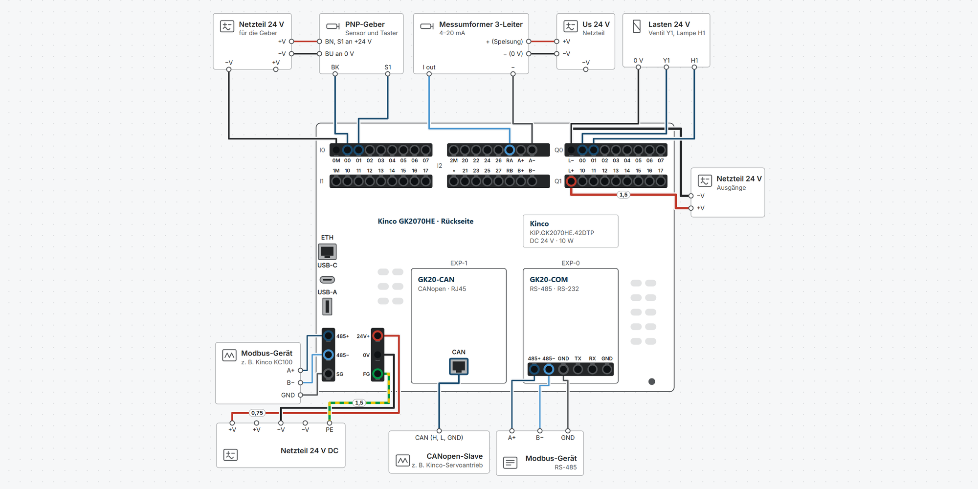
Everything for your Kinco GK2 after purchase – for the GK2070HE-42DTP with all GK20 expansion boards for slots EXP0 and EXP1:
Interactive wiring diagram: power supply, PNP and NPN sensors, encoder, 2-, 3- and 4-wire transmitters, 0–10 V, transistor outputs, Modbus RTU, Ethernet, USB and the GK20 boards (inputs and outputs, CANopen, RS-485/RS-232), with cable cross-sections and parameters
First steps: commissioning in ten steps, from first power-up to your first own program with an HMI screen
Dimensions & mounting: outside dimensions, panel cut-out and a printable cut-out template
Downloads: user manual, series catalogue and 2D and 3D drawings of the unit and expansion boards
Free support from spstiger if you get stuck
Interactive wiring diagram
Tap a terminal or wire in the drawing to see details.
Terminal overview GK2
| Terminal | Group | mm² | Function |
|---|---|---|---|
| 0M | Inputs I0 | 0.2–1.5* | Common connection of I0.0–I0.7: to 0 V for PNP sensors, to +24 V for NPN sensors. |
| 00 | Inputs I0 | 0.2–1.5* | Digital input 24 V DC, PNP or NPN, group I0 with reference 0M. High-speed counter input X0 (up to 200 kHz). Edge interrupt (rising/falling). |
| 01 | Inputs I0 | 0.2–1.5* | Digital input 24 V DC, PNP or NPN, group I0 with reference 0M. High-speed counter input X1 (up to 200 kHz). Edge interrupt (rising/falling). |
| 02 | Inputs I0 | 0.2–1.5* | Digital input 24 V DC, PNP or NPN, group I0 with reference 0M. High-speed counter input X2 (up to 200 kHz). Edge interrupt (rising/falling). |
| 03 | Inputs I0 | 0.2–1.5* | Digital input 24 V DC, PNP or NPN, group I0 with reference 0M. High-speed counter input X3 (up to 200 kHz). Edge interrupt (rising/falling). |
| 04 | Inputs I0 | 0.2–1.5* | Digital input 24 V DC, PNP or NPN, group I0 with reference 0M. High-speed counter input X4 (up to 200 kHz). |
| 05 | Inputs I0 | 0.2–1.5* | Digital input 24 V DC, PNP or NPN, group I0 with reference 0M. High-speed counter input X5 (up to 200 kHz). |
| 06 | Inputs I0 | 0.2–1.5* | Digital input 24 V DC, PNP or NPN, group I0 with reference 0M. High-speed counter input X6 (up to 200 kHz). |
| 07 | Inputs I0 | 0.2–1.5* | Digital input 24 V DC, PNP or NPN, group I0 with reference 0M. High-speed counter input X7 (up to 200 kHz). |
| 1M | Inputs I1 | 0.2–1.5* | Common connection of I1.0–I1.7: to 0 V for PNP sensors, to +24 V for NPN sensors. |
| 10 | Inputs I1 | 0.2–1.5* | Digital input 24 V DC, PNP or NPN, group I1 with reference 1M. |
| 11 | Inputs I1 | 0.2–1.5* | Digital input 24 V DC, PNP or NPN, group I1 with reference 1M. |
| 12 | Inputs I1 | 0.2–1.5* | Digital input 24 V DC, PNP or NPN, group I1 with reference 1M. |
| 13 | Inputs I1 | 0.2–1.5* | Digital input 24 V DC, PNP or NPN, group I1 with reference 1M. |
| 14 | Inputs I1 | 0.2–1.5* | Digital input 24 V DC, PNP or NPN, group I1 with reference 1M. |
| 15 | Inputs I1 | 0.2–1.5* | Digital input 24 V DC, PNP or NPN, group I1 with reference 1M. |
| 16 | Inputs I1 | 0.2–1.5* | Digital input 24 V DC, PNP or NPN, group I1 with reference 1M. |
| 17 | Inputs I1 | 0.2–1.5* | Digital input 24 V DC, PNP or NPN, group I1 with reference 1M. |
| 2M | I2 / analog A | 0.2–1.5* | Common connection of I2.0–I2.7 (upper and lower row): to 0 V for PNP sensors, to +24 V for NPN sensors. |
| 20 | I2 / analog A | 0.2–1.5* | Digital input 24 V DC, PNP or NPN, group I2 with reference 2M. |
| 22 | I2 / analog A | 0.2–1.5* | Digital input 24 V DC, PNP or NPN, group I2 with reference 2M. |
| 24 | I2 / analog A | 0.2–1.5* | Digital input 24 V DC, PNP or NPN, group I2 with reference 2M. |
| 26 | I2 / analog A | 0.2–1.5* | Digital input 24 V DC, PNP or NPN, group I2 with reference 2M. |
| RA | I2 / analog A | 0.2–1.5* | Feed in the current signal 0–20 mA or 4–20 mA here, return to A− (manual fig. 5.2-2 and 5.2-3). Input resistance 100 Ω. |
| A+ | I2 / analog A | 0.2–1.5* | Voltage signal 0–10 V or 1–5 V against A−. Input resistance 50 kΩ. Not used for current signals. |
| A− | I2 / analog A | 0.2–1.5* | Reference for the current and voltage signal of channel A. |
| ∗ | I2 / analog B | 0.2–1.5* | Terminal below 2M without function, do not connect. |
| 21 | I2 / analog B | 0.2–1.5* | Digital input 24 V DC, PNP or NPN, group I2 with reference 2M. |
| 23 | I2 / analog B | 0.2–1.5* | Digital input 24 V DC, PNP or NPN, group I2 with reference 2M. |
| 25 | I2 / analog B | 0.2–1.5* | Digital input 24 V DC, PNP or NPN, group I2 with reference 2M. |
| 27 | I2 / analog B | 0.2–1.5* | Digital input 24 V DC, PNP or NPN, group I2 with reference 2M. |
| RB | I2 / analog B | 0.2–1.5* | Feed in the current signal 0–20 mA or 4–20 mA here, return to B−. Input resistance 100 Ω. |
| B+ | I2 / analog B | 0.2–1.5* | Voltage signal 0–10 V or 1–5 V against B− (manual fig. 5.2-2). Input resistance 50 kΩ. |
| B− | I2 / analog B | 0.2–1.5* | Reference for the current and voltage signal of channel B. |
| L− | Outputs Q0 | 0.2–1.5* | 0 V of the output supply, common for Q0.0–Q1.7. Return of the loads. |
| 00 | Outputs Q0 | 0.2–1.5* | PNP transistor output 24 V DC, max. 500 mA, load to L− (0 V). |
| 01 | Outputs Q0 | 0.2–1.5* | PNP transistor output 24 V DC, max. 500 mA, load to L− (0 V). |
| 02 | Outputs Q0 | 0.2–1.5* | PNP transistor output 24 V DC, max. 500 mA, load to L− (0 V). |
| 03 | Outputs Q0 | 0.2–1.5* | PNP transistor output 24 V DC, max. 500 mA, load to L− (0 V). |
| 04 | Outputs Q0 | 0.2–1.5* | PNP transistor output 24 V DC, max. 500 mA, load to L− (0 V). |
| 05 | Outputs Q0 | 0.2–1.5* | PNP transistor output 24 V DC, max. 500 mA, load to L− (0 V). |
| 06 | Outputs Q0 | 0.2–1.5* | PNP transistor output 24 V DC, max. 500 mA, load to L− (0 V). |
| 07 | Outputs Q0 | 0.2–1.5* | PNP transistor output 24 V DC, max. 500 mA, load to L− (0 V). |
| L+ | Outputs Q1 | 0.2–1.5* | Supply of the 16 PNP outputs, 24 V DC. Without L+ the outputs do not switch. |
| 10 | Outputs Q1 | 0.2–1.5* | PNP transistor output 24 V DC, max. 500 mA, load to L− (0 V). |
| 11 | Outputs Q1 | 0.2–1.5* | PNP transistor output 24 V DC, max. 500 mA, load to L− (0 V). |
| 12 | Outputs Q1 | 0.2–1.5* | PNP transistor output 24 V DC, max. 500 mA, load to L− (0 V). |
| 13 | Outputs Q1 | 0.2–1.5* | PNP transistor output 24 V DC, max. 500 mA, load to L− (0 V). |
| 14 | Outputs Q1 | 0.2–1.5* | PNP transistor output 24 V DC, max. 500 mA, load to L− (0 V). |
| 15 | Outputs Q1 | 0.2–1.5* | PNP transistor output 24 V DC, max. 500 mA, load to L− (0 V). |
| 16 | Outputs Q1 | 0.2–1.5* | PNP transistor output 24 V DC, max. 500 mA, load to L− (0 V). |
| 17 | Outputs Q1 | 0.2–1.5* | PNP transistor output 24 V DC, max. 500 mA, load to L− (0 V). |
| 485+ | RS-485 (connector, left) | 0.2–1.5* | Built-in RS-485 of the PLC (galvanically isolated, up to 115.2 kbit/s): Modbus RTU master/slave, free protocol, programming. |
| 485− | RS-485 (connector, left) | 0.2–1.5* | Built-in RS-485 of the PLC, line B. |
| SG | RS-485 (connector, left) | 0.2–1.5* | Reference ground of the RS-485 interface. |
| 24V+ | Supply (connector, right) | 0.2–1.5* | 24 V DC (19.2–28.8 V), 10 W. Galvanically isolated, overcurrent, reverse-polarity and surge protection. |
| 0V | Supply (connector, right) | 0.2–1.5* | 0 V of the device supply. |
| FG | Supply (connector, right) | 0.2–1.5* | Earth connection (“protective ground” in the manual), to PE. |
| ETH | Ethernet | – | 10/100 Mbit/s, shared by HMI and PLC with separate IP addresses (built-in switch). Factory default HMI 192.168.0.253, PLC 192.168.0.252. |
| USB-C | USB-C | – | USB slave of the HMI: transfer the project and update the firmware. |
| USB-A | USB-A | – | USB host of the HMI: USB stick (project transfer, data), printer and other devices. |
* Clamping range not stated in the manual, derived.
First steps with the Kinco GK2070HE
The GK2070HE-42DTP combines a 7-inch touch operator panel (HMI) and a PLC with 42 inputs and outputs in one housing. You program each with its own software: the PLC with KincoBuilder Pro, the HMI screens with Kinco DTools Pro. This guide takes you from first power-up to your first own program with an HMI screen: power supply, connection, PLC and HMI project, expansion boards.
The GK2 needs 24 V DC from a power supply (permissible 19.2–28.8 V, 10 W). No 230 V mains connection.
Connect terminal FG to the earth or PE of the control cabinet.
Wire and plug in expansion boards only with the supply switched off.
Route control and communication cables at least 100 mm away from power cables.
1Power supply and first startRequired
The 6-pin connector at the bottom left carries the supply on the right (24V+, 0V, FG) and the PLC's RS-485 on the left (485+, 485−, SG).
The 16 transistor outputs also need their own supply: L+ to +24 V, L− to 0 V. Without L+ they do not switch.
After power-up the HMI starts and shows the stored project; a new device shows the Kinco start screen.
The inputs and outputs are on three pluggable push-in terminal blocks at the top of the rear: I0/I1, I2 with the analog inputs, and Q0/Q1.
Show wiring “24 V supply”Show wiring “Supplying the outputs”
Source: Manual ch. 3.2, 4, 5.1
2Two devices, two programsRequired
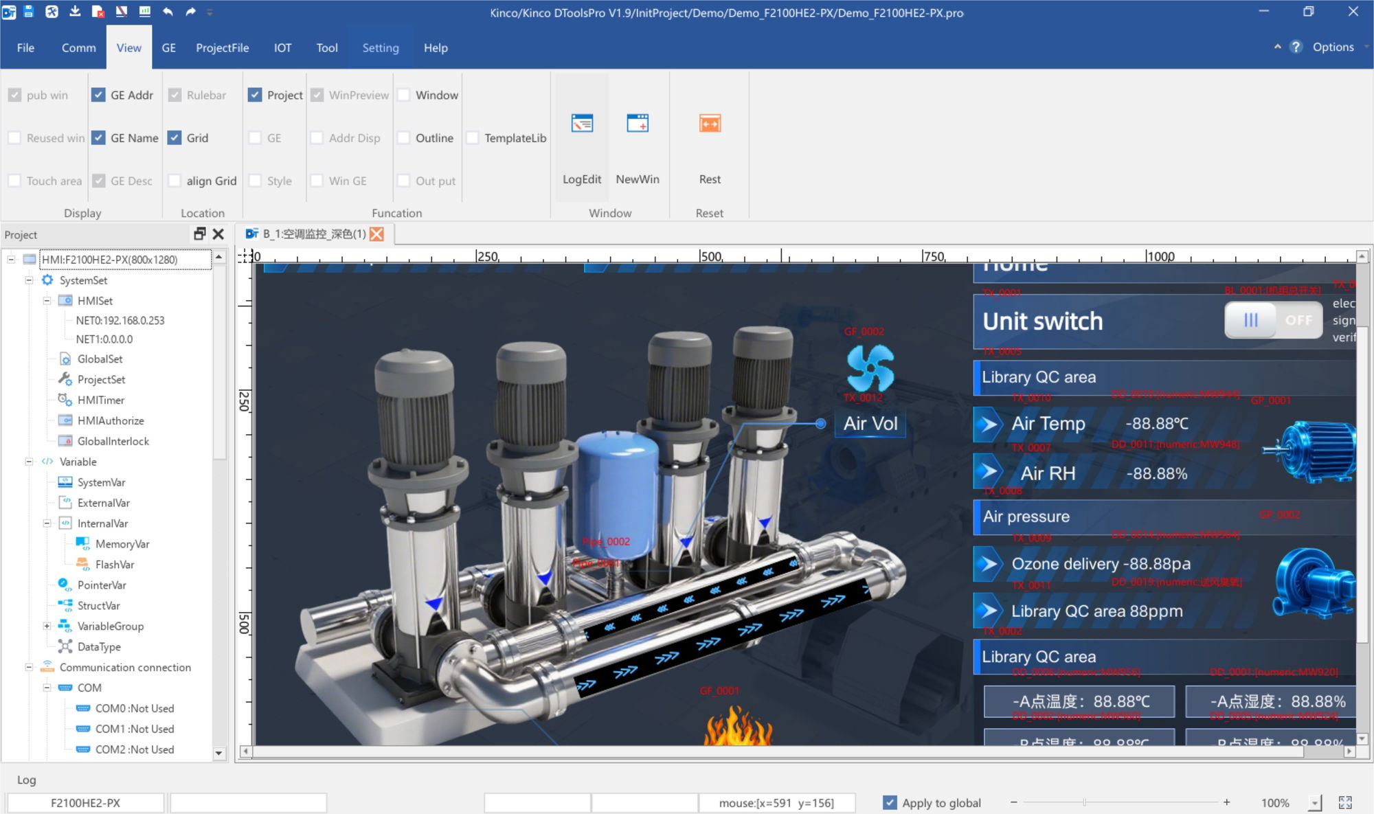
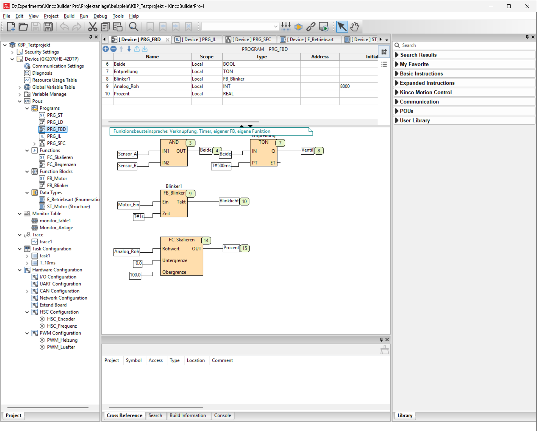
HMI and PLC work independently in the GK2 and exchange their data via an internal serial connection. That is why you need two programs: KincoBuilder Pro for the PLC (IEC 61131-3: ST, LD, FBD, SFC, IL) and Kinco DTools Pro for the HMI screens.
HMI and PLC share the Ethernet socket via a built-in switch; each device has its own IP address.
Task Software Connection Program and monitor the PLC, PLC firmware KincoBuilder Pro Ethernet or RS-485, also through the HMI Create and download HMI screens, HMI firmware Kinco DTools Pro (from V1.10.5) Ethernet, USB-C or USB stick KincoBuilder Pro is not the familiar KincoBuilder for MK, K2 or K6. For the GK2 you need Kinco's new Pro version.
The manual names DTools Pro V1.10.5 (build 260601) as the first version supporting the GK series.
KincoBuilder ProKinco DTools Pro
Source: Manual p. I–II, ch. 3.3, 8.1, 10.1
3Connect the PC to the GK2Required
The easiest way is to connect the PC via Ethernet. Ex works the two devices have these addresses:
HMI and PLC must never have the same IP address. If the HMI gets its address via DHCP, the PC needs addresses in both networks, or you put the PLC into the HMI's network.
How it works
Give your PC a fixed address in the same network, e.g. 192.168.0.10, mask 255.255.255.0.
In KincoBuilder Pro, select Ethernet under Communication Settings and click Scan. Click the PLC found; its device IP is taken over.
Connect with Connect in the toolbar. The connected device and the running program are highlighted in green.
Change the PLC's IP address: after scanning, use Modify Device Network Configuration. The PLC then restarts.
Device IP address ex works HMI 192.168.0.253 SPS 192.168.0.252 Alternatively, use the PLC's RS-485: the serial interface must be set to Configuration Service; this is the factory setting.
Source: Manual ch. 4, 8.3.1, 8.5, 10.7
4Create and download the PLC projectRequired
How it works
In KincoBuilder Pro, create a new project for the GK2070HE-42DTP.
Write the program and compile it (F11). Only continue when no errors are reported.
Download with F12. In the dialog, select software program and/or hardware configuration.
Tick Download project source code, otherwise the project cannot be uploaded from the controller later.
For retentive variables, decide: keep the values or reset them with Reinitialize Variables.
Changes to the hardware configuration (high-speed counters, PWM, interfaces, expansion boards) only take effect after the device restarts; KincoBuilder Pro restarts it when writing.
Program memory 60 kB, data memory 16 kB, of which 4 kB retentive (%MQW500 to %MQW2499, next step).
Source: Manual ch. 3.3, 8.3.2, 8.8
5Keep values after power-offRequired
According to the manual, the area %MQW500 to %MQW2499 is retentive, i.e. still there after switching off: 2000 words or 4 kB. Store everything that must survive a power failure there, e.g. setpoints, counter values or recipe data.
To do this, give the variable a fixed address in the global variable table, e.g. Sollwert AT %MQW500 : INT or, for 32 bits, Zaehler AT %MQD251 : DINT. A double word occupies two words, so %MQD251 uses %MQW502 and %MQW503.
When downloading
In the download dialog you decide what happens to the retentive values.
Retain the current value leaves them unchanged, e.g. when you only change the program.
Reinitialize Variables resets them to their initial values.
Memory Addresses Modbus After switching off Output words MQ %MQW0–%MQW499 4x0001–4x0500 not retentive Output words MQ, retentive %MQW500–%MQW2499 4x0501–4x2500 retained HMI and Modbus master reach the values via the same addresses: %MQW500 is 4x0501. If the master counts from 0, it is address 500.
Source: Manual ch. 3.3, 8.3.2, 11.1
6Create the HMI project and connect it to the PLCRequired
HMI and PLC talk to each other internally via Modbus RTU. A new project already contains the connection: under Communication connections › Serial ports you find COM0 with the driver Kinco PLC_Pro Serial(RTU), RS232, 115200 baud, 8 data bits, no parity, 1 stop bit, plus Device1 with station number 1. Leave it as it is.
That is why you reach the PLC values via Modbus addresses, not via the variable names from KincoBuilder Pro. A variable gets the register type and register address from the table below, e.g. 4X 1 for %MQW0.
How it works
In DTools Pro, use File › New Project, enter a name and select the GK2070HE as HMI model.
Under Variables › External variables › COM0[Device1] create a new variable: register type and register address from the table, plus the matching data type.
Create an element, e.g. Component › Switch › Word Setting with action Increment, and next to it a data display with the same variable.
Compile All, then test on the PC with Offline.
Select Download, enter Ethernet and the HMI's IP (ex works 192.168.0.253), download.
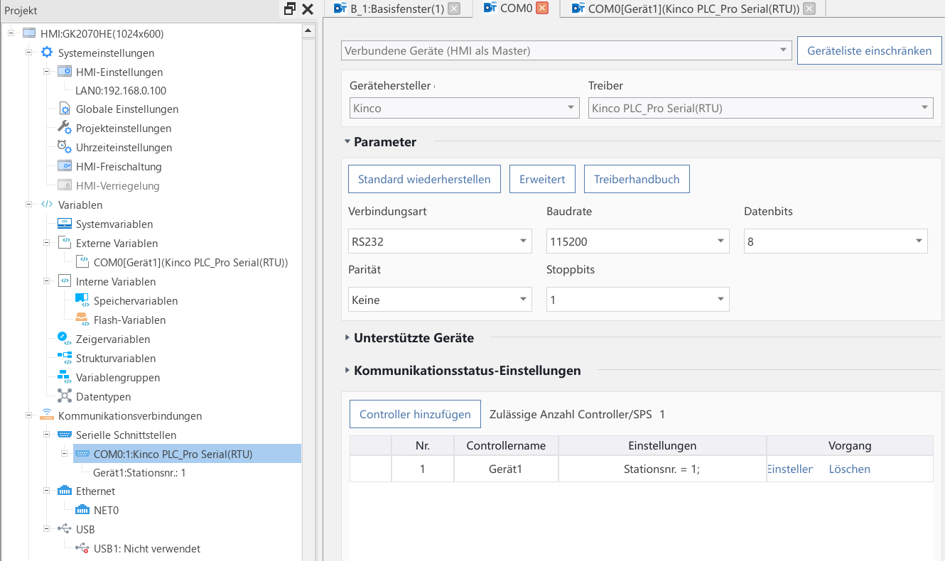
Preset at the factory: COM0 with driver Kinco PLC_Pro Serial(RTU), RS232, 115200 baud, Device1 with station number 1. 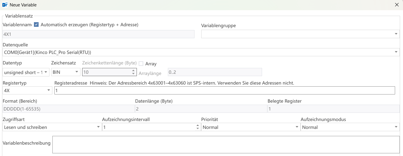
New variable for %MQW0: data source COM0[Device1], register type 4X, register address 1. Modbus mapping of the PLC
PLC addresses Content Modbus Access %I0.0–%I7.7 Digital inputs of the base unit 1x0001–1x0064 read %I8.0–%I39.7 Inputs of the expansion cards 1x0065–1x0320 read %I40.0–%I99.7 Intermediate area, bits 1x0321–1x0800 read %Q0.0–%Q7.7 Digital outputs of the base unit 0x0001–0x0064 read and write %Q8.0–%Q39.7 Outputs of the expansion cards 0x0065–0x0320 read and write %Q40.0–%Q99.7 Intermediate area, bits 0x0321–0x0800 read and write %MIW0–%MIW19 Analog inputs of the base unit 3x0001–3x0020 read %MIW20–%MIW147 Analog inputs of the expansion cards 3x0021–3x0148 read %MIW148–%MIW399 Intermediate area, words 3x0149–3x0400 read %MQW0–%MQW19 Analog outputs of the base unit 4x0001–4x0020 read and write %MQW20–%MQW147 Analog outputs of the expansion cards 4x0021–4x0148 read and write %MQW148–%MQW499 Intermediate area, words 4x0149–4x0500 read and write %MQW500–%MQW2499 Intermediate area, words, retentive 4x0501–4x2500 read and write Conversion: a bit %I n.b is 1x(8 · n + b + 1), e.g. %I2.7 = 1x0024, likewise %Q n.b = 0x(8 · n + b + 1). A word %MIW n is 3x(n + 1), %MQW n is 4x(n + 1). Calculated from the range limits in the manual table; 4x0001 = %MQW0 is also shown in the example in ch. 8.6.1.
A double word %MQD n occupies %MQW 2n and 2n + 1, so it starts at 4x(2n + 1). Select a 32-bit data type for it in DTools Pro.
According to the manual, you can use addresses that are not occupied by the base unit or the expansion cards as intermediate variables. KincoBuilder Pro shows which addresses a card occupies under hardware variables.
The PLC uses the range 4x63001–4x63060 internally, do not create variables there (note in DTools Pro).
Uploading a project from the HMI only works if it was permitted when downloading.
Source: Manual ch. 8.6.1, 10.1–10.8, 11.1; Kinco DTools Pro
7Connect inputs and outputsOptional
The 24 inputs are divided into three groups of eight: I0 with reference 0M, I1 with 1M and I2 with 2M. You wire each group separately as PNP (reference to 0 V) or NPN (reference to +24 V).
The 16 outputs are PNP transistors with max. 500 mA. The load is connected between output and L− (0 V).
The two analog inputs A and B measure 0/4–20 mA (signal to RA or RB, return to A− or B−) or 0–10 V and 1–5 V (to A+/A− or B+/B−).
Function Terminals Note High-speed counters up to 200 kHz Pairs X0/X1 … X6/X7 = I0.0/I0.1 … I0.6/I0.7 A/B encoders, in KincoBuilder Pro under HSC Configuration Edge interrupts I0.0–I0.3 rising and falling PWM outputs 4 channels, e.g. PWM0 on Y0 = Q0.0 in KincoBuilder Pro under PWM Configuration › PO Port Show wiring “PNP sensors on I0”Show wiring “Encoder on I0.0/I0.1”Show wiring “3-wire transmitter 4–20 mA”Show wiring “Valve and lamp on Q0”Show wiring “PWM on Q0.0”
Source: Manual ch. 3.4, 5.2, 8.8, 8.9
8Set up GK20 expansion boardsOptional
The rear has two slots for GK20 boards. Both take the I/O boards; the GK20-COM only fits EXP0, the GK20-CAN only EXP1. In the wiring diagram you plug in the boards at the top under “Plug in expansion boards”.
In KincoBuilder Pro the slots are named differently: EXP0 is slot 1, EXP1 is slot 2.
How it works
Switch off the supply, remove the slot cover, plug in the board.
In KincoBuilder Pro, open Expansion BD Board under Hardware Configuration and drag the board into the matching slot.
Set the board's options: filter time (04DI), behaviour at STOP (04DT), baud rate (CAN) or protocol per interface (COM).
Write the configuration. The board's addresses then appear under Hardware Variables.
Board Function Slot GK20-04DI 4 digital inputs, PNP or NPN EXP0 or EXP1 GK20-04DT 4 transistor outputs, 300 mA each EXP0 or EXP1 GK20-CAN CANopen master, RJ45 EXP1 only GK20-COM RS-485 and RS-232, Modbus RTU EXP0 only GK20-04XR, -02AI, -02AO, -02RD, -02TC Relay, analog, Pt100, thermocouple Assignment to follow as soon as Kinco publishes it If the PLC reports errors 300 to 305, a board is not responding or does not match the configuration: check slot and board type in KincoBuilder Pro.
Show wiring “GK20-04DI: PNP sensors”Show wiring “GK20-CAN: CANopen”Show wiring “GK20-COM: RS-485”
Source: Manual ch. 3.3, 8.10, 9.2
9Modbus RTU and Modbus TCPOptional
The PLC speaks Modbus via the built-in RS-485 (master or slave) and via Ethernet (server and client). As slave or server, a master reaches the areas I, Q, MI and MQ.
Enable the Modbus TCP server
In KincoBuilder Pro, open Modbus TCP Function under Hardware Configuration › Network Configuration.
On the server page, tick Server Enable, enter the port, write the configuration.
Test with a Modbus master: 4x0001 corresponds to %MQW0.
Range PLC addresses Modbus Inputs I %I0.0–%I99.7 1x0001–1x0800 Outputs Q %Q0.0–%Q99.7 0x0001–0x0800 Input words MI %MIW0–%MIW399 3x0001–3x0400 Output words MQ %MQW0–%MQW2499 4x0001–4x2500, retentive from %MQW500 For master operation there are the blocks ModBus_PORT1_MSG (RS-485) and ModBus_TCP_MSG (Ethernet). Error code 0 = done, 2 = not executed, 101 = communication failed, 104 = invalid input.
If your master counts addresses from 0, all addresses shift by one.
Show wiring “Modbus RTU on RS-485”
Source: Manual ch. 8.6, 8.7, 11.1
10Startup menu and diagnosticsOptional
You reach the HMI's startup menu by holding the screen pressed during power-up until the menu appears. There you find system settings (brightness, time, IP address), firmware update and touch calibration. After 20 seconds without input the project starts; Stop Countdown keeps the menu open.
PLC errors are stored in the system registers PLC_ErrID0 (severe error) and PLC_ErrID1 (minor error).
Code Meaning 104 Division by zero 125 Cycle time exceeded 300 / 303 Expansion board EXP0 / EXP1 not responding 302 / 305 Board type does not match the configuration 500–531 Analog channel over range or wire break 550 CANopen slave fault The complete error list is in manual ch. 9.2.
You update the PLC firmware in KincoBuilder Pro via the firmware update window (.bin file).
Source: Manual ch. 8.4, 9, 10.6
Revision 1.0 · 03.10.2026 · Source: Kinco GK2070HE User Manual V000 (07/2026), GK Series catalogue (08/2026). The manufacturer manual and applicable standards take precedence; installation and commissioning by a qualified electrician only.
Dimensions and mounting
The GK2070HE sits in a cut-out in the cabinet door or an operator console and is held from behind by four mounting clips. The drawing is projected from Kinco's 3D model; the plugged connectors on the rear are added from the Kinco dimension drawing. Dimensions rounded to whole millimetres.
Mounting step by step
1Check the installation site
The GK2070HE is intended for installation in cabinet doors and operator consoles. The front is protected to IP65, the rear to IP20 – it belongs inside the cabinet. The manual names these operating conditions:
Ambient temperature 0 to 55 °C, cooling by natural air circulation.
Humidity 10 to 95 %, non-condensing. Pollution degree 2, altitude up to 2000 m.
The manual does not state minimum clearances. Behind the panel, the device needs 56 mm depth with plugged connectors. Also plan space for cables, patch cables and USB plugs.
Route control and communication cables at least 100 mm away from power cables, in separate ducts.
2Mark and cut the panel cut-out
The panel cut-out is 192 × 138 mm. The cut-out template next to the drawing helps with marking. Print it at actual size (100 %) and check the 100 mm reference dimension with a ruler.
The manual does not state a tolerance or the permissible panel thickness. Rather cut slightly small and rework than cut too large. Deburr the edges so that the gasket seals properly.
Chips and drilling dust must not fall into the device's ventilation slots. Therefore cut the opening before the device is nearby.
3Insert and clamp
Four mounting clips with screw are supplied with the device for fastening.
Insert the device into the cut-out from the front. The gasket on the front frame stays in place.
Hook the mounting clips into the square slots on the housing from behind, either top and bottom or left and right.
Tighten the screws clockwise, 0.5 N·m is recommended. This keeps the front sealed and the housing does not distort.
4Removal
Disconnect all terminal blocks and the Ethernet cable so that nothing is damaged when lifting out.
Loosen the four screws anticlockwise and remove the mounting clips.
Lift the device straight forward out of the cut-out without knocking it.
Revision 1.0 · 03.10.2026 · Source: Kinco GK2070HE User Manual V000 (07/2026), ch. 3, 6 and 7; Kinco dimension drawing GK2070HE 2D and 3D model GK2070HE-3D. The manufacturer manual and applicable standards take precedence; installation by a qualified electrician only.
Stuck?
Our support helps you free of charge. Tell us what you are planning and which model you use – via the contact form, by email or in the community forum.
Contact formEmail support@spstiger.deAsk in the community forum
More ways to contact us: Support contacts
We have compiled and checked this page carefully from the manufacturer’s documentation. Even so, an error may have slipped in. The manufacturer’s manual and the applicable standards always take precedence. Spotted something? Let us know – we’ll be glad to fix it.
Downloads
User manual, series catalogue and 2D and 3D drawings of the unit and expansion boards:
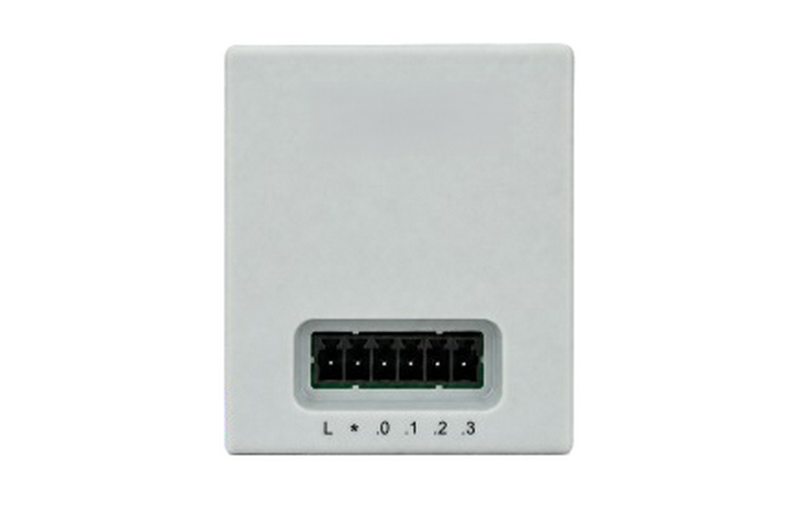
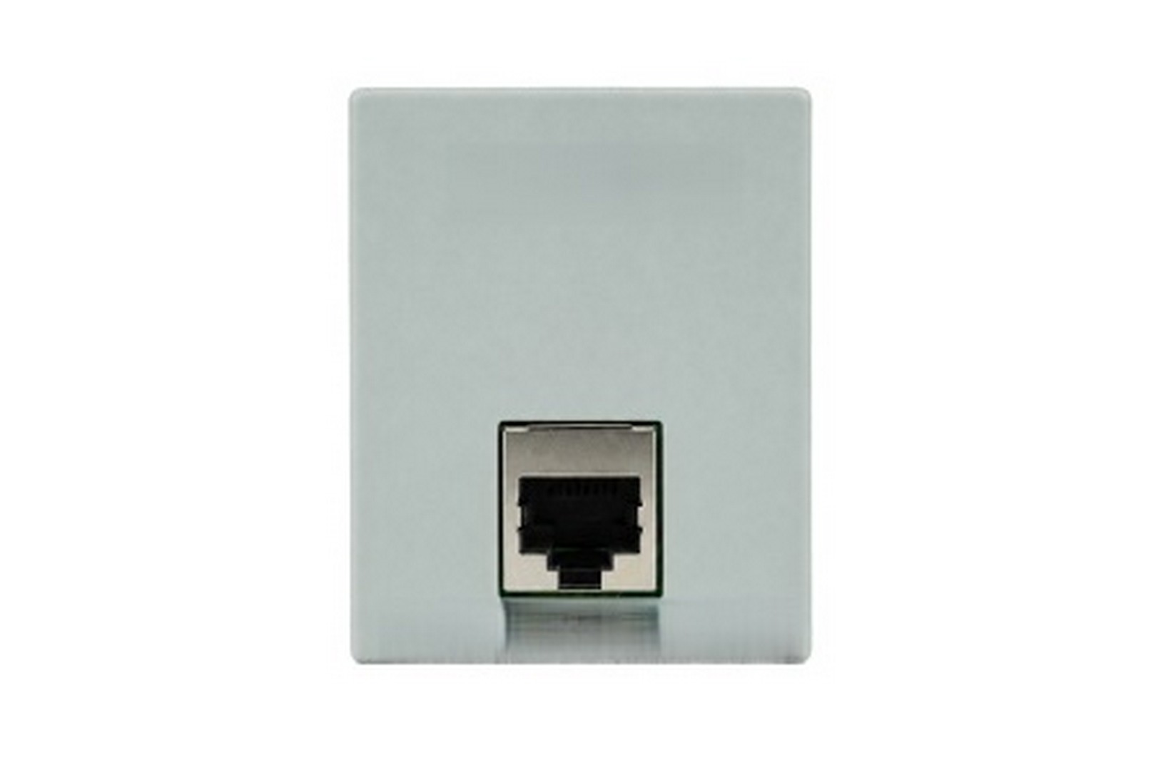
Kinco GK2 HMI with PLC and GK20 boards

Compatible software