


Solidot MT4 – Support, Wiring Diagram & Commissioning
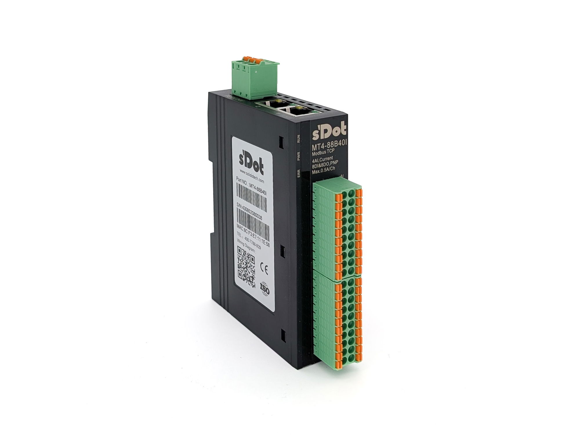
Everything for your Solidot MT4 after purchase – for all 15 models in the Shop: digital with 16 or 32 channels, analog with four or eight channels and the mixed MT4-88B40I:
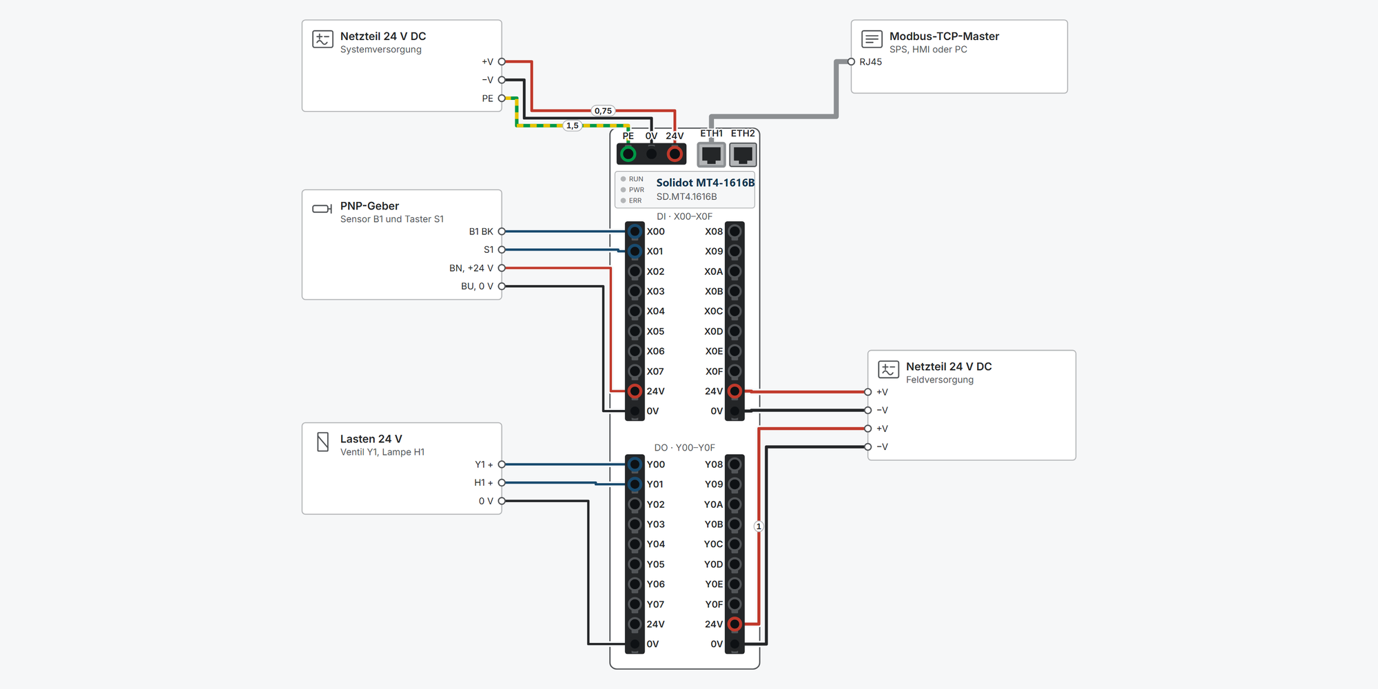
Interactive wiring diagram: system and field supply, PNP sensors, loads, 2-, 3- and 4-wire transmitters, analog output to a drive, Modbus TCP and daisy chain via the built-in switch, with cable cross-sections and parameters
Modbus & IP: factory IP, port and the address of every channel for your model
First steps: commissioning in eleven steps, from the DIN rail to the first signal in your controller
Dimensions & mounting: outside dimensions, DIN rail and minimum clearances
Downloads: user manual, MT4-88B40I manual (German), 2D and 3D drawings and EPLAN macros
Free support from spstiger if you get stuck
Interactive wiring diagram
Tap a terminal or wire in the drawing to see details.
Terminal overview MT4
| Terminal | Group | mm² | Function |
|---|---|---|---|
| PE | Versorgung | 0.3–1.5 | Earth. Connect PE securely to earth (manual ch. 6.2). |
| 0V | Versorgung | 0.3–1.5 | 0 V of the system supply. |
| 24V | Versorgung | 0.3–1.5 | System supply +24 V DC (18–30 V) for the module electronics. Keep it separate from the field supply of the inputs and outputs. |
| ETH1 | Ethernet | – | Modbus TCP, 100 Mbit/s, RJ45. Both sockets are connected to the built-in switch: one goes to the master, the other to the next module. Cable Cat. 5 or better, shielded (STP) recommended, max. 100 m between two devices. |
| ETH2 | Ethernet | – | Modbus TCP, 100 Mbit/s, RJ45. Both sockets are connected to the built-in switch: one goes to the master, the other to the next module. Cable Cat. 5 or better, shielded (STP) recommended, max. 100 m between two devices. |
| X00 | Block A Kl. 1–10 | 0.3–1 | Digital input X00, PNP: “1” at 15–30 V, “0” at −3…+3 V referred to 0 V, 4 mA, filter 3 ms, optically isolated. Modbus: 1x discrete input, address 10001 (protocol 0, FC 02). |
| X01 | Block A Kl. 1–10 | 0.3–1 | Digital input X01, PNP: “1” at 15–30 V, “0” at −3…+3 V referred to 0 V, 4 mA, filter 3 ms, optically isolated. Modbus: 1x discrete input, address 10002 (protocol 1, FC 02). |
| X02 | Block A Kl. 1–10 | 0.3–1 | Digital input X02, PNP: “1” at 15–30 V, “0” at −3…+3 V referred to 0 V, 4 mA, filter 3 ms, optically isolated. Modbus: 1x discrete input, address 10003 (protocol 2, FC 02). |
| X03 | Block A Kl. 1–10 | 0.3–1 | Digital input X03, PNP: “1” at 15–30 V, “0” at −3…+3 V referred to 0 V, 4 mA, filter 3 ms, optically isolated. Modbus: 1x discrete input, address 10004 (protocol 3, FC 02). |
| X04 | Block A Kl. 1–10 | 0.3–1 | Digital input X04, PNP: “1” at 15–30 V, “0” at −3…+3 V referred to 0 V, 4 mA, filter 3 ms, optically isolated. Modbus: 1x discrete input, address 10005 (protocol 4, FC 02). |
| X05 | Block A Kl. 1–10 | 0.3–1 | Digital input X05, PNP: “1” at 15–30 V, “0” at −3…+3 V referred to 0 V, 4 mA, filter 3 ms, optically isolated. Modbus: 1x discrete input, address 10006 (protocol 5, FC 02). |
| X06 | Block A Kl. 1–10 | 0.3–1 | Digital input X06, PNP: “1” at 15–30 V, “0” at −3…+3 V referred to 0 V, 4 mA, filter 3 ms, optically isolated. Modbus: 1x discrete input, address 10007 (protocol 6, FC 02). |
| X07 | Block A Kl. 1–10 | 0.3–1 | Digital input X07, PNP: “1” at 15–30 V, “0” at −3…+3 V referred to 0 V, 4 mA, filter 3 ms, optically isolated. Modbus: 1x discrete input, address 10008 (protocol 7, FC 02). |
| 24V | Block A Kl. 1–10 | 0.3–1 | Field supply +24 V DC (18–30 V) of block DI. Terminals 9 and 19 are connected internally. |
| 0V | Block A Kl. 1–10 | 0.3–1 | 0 V of the field supply. Terminals 10 and 20 are connected internally. |
| X08 | Block A Kl. 11–20 | 0.3–1 | Digital input X08, PNP: “1” at 15–30 V, “0” at −3…+3 V referred to 0 V, 4 mA, filter 3 ms, optically isolated. Modbus: 1x discrete input, address 10009 (protocol 8, FC 02). |
| X09 | Block A Kl. 11–20 | 0.3–1 | Digital input X09, PNP: “1” at 15–30 V, “0” at −3…+3 V referred to 0 V, 4 mA, filter 3 ms, optically isolated. Modbus: 1x discrete input, address 10010 (protocol 9, FC 02). |
| X0A | Block A Kl. 11–20 | 0.3–1 | Digital input X0A, PNP: “1” at 15–30 V, “0” at −3…+3 V referred to 0 V, 4 mA, filter 3 ms, optically isolated. Modbus: 1x discrete input, address 10011 (protocol 10, FC 02). |
| X0B | Block A Kl. 11–20 | 0.3–1 | Digital input X0B, PNP: “1” at 15–30 V, “0” at −3…+3 V referred to 0 V, 4 mA, filter 3 ms, optically isolated. Modbus: 1x discrete input, address 10012 (protocol 11, FC 02). |
| X0C | Block A Kl. 11–20 | 0.3–1 | Digital input X0C, PNP: “1” at 15–30 V, “0” at −3…+3 V referred to 0 V, 4 mA, filter 3 ms, optically isolated. Modbus: 1x discrete input, address 10013 (protocol 12, FC 02). |
| X0D | Block A Kl. 11–20 | 0.3–1 | Digital input X0D, PNP: “1” at 15–30 V, “0” at −3…+3 V referred to 0 V, 4 mA, filter 3 ms, optically isolated. Modbus: 1x discrete input, address 10014 (protocol 13, FC 02). |
| X0E | Block A Kl. 11–20 | 0.3–1 | Digital input X0E, PNP: “1” at 15–30 V, “0” at −3…+3 V referred to 0 V, 4 mA, filter 3 ms, optically isolated. Modbus: 1x discrete input, address 10015 (protocol 14, FC 02). |
| X0F | Block A Kl. 11–20 | 0.3–1 | Digital input X0F, PNP: “1” at 15–30 V, “0” at −3…+3 V referred to 0 V, 4 mA, filter 3 ms, optically isolated. Modbus: 1x discrete input, address 10016 (protocol 15, FC 02). |
| 24V | Block A Kl. 11–20 | 0.3–1 | Field supply +24 V DC (18–30 V) of block DI. Terminals 9 and 19 are connected internally. |
| 0V | Block A Kl. 11–20 | 0.3–1 | 0 V of the field supply. Terminals 10 and 20 are connected internally. |
| Y00 | Block B Kl. 1–10 | 0.3–1 | Digital output Y00, PNP: switches +24 V to the load, max. 500 mA, resistive and inductive loads, protected against overvoltage and overcurrent. Modbus: 0x coil, address 00065 (protocol 64, FC 15). |
| Y01 | Block B Kl. 1–10 | 0.3–1 | Digital output Y01, PNP: switches +24 V to the load, max. 500 mA, resistive and inductive loads, protected against overvoltage and overcurrent. Modbus: 0x coil, address 00066 (protocol 65, FC 15). |
| Y02 | Block B Kl. 1–10 | 0.3–1 | Digital output Y02, PNP: switches +24 V to the load, max. 500 mA, resistive and inductive loads, protected against overvoltage and overcurrent. Modbus: 0x coil, address 00067 (protocol 66, FC 15). |
| Y03 | Block B Kl. 1–10 | 0.3–1 | Digital output Y03, PNP: switches +24 V to the load, max. 500 mA, resistive and inductive loads, protected against overvoltage and overcurrent. Modbus: 0x coil, address 00068 (protocol 67, FC 15). |
| Y04 | Block B Kl. 1–10 | 0.3–1 | Digital output Y04, PNP: switches +24 V to the load, max. 500 mA, resistive and inductive loads, protected against overvoltage and overcurrent. Modbus: 0x coil, address 00069 (protocol 68, FC 15). |
| Y05 | Block B Kl. 1–10 | 0.3–1 | Digital output Y05, PNP: switches +24 V to the load, max. 500 mA, resistive and inductive loads, protected against overvoltage and overcurrent. Modbus: 0x coil, address 00070 (protocol 69, FC 15). |
| Y06 | Block B Kl. 1–10 | 0.3–1 | Digital output Y06, PNP: switches +24 V to the load, max. 500 mA, resistive and inductive loads, protected against overvoltage and overcurrent. Modbus: 0x coil, address 00071 (protocol 70, FC 15). |
| Y07 | Block B Kl. 1–10 | 0.3–1 | Digital output Y07, PNP: switches +24 V to the load, max. 500 mA, resistive and inductive loads, protected against overvoltage and overcurrent. Modbus: 0x coil, address 00072 (protocol 71, FC 15). |
| 24V | Block B Kl. 1–10 | 0.3–1 | Field supply +24 V DC (18–30 V) of block DO. Terminals 9 and 19 are connected internally. |
| 0V | Block B Kl. 1–10 | 0.3–1 | 0 V of the field supply. Terminals 10 and 20 are connected internally. |
| Y08 | Block B Kl. 11–20 | 0.3–1 | Digital output Y08, PNP: switches +24 V to the load, max. 500 mA, resistive and inductive loads, protected against overvoltage and overcurrent. Modbus: 0x coil, address 00073 (protocol 72, FC 15). |
| Y09 | Block B Kl. 11–20 | 0.3–1 | Digital output Y09, PNP: switches +24 V to the load, max. 500 mA, resistive and inductive loads, protected against overvoltage and overcurrent. Modbus: 0x coil, address 00074 (protocol 73, FC 15). |
| Y0A | Block B Kl. 11–20 | 0.3–1 | Digital output Y0A, PNP: switches +24 V to the load, max. 500 mA, resistive and inductive loads, protected against overvoltage and overcurrent. Modbus: 0x coil, address 00075 (protocol 74, FC 15). |
| Y0B | Block B Kl. 11–20 | 0.3–1 | Digital output Y0B, PNP: switches +24 V to the load, max. 500 mA, resistive and inductive loads, protected against overvoltage and overcurrent. Modbus: 0x coil, address 00076 (protocol 75, FC 15). |
| Y0C | Block B Kl. 11–20 | 0.3–1 | Digital output Y0C, PNP: switches +24 V to the load, max. 500 mA, resistive and inductive loads, protected against overvoltage and overcurrent. Modbus: 0x coil, address 00077 (protocol 76, FC 15). |
| Y0D | Block B Kl. 11–20 | 0.3–1 | Digital output Y0D, PNP: switches +24 V to the load, max. 500 mA, resistive and inductive loads, protected against overvoltage and overcurrent. Modbus: 0x coil, address 00078 (protocol 77, FC 15). |
| Y0E | Block B Kl. 11–20 | 0.3–1 | Digital output Y0E, PNP: switches +24 V to the load, max. 500 mA, resistive and inductive loads, protected against overvoltage and overcurrent. Modbus: 0x coil, address 00079 (protocol 78, FC 15). |
| Y0F | Block B Kl. 11–20 | 0.3–1 | Digital output Y0F, PNP: switches +24 V to the load, max. 500 mA, resistive and inductive loads, protected against overvoltage and overcurrent. Modbus: 0x coil, address 00080 (protocol 79, FC 15). |
| 24V | Block B Kl. 11–20 | 0.3–1 | Field supply +24 V DC (18–30 V) of block DO. Terminals 9 and 19 are connected internally. |
| 0V | Block B Kl. 11–20 | 0.3–1 | 0 V of the field supply. Terminals 10 and 20 are connected internally. |
* Clamping range not stated in the manual, derived.
Modbus TCP: IP address and channel addresses
This is how you find the MT4 in your controller: out of the box every module listens on 192.168.1.120, port 502. Below you find all channels for your model – in the notation your software uses.
Factory setting
- IP address
- 192.168.1.120
- Subnet mask
- 255.255.255.0
- Gateway
- 192.168.1.1
- Port
- 502
- Unit ID
- 1
- All modules ship with the same address. Connect new modules one after the other and change the address before the next one goes on the network.
- Unit ID 1 and port 502 come from the CODESYS example in the manual (ch. 7.5).
Changing the IP address
- Connect your PC to ETH1 or ETH2 and set it to a free address in the 192.168.1.x network, e.g. 192.168.1.10 / 255.255.255.0 (example).
- Check: in the command prompt, run ping 192.168.1.120.
- Open http://192.168.1.120 in your browser, enter the new IP address, mask and gateway, save.
- Restart the module and check it under the new address.
Forgot the address?
- With the module switched on, press the reset button for 1 s (insulated tool thinner than 1.2 mm).
- RUN/ERR flash and then stay lit.
- Switch the module off and on again: it has 192.168.1.120 again.
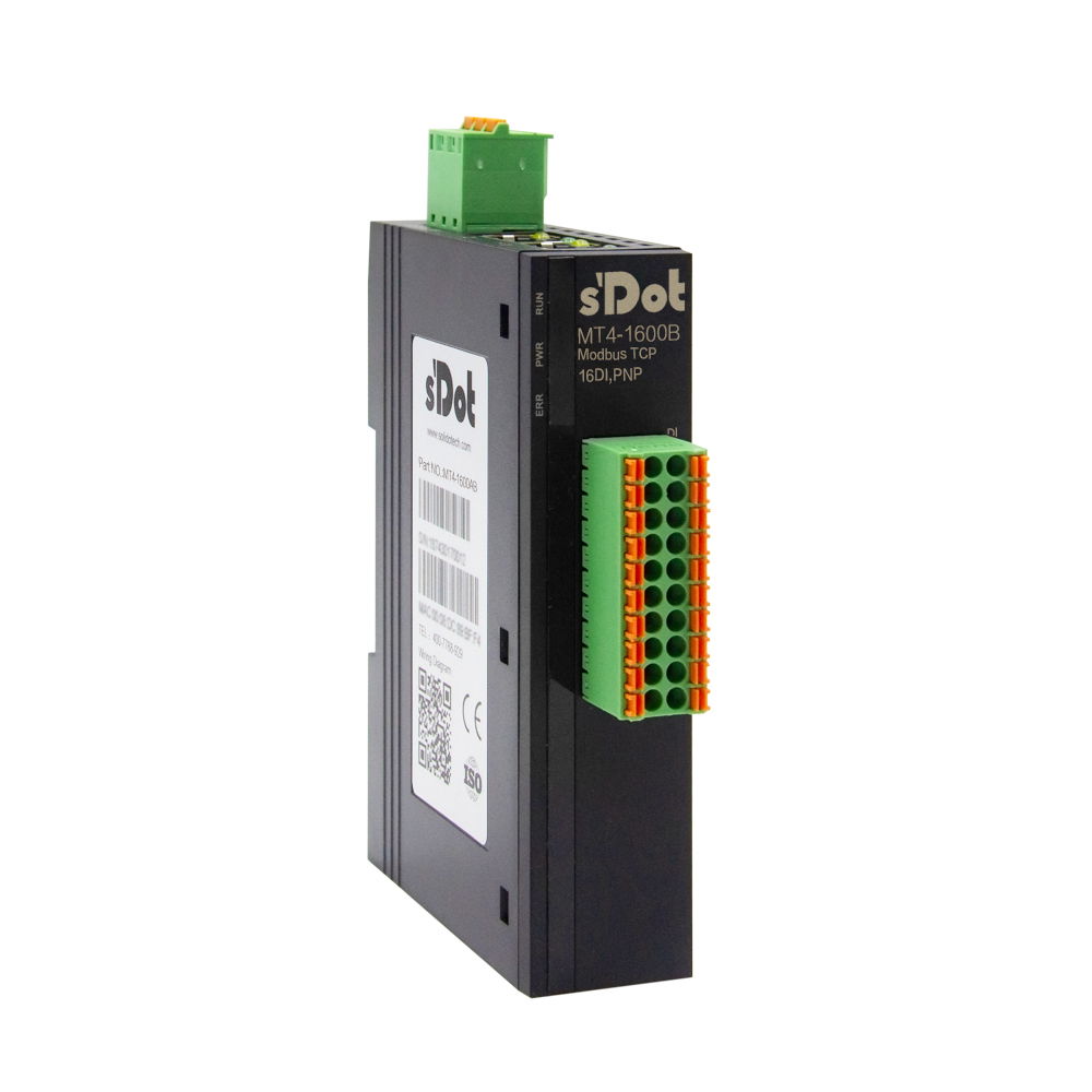
MT4-1600B · 16 DI PNP
All at once
| Task | from address | Count |
|---|---|---|
| Read all inputs | 100011000011x 11x 0 | 16 |
Digital inputs X00–X0F
| Terminal | Signal | Address (1x discrete input) |
|---|---|---|
| 1 | X00 | 100011000011x 11x 0 |
| 2 | X01 | 100021000021x 21x 1 |
| 3 | X02 | 100031000031x 31x 2 |
| 4 | X03 | 100041000041x 41x 3 |
| 5 | X04 | 100051000051x 51x 4 |
| 6 | X05 | 100061000061x 61x 5 |
| 7 | X06 | 100071000071x 71x 6 |
| 8 | X07 | 100081000081x 81x 7 |
| 11 | X08 | 100091000091x 91x 8 |
| 12 | X09 | 100101000101x 101x 9 |
| 13 | X0A | 100111000111x 111x 10 |
| 14 | X0B | 100121000121x 121x 11 |
| 15 | X0C | 100131000131x 131x 12 |
| 16 | X0D | 100141000141x 141x 13 |
| 17 | X0E | 100151000151x 151x 14 |
| 18 | X0F | 100161000161x 161x 15 |
Show wiring “PNP sensors on DI”
For specialists: function codes and protocol addresses
| Access | Function code | Protocol address (from 0) |
|---|---|---|
| Inputs individually or as a block | FC 02 | 0–15 |
| Read inputs via coils | FC 01 | 0–15 (0x ab 00001) |
| Inputs as a group of 16 | FC 03 | Register 0 (4x from 40001), bit 0 = X00 |
MT4-0016B · 16 DO PNP 0.5 A
All at once
| Task | from address | Count |
|---|---|---|
| Write all outputs | 000650000650x 650x 64 | 16 |
Digital outputs Y00–Y0F
| Terminal | Signal | Address (0x coil) |
|---|---|---|
| 1 | Y00 | 000650000650x 650x 64 |
| 2 | Y01 | 000660000660x 660x 65 |
| 3 | Y02 | 000670000670x 670x 66 |
| 4 | Y03 | 000680000680x 680x 67 |
| 5 | Y04 | 000690000690x 690x 68 |
| 6 | Y05 | 000700000700x 700x 69 |
| 7 | Y06 | 000710000710x 710x 70 |
| 8 | Y07 | 000720000720x 720x 71 |
| 11 | Y08 | 000730000730x 730x 72 |
| 12 | Y09 | 000740000740x 740x 73 |
| 13 | Y0A | 000750000750x 750x 74 |
| 14 | Y0B | 000760000760x 760x 75 |
| 15 | Y0C | 000770000770x 770x 76 |
| 16 | Y0D | 000780000780x 780x 77 |
| 17 | Y0E | 000790000790x 790x 78 |
| 18 | Y0F | 000800000800x 800x 79 |
Show wiring “Valve and lamp on DO”
For specialists: function codes and protocol addresses
| Access | Function code | Protocol address (from 0) |
|---|---|---|
| Write outputs | FC 15 | 64–79 |
| Read back outputs | FC 01 | 64–79 |
| Outputs as a group of 16 | FC 16 / FC 03 | Register 4 (4x from 40005), bit 0 = Y00 |
MT4-0808B · 8 DI / 8 DO PNP 0.5 A
All at once
| Task | from address | Count |
|---|---|---|
| Read all inputs | 100011000011x 11x 0 | 8 |
| Write all outputs | 000650000650x 650x 64 | 8 |
Digital inputs X00–X07
| Terminal | Signal | Address (1x discrete input) |
|---|---|---|
| 1 | X00 | 100011000011x 11x 0 |
| 2 | X01 | 100021000021x 21x 1 |
| 3 | X02 | 100031000031x 31x 2 |
| 4 | X03 | 100041000041x 41x 3 |
| 5 | X04 | 100051000051x 51x 4 |
| 6 | X05 | 100061000061x 61x 5 |
| 7 | X06 | 100071000071x 71x 6 |
| 8 | X07 | 100081000081x 81x 7 |
Show wiring “PNP sensors on DI”
Digital outputs Y00–Y07
| Terminal | Signal | Address (0x coil) |
|---|---|---|
| 11 | Y00 | 000650000650x 650x 64 |
| 12 | Y01 | 000660000660x 660x 65 |
| 13 | Y02 | 000670000670x 670x 66 |
| 14 | Y03 | 000680000680x 680x 67 |
| 15 | Y04 | 000690000690x 690x 68 |
| 16 | Y05 | 000700000700x 700x 69 |
| 17 | Y06 | 000710000710x 710x 70 |
| 18 | Y07 | 000720000720x 720x 71 |
Show wiring “Valve and lamp on DO”
For specialists: function codes and protocol addresses
| Access | Function code | Protocol address (from 0) |
|---|---|---|
| Inputs individually or as a block | FC 02 | 0–7 |
| Read inputs via coils | FC 01 | 0–7 (0x ab 00001) |
| Inputs as a group of 16 | FC 03 | Register 0 (4x from 40001), bit 0 = X00 |
| Write outputs | FC 15 | 64–71 |
| Read back outputs | FC 01 | 64–71 |
| Outputs as a group of 16 | FC 16 / FC 03 | Register 4 (4x from 40005), bit 0 = Y00 |
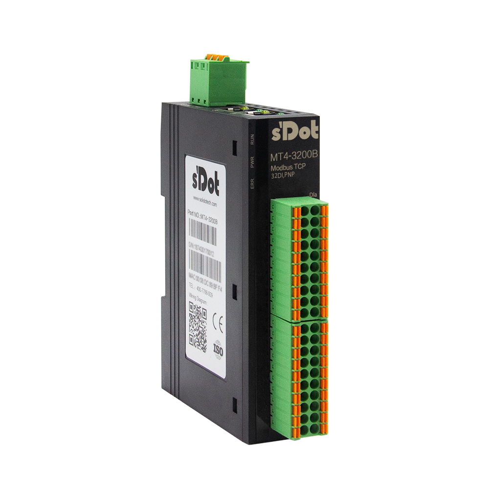
MT4-3200B · 32 DI PNP
Two terminal blocks with 20 terminals each: A = upper block, B = lower block. “B11” means block B, terminal 11.
All at once
| Task | from address | Count |
|---|---|---|
| Read all inputs | 100011000011x 11x 0 | 32 |
Digital inputs X00–X1F
| Terminal | Signal | Address (1x discrete input) |
|---|---|---|
| A1 | X00 | 100011000011x 11x 0 |
| A2 | X01 | 100021000021x 21x 1 |
| A3 | X02 | 100031000031x 31x 2 |
| A4 | X03 | 100041000041x 41x 3 |
| A5 | X04 | 100051000051x 51x 4 |
| A6 | X05 | 100061000061x 61x 5 |
| A7 | X06 | 100071000071x 71x 6 |
| A8 | X07 | 100081000081x 81x 7 |
| A11 | X08 | 100091000091x 91x 8 |
| A12 | X09 | 100101000101x 101x 9 |
| A13 | X0A | 100111000111x 111x 10 |
| A14 | X0B | 100121000121x 121x 11 |
| A15 | X0C | 100131000131x 131x 12 |
| A16 | X0D | 100141000141x 141x 13 |
| A17 | X0E | 100151000151x 151x 14 |
| A18 | X0F | 100161000161x 161x 15 |
| B1 | X10 | 100171000171x 171x 16 |
| B2 | X11 | 100181000181x 181x 17 |
| B3 | X12 | 100191000191x 191x 18 |
| B4 | X13 | 100201000201x 201x 19 |
| B5 | X14 | 100211000211x 211x 20 |
| B6 | X15 | 100221000221x 221x 21 |
| B7 | X16 | 100231000231x 231x 22 |
| B8 | X17 | 100241000241x 241x 23 |
| B11 | X18 | 100251000251x 251x 24 |
| B12 | X19 | 100261000261x 261x 25 |
| B13 | X1A | 100271000271x 271x 26 |
| B14 | X1B | 100281000281x 281x 27 |
| B15 | X1C | 100291000291x 291x 28 |
| B16 | X1D | 100301000301x 301x 29 |
| B17 | X1E | 100311000311x 311x 30 |
| B18 | X1F | 100321000321x 321x 31 |
Show wiring “PNP sensors on DI”
For specialists: function codes and protocol addresses
| Access | Function code | Protocol address (from 0) |
|---|---|---|
| Inputs individually or as a block | FC 02 | 0–31 |
| Read inputs via coils | FC 01 | 0–31 (0x ab 00001) |
| Inputs as a group of 16 | FC 03 | Registers 0–1 (4x from 40001), bit 0 = X00 |
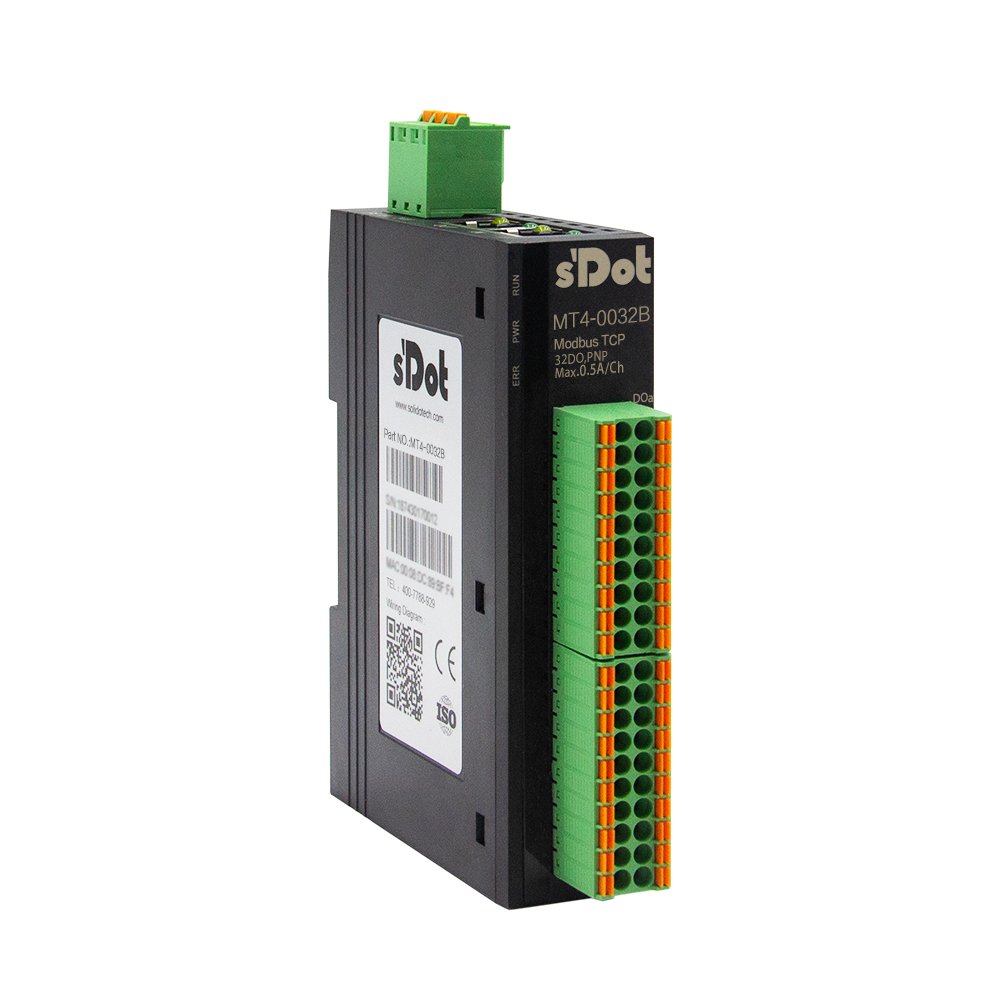
MT4-0032B · 32 DO PNP 0.5 A
Two terminal blocks with 20 terminals each: A = upper block, B = lower block. “B11” means block B, terminal 11.
All at once
| Task | from address | Count |
|---|---|---|
| Write all outputs | 000650000650x 650x 64 | 32 |
Digital outputs Y00–Y1F
| Terminal | Signal | Address (0x coil) |
|---|---|---|
| A1 | Y00 | 000650000650x 650x 64 |
| A2 | Y01 | 000660000660x 660x 65 |
| A3 | Y02 | 000670000670x 670x 66 |
| A4 | Y03 | 000680000680x 680x 67 |
| A5 | Y04 | 000690000690x 690x 68 |
| A6 | Y05 | 000700000700x 700x 69 |
| A7 | Y06 | 000710000710x 710x 70 |
| A8 | Y07 | 000720000720x 720x 71 |
| A11 | Y08 | 000730000730x 730x 72 |
| A12 | Y09 | 000740000740x 740x 73 |
| A13 | Y0A | 000750000750x 750x 74 |
| A14 | Y0B | 000760000760x 760x 75 |
| A15 | Y0C | 000770000770x 770x 76 |
| A16 | Y0D | 000780000780x 780x 77 |
| A17 | Y0E | 000790000790x 790x 78 |
| A18 | Y0F | 000800000800x 800x 79 |
| B1 | Y10 | 000810000810x 810x 80 |
| B2 | Y11 | 000820000820x 820x 81 |
| B3 | Y12 | 000830000830x 830x 82 |
| B4 | Y13 | 000840000840x 840x 83 |
| B5 | Y14 | 000850000850x 850x 84 |
| B6 | Y15 | 000860000860x 860x 85 |
| B7 | Y16 | 000870000870x 870x 86 |
| B8 | Y17 | 000880000880x 880x 87 |
| B11 | Y18 | 000890000890x 890x 88 |
| B12 | Y19 | 000900000900x 900x 89 |
| B13 | Y1A | 000910000910x 910x 90 |
| B14 | Y1B | 000920000920x 920x 91 |
| B15 | Y1C | 000930000930x 930x 92 |
| B16 | Y1D | 000940000940x 940x 93 |
| B17 | Y1E | 000950000950x 950x 94 |
| B18 | Y1F | 000960000960x 960x 95 |
Show wiring “Valve and lamp on DO”
For specialists: function codes and protocol addresses
| Access | Function code | Protocol address (from 0) |
|---|---|---|
| Write outputs | FC 15 | 64–95 |
| Read back outputs | FC 01 | 64–95 |
| Outputs as a group of 16 | FC 16 / FC 03 | Registers 4–5 (4x from 40005), bit 0 = Y00 |
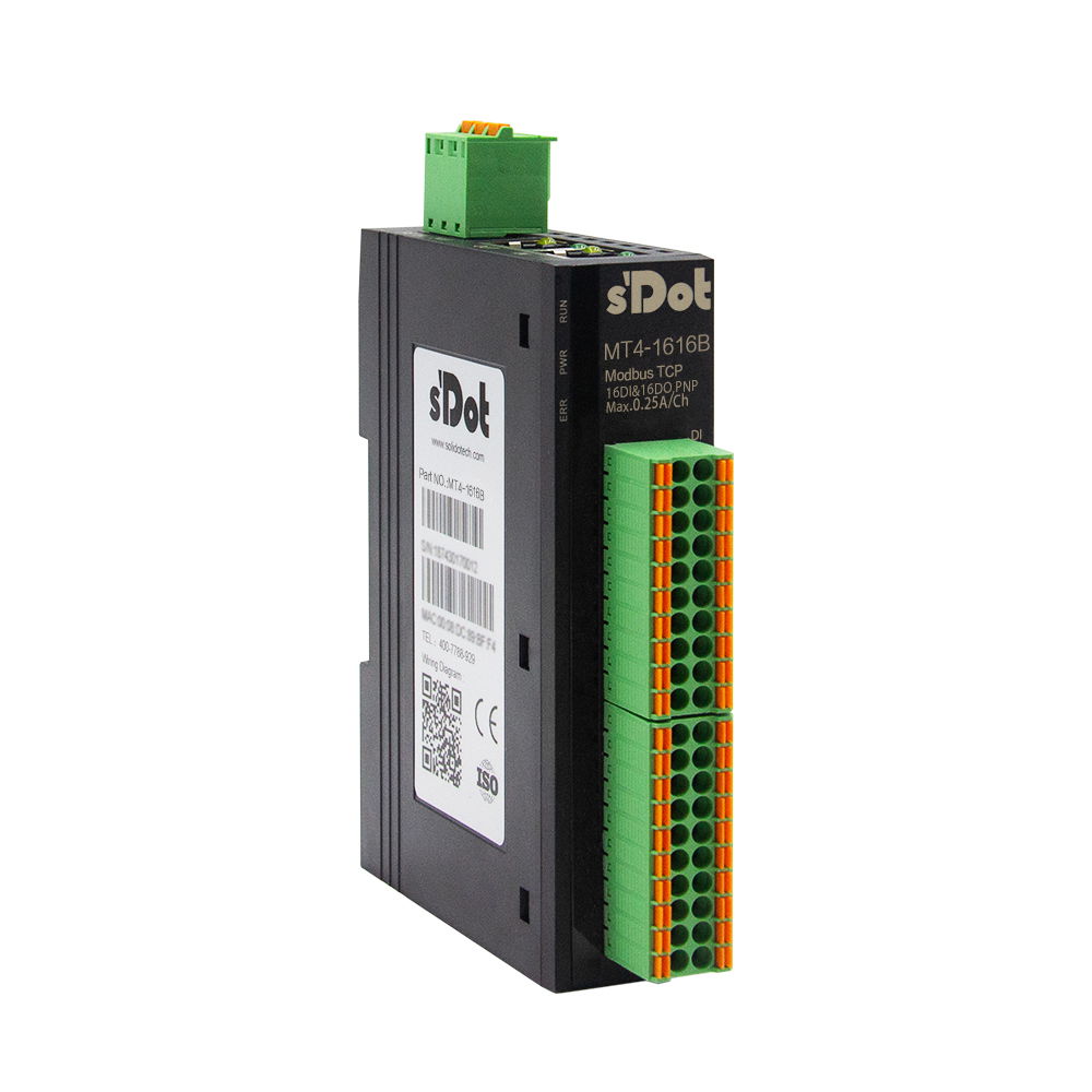
MT4-1616B · 16 DI / 16 DO PNP 0.5 A
Two terminal blocks with 20 terminals each: A = upper block, B = lower block. “B11” means block B, terminal 11.
All at once
| Task | from address | Count |
|---|---|---|
| Read all inputs | 100011000011x 11x 0 | 16 |
| Write all outputs | 000650000650x 650x 64 | 16 |
Digital inputs X00–X0F
| Terminal | Signal | Address (1x discrete input) |
|---|---|---|
| A1 | X00 | 100011000011x 11x 0 |
| A2 | X01 | 100021000021x 21x 1 |
| A3 | X02 | 100031000031x 31x 2 |
| A4 | X03 | 100041000041x 41x 3 |
| A5 | X04 | 100051000051x 51x 4 |
| A6 | X05 | 100061000061x 61x 5 |
| A7 | X06 | 100071000071x 71x 6 |
| A8 | X07 | 100081000081x 81x 7 |
| A11 | X08 | 100091000091x 91x 8 |
| A12 | X09 | 100101000101x 101x 9 |
| A13 | X0A | 100111000111x 111x 10 |
| A14 | X0B | 100121000121x 121x 11 |
| A15 | X0C | 100131000131x 131x 12 |
| A16 | X0D | 100141000141x 141x 13 |
| A17 | X0E | 100151000151x 151x 14 |
| A18 | X0F | 100161000161x 161x 15 |
Show wiring “PNP sensors on DI”
Digital outputs Y00–Y0F
| Terminal | Signal | Address (0x coil) |
|---|---|---|
| B1 | Y00 | 000650000650x 650x 64 |
| B2 | Y01 | 000660000660x 660x 65 |
| B3 | Y02 | 000670000670x 670x 66 |
| B4 | Y03 | 000680000680x 680x 67 |
| B5 | Y04 | 000690000690x 690x 68 |
| B6 | Y05 | 000700000700x 700x 69 |
| B7 | Y06 | 000710000710x 710x 70 |
| B8 | Y07 | 000720000720x 720x 71 |
| B11 | Y08 | 000730000730x 730x 72 |
| B12 | Y09 | 000740000740x 740x 73 |
| B13 | Y0A | 000750000750x 750x 74 |
| B14 | Y0B | 000760000760x 760x 75 |
| B15 | Y0C | 000770000770x 770x 76 |
| B16 | Y0D | 000780000780x 780x 77 |
| B17 | Y0E | 000790000790x 790x 78 |
| B18 | Y0F | 000800000800x 800x 79 |
Show wiring “Valve and lamp on DO”
For specialists: function codes and protocol addresses
| Access | Function code | Protocol address (from 0) |
|---|---|---|
| Inputs individually or as a block | FC 02 | 0–15 |
| Read inputs via coils | FC 01 | 0–15 (0x ab 00001) |
| Inputs as a group of 16 | FC 03 | Register 0 (4x from 40001), bit 0 = X00 |
| Write outputs | FC 15 | 64–79 |
| Read back outputs | FC 01 | 64–79 |
| Outputs as a group of 16 | FC 16 / FC 03 | Register 4 (4x from 40005), bit 0 = Y00 |
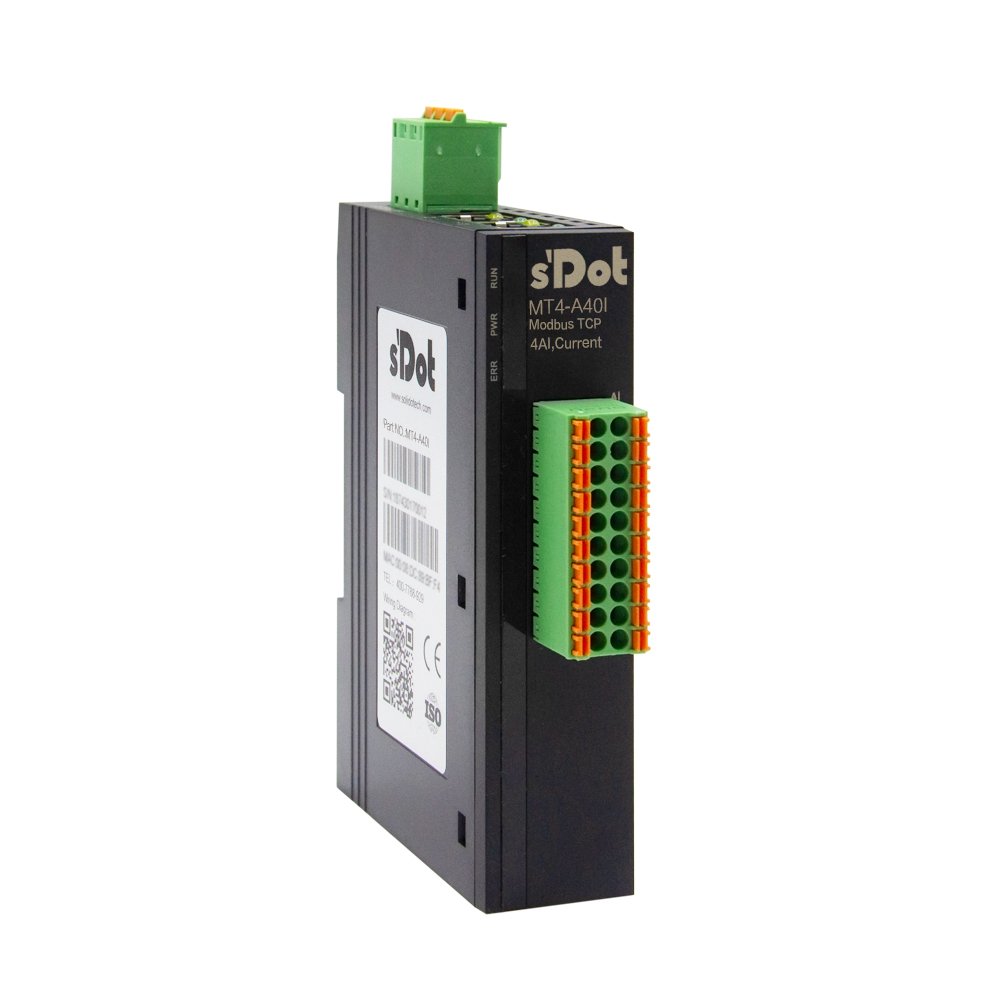
MT4-A40I · 4 AI 0/4–20 mA
All at once
| Task | from address | Count |
|---|---|---|
| Read all measured values | 400094000094x 94x 8 | 4 |
| Set measuring ranges | 400334000334x 334x 32 | 4 |
Analog inputs AI0–AI3
| Terminal | Signal | Measured value (4x, read) | Measuring range (4x, write) |
|---|---|---|---|
| 1 / 11 | AI0 / COM | 400094000094x 94x 8 | 400334000334x 334x 32 |
| 2 / 12 | AI1 / COM | 400104000104x 104x 9 | 400344000344x 344x 33 |
| 3 / 13 | AI2 / COM | 400114000114x 114x 10 | 400354000354x 354x 34 |
| 4 / 14 | AI3 / COM | 400124000124x 124x 11 | 400364000364x 364x 35 |
Show wiring “Transmitter 4-wire”Show wiring “3-wire transmitter”Show wiring “2-wire transmitter 4–20 mA”
For specialists: function codes and protocol addresses
| Access | Function code | Protocol address (from 0) |
|---|---|---|
| Read measured values | FC 03 | 8–11 |
| Write measuring ranges | FC 16 | 32–35 |
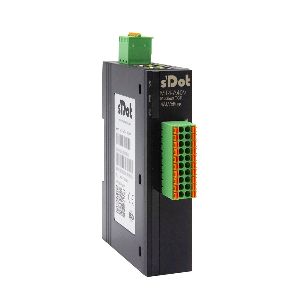
MT4-A40V · 4 AI ±10 V / 0–10 V
All at once
| Task | from address | Count |
|---|---|---|
| Read all measured values | 400094000094x 94x 8 | 4 |
| Set measuring ranges | 400334000334x 334x 32 | 4 |
Analog inputs AI0–AI3
| Terminal | Signal | Measured value (4x, read) | Measuring range (4x, write) |
|---|---|---|---|
| 1 / 11 | AI0 / COM | 400094000094x 94x 8 | 400334000334x 334x 32 |
| 2 / 12 | AI1 / COM | 400104000104x 104x 9 | 400344000344x 344x 33 |
| 3 / 13 | AI2 / COM | 400114000114x 114x 10 | 400354000354x 354x 34 |
| 4 / 14 | AI3 / COM | 400124000124x 124x 11 | 400364000364x 364x 35 |
Show wiring “Transmitter 4-wire”Show wiring “3-wire transmitter”
For specialists: function codes and protocol addresses
| Access | Function code | Protocol address (from 0) |
|---|---|---|
| Read measured values | FC 03 | 8–11 |
| Write measuring ranges | FC 16 | 32–35 |
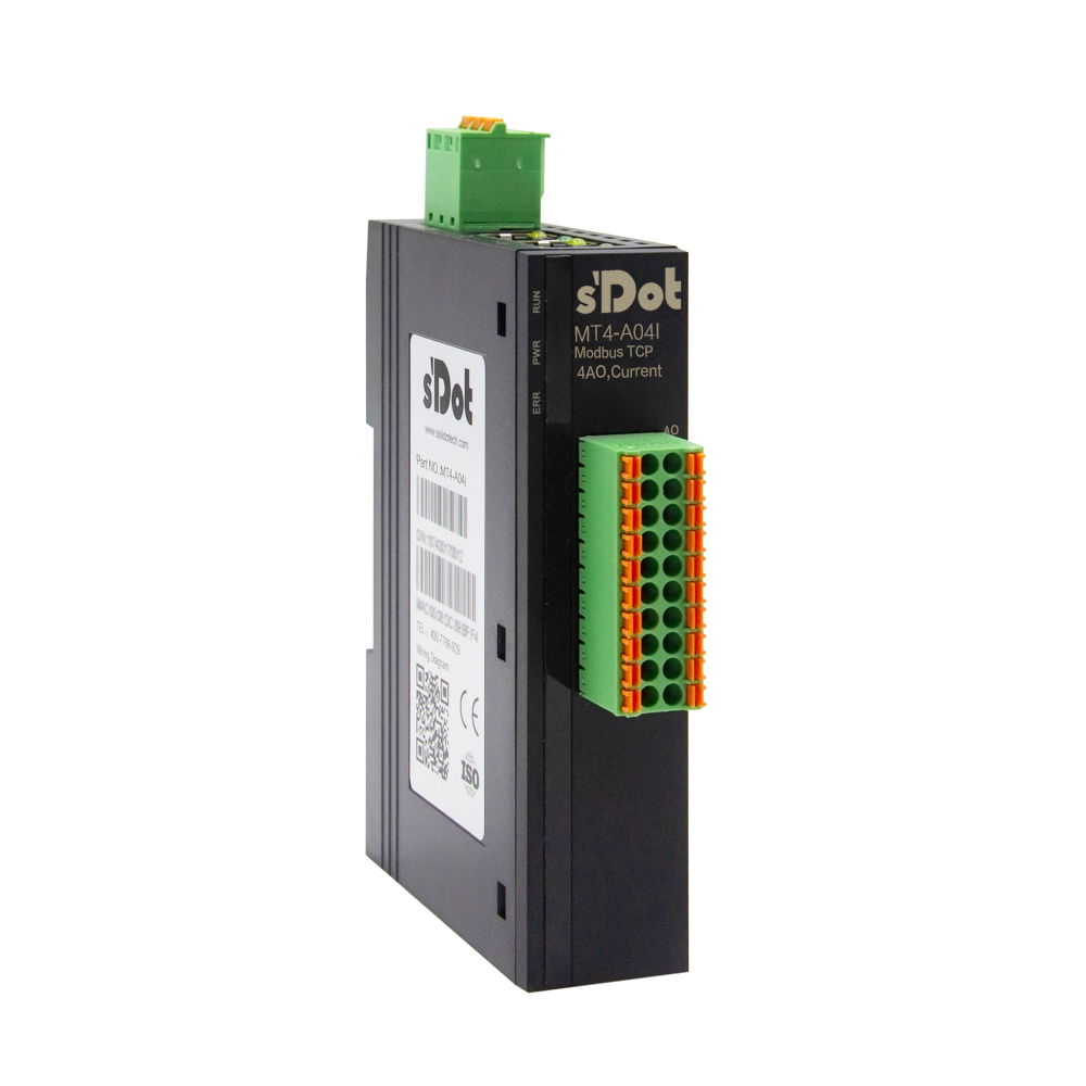
MT4-A04I · 4 AO 0/4–20 mA
All at once
| Task | from address | Count |
|---|---|---|
| Write all setpoints | 400174000174x 174x 16 | 4 |
| Set output ranges | 400334000334x 334x 32 | 4 |
Analog outputs AO0–AO3
| Terminal | Signal | Setpoint (4x, write) | Output range (4x, write) |
|---|---|---|---|
| 1 / 11 | AO0 / COM | 400174000174x 174x 16 | 400334000334x 334x 32 |
| 2 / 12 | AO1 / COM | 400184000184x 184x 17 | 400344000344x 344x 33 |
| 3 / 13 | AO2 / COM | 400194000194x 194x 18 | 400354000354x 354x 34 |
| 4 / 14 | AO3 / COM | 400204000204x 204x 19 | 400364000364x 364x 35 |
Show wiring “Setpoint to frequency inverter”
For specialists: function codes and protocol addresses
| Access | Function code | Protocol address (from 0) |
|---|---|---|
| Write setpoints | FC 16 | 16–19 |
| Write ranges | FC 16 | 32–35 |
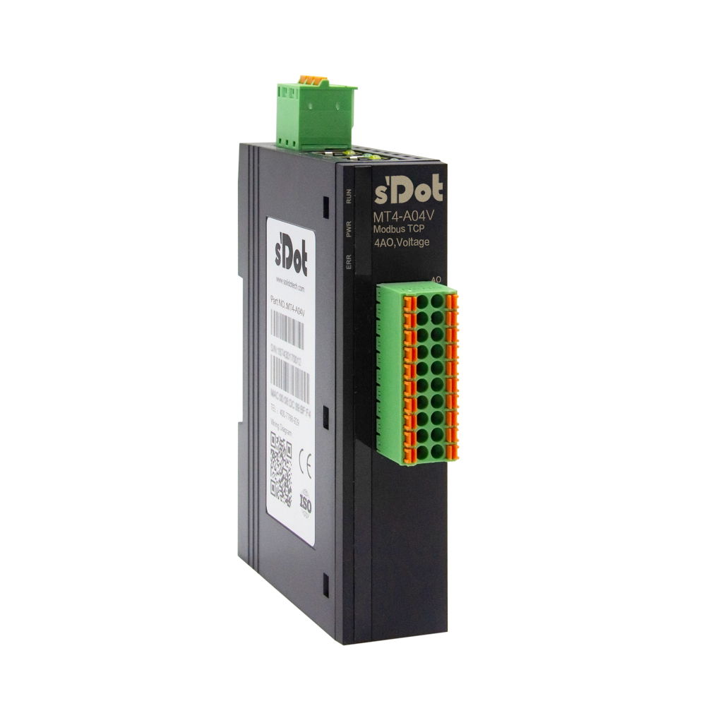
MT4-A04V · 4 AO ±10 V / 0–10 V
All at once
| Task | from address | Count |
|---|---|---|
| Write all setpoints | 400174000174x 174x 16 | 4 |
| Set output ranges | 400334000334x 334x 32 | 4 |
Analog outputs AO0–AO3
| Terminal | Signal | Setpoint (4x, write) | Output range (4x, write) |
|---|---|---|---|
| 1 / 11 | AO0 / COM | 400174000174x 174x 16 | 400334000334x 334x 32 |
| 2 / 12 | AO1 / COM | 400184000184x 184x 17 | 400344000344x 344x 33 |
| 3 / 13 | AO2 / COM | 400194000194x 194x 18 | 400354000354x 354x 34 |
| 4 / 14 | AO3 / COM | 400204000204x 204x 19 | 400364000364x 364x 35 |
Show wiring “Setpoint to frequency inverter”
For specialists: function codes and protocol addresses
| Access | Function code | Protocol address (from 0) |
|---|---|---|
| Write setpoints | FC 16 | 16–19 |
| Write ranges | FC 16 | 32–35 |
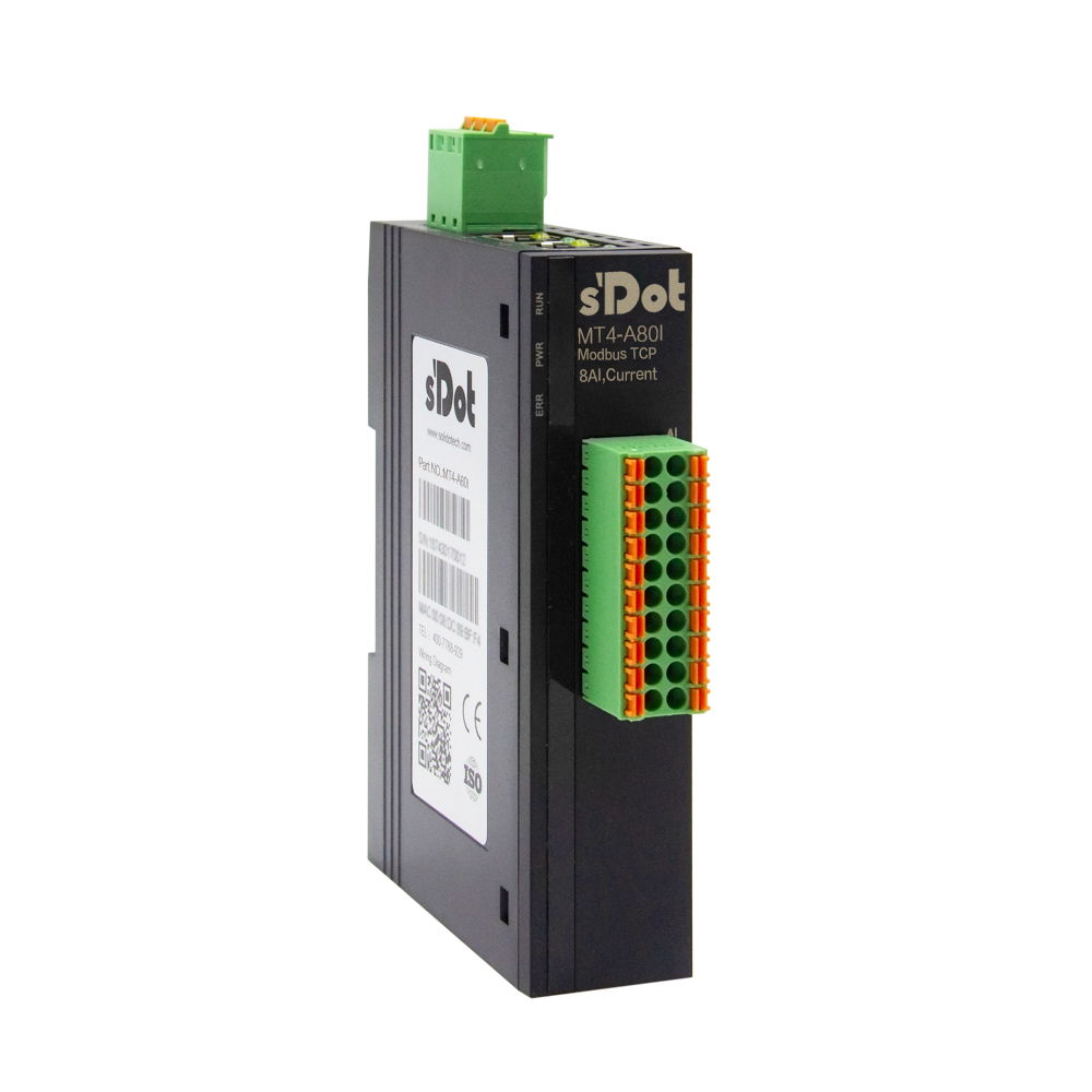
MT4-A80I · 8 AI 0/4–20 mA
All at once
| Task | from address | Count |
|---|---|---|
| Read all measured values | 400094000094x 94x 8 | 8 |
| Set measuring ranges | 400334000334x 334x 32 | 8 |
Analog inputs AI0–AI7
| Terminal | Signal | Measured value (4x, read) | Measuring range (4x, write) |
|---|---|---|---|
| 1 / 11 | AI0 / COM | 400094000094x 94x 8 | 400334000334x 334x 32 |
| 2 / 12 | AI1 / COM | 400104000104x 104x 9 | 400344000344x 344x 33 |
| 3 / 13 | AI2 / COM | 400114000114x 114x 10 | 400354000354x 354x 34 |
| 4 / 14 | AI3 / COM | 400124000124x 124x 11 | 400364000364x 364x 35 |
| 5 / 15 | AI4 / COM | 400134000134x 134x 12 | 400374000374x 374x 36 |
| 6 / 16 | AI5 / COM | 400144000144x 144x 13 | 400384000384x 384x 37 |
| 7 / 17 | AI6 / COM | 400154000154x 154x 14 | 400394000394x 394x 38 |
| 8 / 18 | AI7 / COM | 400164000164x 164x 15 | 400404000404x 404x 39 |
Show wiring “Transmitter 4-wire”Show wiring “3-wire transmitter”Show wiring “2-wire transmitter 4–20 mA”
For specialists: function codes and protocol addresses
| Access | Function code | Protocol address (from 0) |
|---|---|---|
| Read measured values | FC 03 | 8–15 |
| Write measuring ranges | FC 16 | 32–39 |
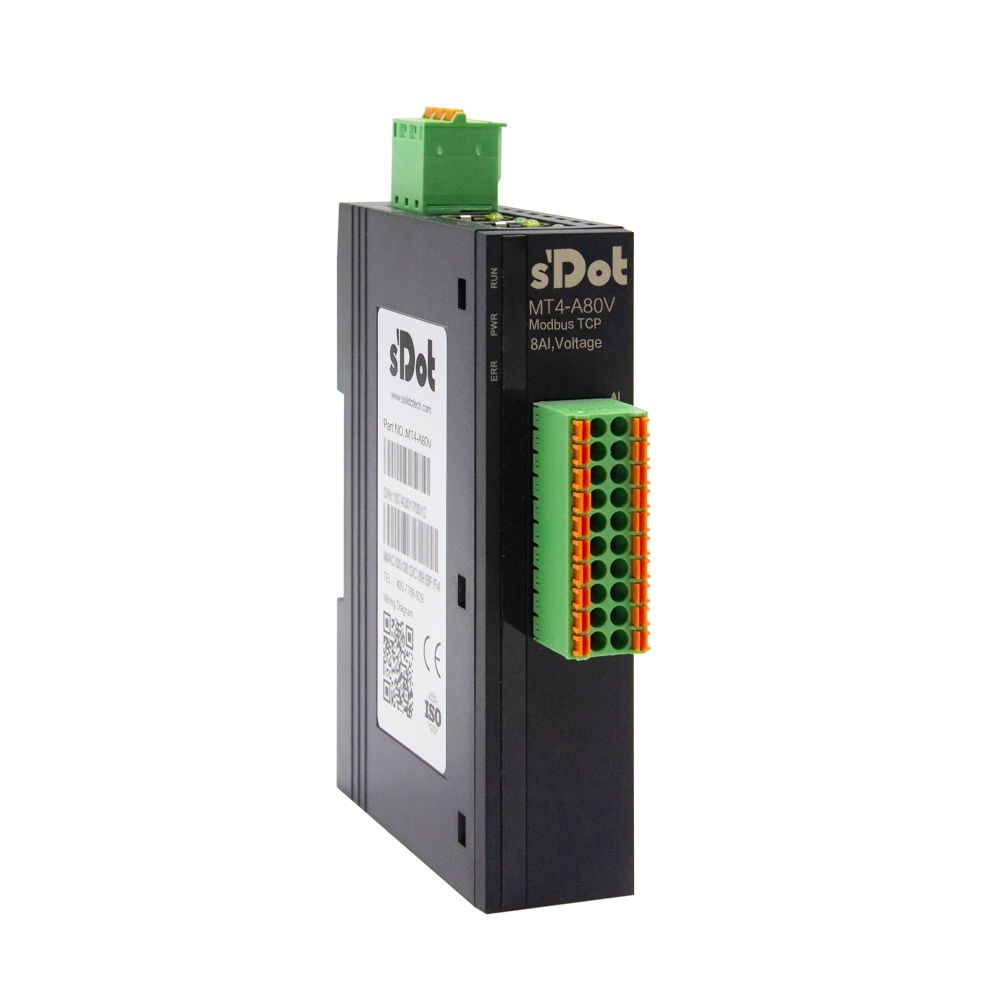
MT4-A80V · 8 AI ±10 V / 0–10 V
All at once
| Task | from address | Count |
|---|---|---|
| Read all measured values | 400094000094x 94x 8 | 8 |
| Set measuring ranges | 400334000334x 334x 32 | 8 |
Analog inputs AI0–AI7
| Terminal | Signal | Measured value (4x, read) | Measuring range (4x, write) |
|---|---|---|---|
| 1 / 11 | AI0 / COM | 400094000094x 94x 8 | 400334000334x 334x 32 |
| 2 / 12 | AI1 / COM | 400104000104x 104x 9 | 400344000344x 344x 33 |
| 3 / 13 | AI2 / COM | 400114000114x 114x 10 | 400354000354x 354x 34 |
| 4 / 14 | AI3 / COM | 400124000124x 124x 11 | 400364000364x 364x 35 |
| 5 / 15 | AI4 / COM | 400134000134x 134x 12 | 400374000374x 374x 36 |
| 6 / 16 | AI5 / COM | 400144000144x 144x 13 | 400384000384x 384x 37 |
| 7 / 17 | AI6 / COM | 400154000154x 154x 14 | 400394000394x 394x 38 |
| 8 / 18 | AI7 / COM | 400164000164x 164x 15 | 400404000404x 404x 39 |
Show wiring “Transmitter 4-wire”Show wiring “3-wire transmitter”
For specialists: function codes and protocol addresses
| Access | Function code | Protocol address (from 0) |
|---|---|---|
| Read measured values | FC 03 | 8–15 |
| Write measuring ranges | FC 16 | 32–39 |
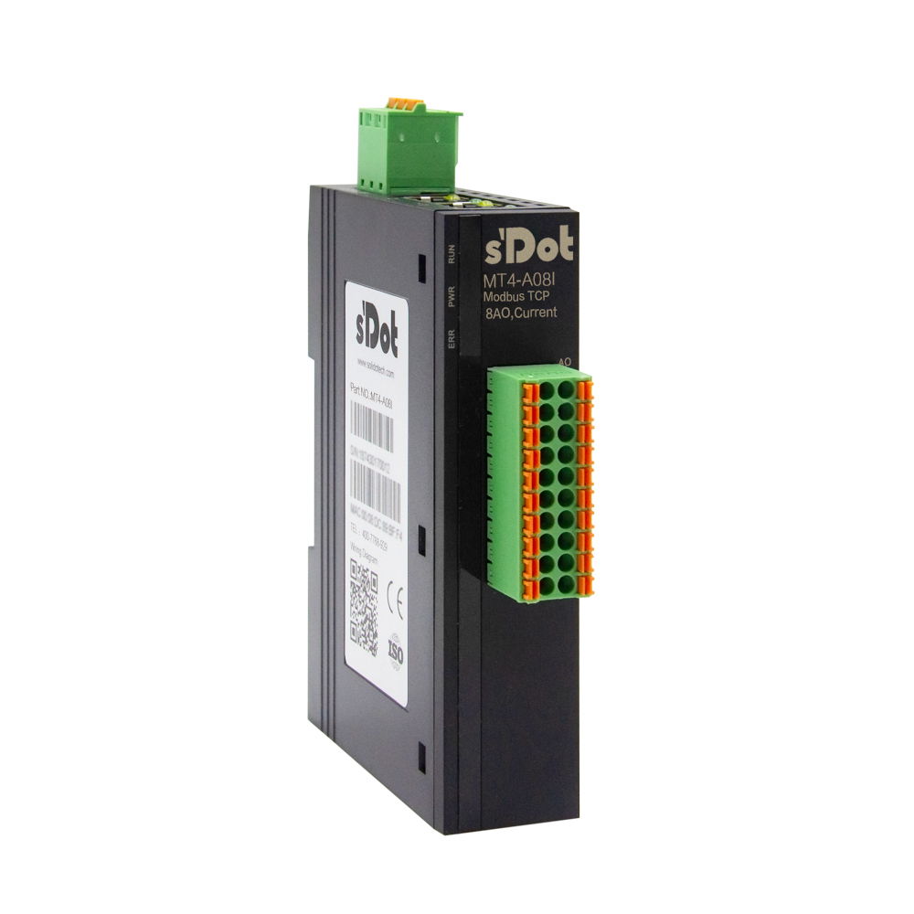
MT4-A08I · 8 AO 0/4–20 mA
All at once
| Task | from address | Count |
|---|---|---|
| Write all setpoints | 400174000174x 174x 16 | 8 |
| Set output ranges | 400334000334x 334x 32 | 8 |
Analog outputs AO0–AO7
| Terminal | Signal | Setpoint (4x, write) | Output range (4x, write) |
|---|---|---|---|
| 1 / 11 | AO0 / COM | 400174000174x 174x 16 | 400334000334x 334x 32 |
| 2 / 12 | AO1 / COM | 400184000184x 184x 17 | 400344000344x 344x 33 |
| 3 / 13 | AO2 / COM | 400194000194x 194x 18 | 400354000354x 354x 34 |
| 4 / 14 | AO3 / COM | 400204000204x 204x 19 | 400364000364x 364x 35 |
| 5 / 15 | AO4 / COM | 400214000214x 214x 20 | 400374000374x 374x 36 |
| 6 / 16 | AO5 / COM | 400224000224x 224x 21 | 400384000384x 384x 37 |
| 7 / 17 | AO6 / COM | 400234000234x 234x 22 | 400394000394x 394x 38 |
| 8 / 18 | AO7 / COM | 400244000244x 244x 23 | 400404000404x 404x 39 |
Show wiring “Setpoint to frequency inverter”
For specialists: function codes and protocol addresses
| Access | Function code | Protocol address (from 0) |
|---|---|---|
| Write setpoints | FC 16 | 16–23 |
| Write ranges | FC 16 | 32–39 |
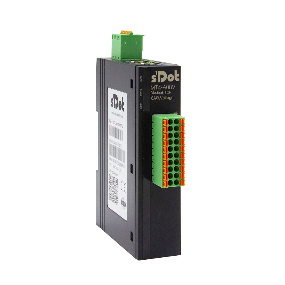
MT4-A08V · 8 AO ±10 V / 0–10 V
All at once
| Task | from address | Count |
|---|---|---|
| Write all setpoints | 400174000174x 174x 16 | 8 |
| Set output ranges | 400334000334x 334x 32 | 8 |
Analog outputs AO0–AO7
| Terminal | Signal | Setpoint (4x, write) | Output range (4x, write) |
|---|---|---|---|
| 1 / 11 | AO0 / COM | 400174000174x 174x 16 | 400334000334x 334x 32 |
| 2 / 12 | AO1 / COM | 400184000184x 184x 17 | 400344000344x 344x 33 |
| 3 / 13 | AO2 / COM | 400194000194x 194x 18 | 400354000354x 354x 34 |
| 4 / 14 | AO3 / COM | 400204000204x 204x 19 | 400364000364x 364x 35 |
| 5 / 15 | AO4 / COM | 400214000214x 214x 20 | 400374000374x 374x 36 |
| 6 / 16 | AO5 / COM | 400224000224x 224x 21 | 400384000384x 384x 37 |
| 7 / 17 | AO6 / COM | 400234000234x 234x 22 | 400394000394x 394x 38 |
| 8 / 18 | AO7 / COM | 400244000244x 244x 23 | 400404000404x 404x 39 |
Show wiring “Setpoint to frequency inverter”
For specialists: function codes and protocol addresses
| Access | Function code | Protocol address (from 0) |
|---|---|---|
| Write setpoints | FC 16 | 16–23 |
| Write ranges | FC 16 | 32–39 |
MT4-88B40I · 8 DI / 8 DO PNP, 4 AI 0/4–20 mA
Two terminal blocks with 20 terminals each: A = upper block, B = lower block. “B11” means block B, terminal 11.
All at once
| Task | from address | Count |
|---|---|---|
| Read all inputs | 100011000011x 11x 0 | 8 |
| Write all outputs | 000650000650x 650x 64 | 8 |
| Read all measured values | 400094000094x 94x 8 | 4 |
| Set measuring ranges | 400334000334x 334x 32 | 4 |
Digital inputs X00–X07
| Terminal | Signal | Address (1x discrete input) |
|---|---|---|
| B1 | X00 | 100011000011x 11x 0 |
| B2 | X01 | 100021000021x 21x 1 |
| B3 | X02 | 100031000031x 31x 2 |
| B4 | X03 | 100041000041x 41x 3 |
| B5 | X04 | 100051000051x 51x 4 |
| B6 | X05 | 100061000061x 61x 5 |
| B7 | X06 | 100071000071x 71x 6 |
| B8 | X07 | 100081000081x 81x 7 |
Show wiring “PNP sensors on DI”
Digital outputs Y00–Y07
| Terminal | Signal | Address (0x coil) |
|---|---|---|
| B11 | Y00 | 000650000650x 650x 64 |
| B12 | Y01 | 000660000660x 660x 65 |
| B13 | Y02 | 000670000670x 670x 66 |
| B14 | Y03 | 000680000680x 680x 67 |
| B15 | Y04 | 000690000690x 690x 68 |
| B16 | Y05 | 000700000700x 700x 69 |
| B17 | Y06 | 000710000710x 710x 70 |
| B18 | Y07 | 000720000720x 720x 71 |
Show wiring “Valve and lamp on DO”
Analog inputs AI0–AI3
| Terminal | Signal | Measured value (4x, read) | Measuring range (4x, write) |
|---|---|---|---|
| A1 / A11 | AI0 / COM | 400094000094x 94x 8 | 400334000334x 334x 32 |
| A2 / A12 | AI1 / COM | 400104000104x 104x 9 | 400344000344x 344x 33 |
| A3 / A13 | AI2 / COM | 400114000114x 114x 10 | 400354000354x 354x 34 |
| A4 / A14 | AI3 / COM | 400124000124x 124x 11 | 400364000364x 364x 35 |
Show wiring “Transmitter 4-wire”Show wiring “3-wire transmitter”Show wiring “2-wire transmitter 4–20 mA”
For specialists: function codes and protocol addresses
| Access | Function code | Protocol address (from 0) |
|---|---|---|
| Inputs individually or as a block | FC 02 | 0–7 |
| Read inputs via coils | FC 01 | 0–7 (0x ab 00001) |
| Inputs as a group of 16 | FC 03 | Register 0 (4x from 40001), bit 0 = X00 |
| Write outputs | FC 15 | 64–71 |
| Read back outputs | FC 01 | 64–71 |
| Outputs as a group of 16 | FC 16 / FC 03 | Register 4 (4x from 40005), bit 0 = Y00 |
| Read measured values | FC 03 | 8–11 |
| Write measuring ranges | FC 16 | 32–35 |
Range codes of the analog channels
| Code | Current (MT4-…I) | Voltage (MT4-…V) |
|---|---|---|
| 0 | 4–20 mA → 0–65535 | ±10 V → −32768–32767 |
| 1 | 0–20 mA → 0–65535 | 0–10 V → 0–65535 |
| 2 | 4–20 mA → 0–27648 | ±10 V → −27648–27648 |
| 3 | 0–20 mA → 0–27648 | ±5 V → −27648–27648 |
| 4 | – | 1–5 V → 0–27648 |
| 5 | – | 2–10 V → 0–27648 |
How Modbus addresses work
Modbus divides the data into four areas. Your software usually wants the area first and then the number. Some programs write both together: the first digit is the area, the rest is the number – so 40009 means area 4x, number 9.
The Modbus standard counts from 1: the first holding register is called 40001, and the request frame carries address 0 for it. Some programs count from 0 and show the same register as 40000 or number 0. The 6-digit notation (400001) is used by programs that can address more than 9999 addresses per area.
| Range | Name | Content | on the MT4 |
|---|---|---|---|
| 0x | Coils | Bits, read and write | Outputs Y (from number 65), inputs also readable from number 1 |
| 1x | Discrete inputs | Bits, read only | Inputs X (from number 1) |
| 3x | Input registers | 16-bit values, read only | not used |
| 4x | Holding registers | 16-bit values, read and write | Analog values, measuring ranges; inputs and outputs also as a group of 16 |
Not sure whether your software counts from 0 or from 1? Set X00 to “1” and read the address from the table. If the neighbouring channel X01 responds instead, or nothing at all, switch the counting mode or use the address one below.
For specialists: function codes and protocol addresses
According to the manual, the MT4 supports five function codes: 01 read coils, 02 read discrete inputs, 03 read holding registers, 15 write multiple coils and 16 write multiple registers (ch. 7.4).
The manual does not list FC 04 (input registers), FC 05 (write single coil) or FC 06 (write single register). In your master, set outputs and registers to “Write Multiple” (FC 15/16), even if you only write one value.
Protocol addresses from 0, as they appear in the request frame.
- The assignment X00 = first input (10001) and Y00 = coil 00065 (protocol address 64) is derived from the address table in the manual: channels 0–63 are inputs, outputs start at channel 64. Bit 0 of a register = lowest channel is assumed; the manual does not state the bit order.
- Out of the box, switching off the outputs on connection loss is disabled (shutdown time 0). How to have them switched off after 1–30 s is described in “First steps”, step “Outputs on loss of connection”.
Source: MT4 Series Integrated I/O User Manual V1.16 (12/2025), ch. 7.1–7.5; MT4-88B40I user manual ch. 6.
First steps with the Solidot MT4
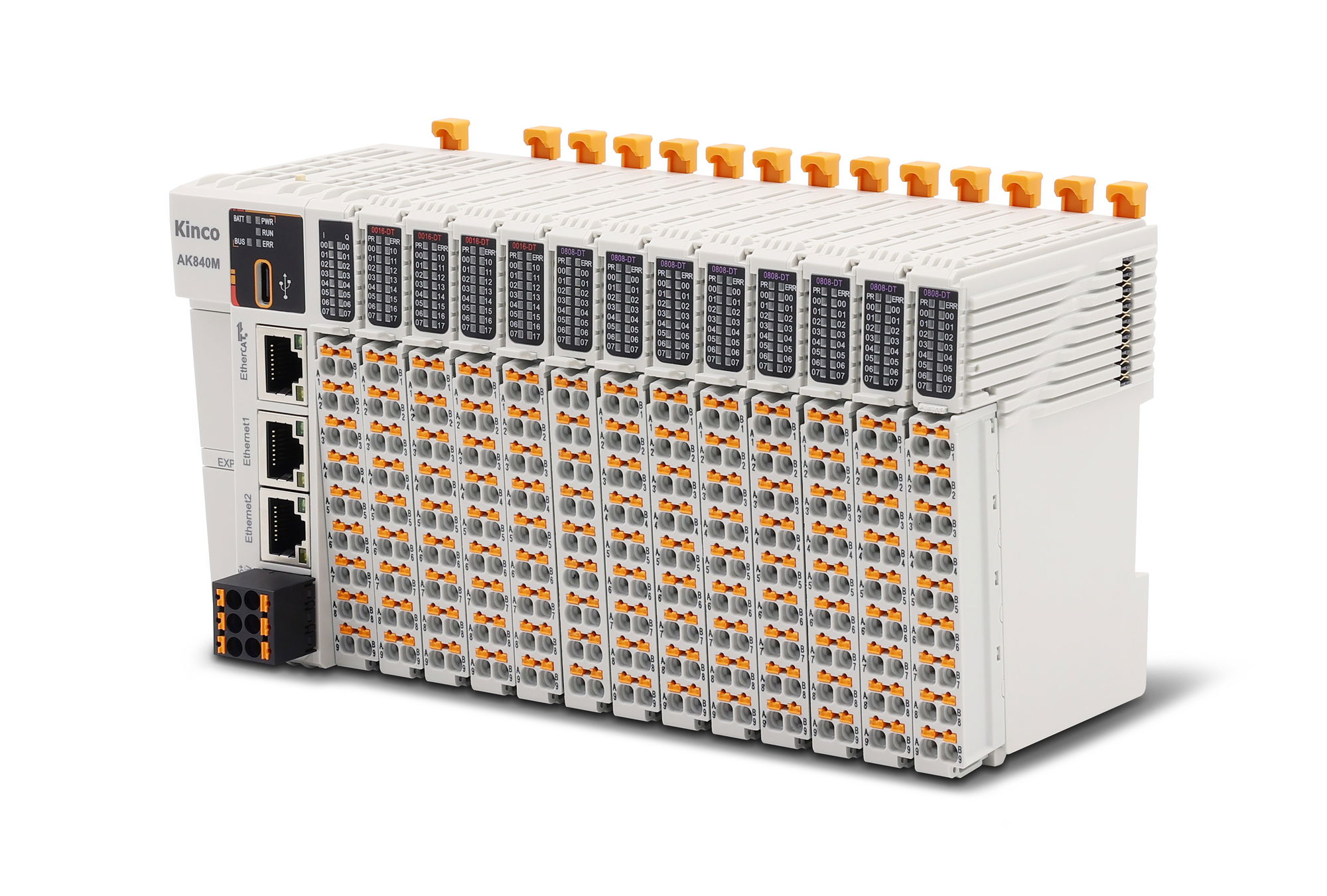
The MT4 brings inputs and outputs straight onto Ethernet: Modbus TCP, two RJ45 sockets with a built-in switch, spring-cage terminals. This guide applies to all MT4 models in the Shop – digital with 16 or 32 channels, analog with four or eight channels, and the mixed MT4-88B40I. It takes you from snapping the module onto the DIN rail to the first signal in your controller: power supply, wiring, setting the IP address, creating the registers in the master.
Mount and remove only with the power off (manual chap. 5).
The module has protection class IP20 and belongs in a control cabinet or an enclosure.
Set up the system supply (module electronics) and the field supply (inputs and outputs) separately and do not mix them.
Ground PE at the supply terminal securely.
All modules ship with the same IP address 192.168.1.120. Do not plug several new modules into the same network at once; change their addresses one after the other.
1Mount on the DIN railRequired
The module measures 25 × 102 × 72 mm (W × H × D) and snaps onto a 35 mm DIN rail. It must sit vertically so that air can flow through the housing.
Minimum clearances according to the manual: 10 mm to neighbouring modules, 45 mm above and 25 mm below to other devices or cable ducts. Do not mount next to or above devices that give off a lot of heat.
Mounting
Pull the latch at the bottom of the module outwards until it audibly clicks into place.
Hook the top edge of the mounting clip onto the top edge of the DIN rail and swing the module onto the rail.
Push the latch towards the rail until it clicks – the module is now secure.
Removal: insert a flat-blade screwdriver into the latch, lever it towards the module (it clicks) and remove the module in reverse order.
Source: Manual chap. 1.2, 3.1, 5, 5.1, 5.2
2Connect system and field supplyRequired
The system supply powers the electronics: 24 V DC (18–30 V) to the three-pole terminal on the top, assigned 24V, 0V and PE. The manual recommends a twisted cable.
The field supply powers the inputs and outputs and goes to terminals 24V/0V in the terminal block (terminal 9/10 and 19/20, each pair connected internally). Modules with two blocks (32 channels, 16 DI/16 DO) need it on both blocks, because the blocks are not connected internally. Loads on outputs run from the same field supply as their block.
Analog inputs and voltage outputs have no field terminals. The current outputs (MT4-A04I, MT4-A08I) need 24 V at terminal 9/10 or 19/20.
Terminals
Terminal Cross-section Note Supply, 3-pole 0.3–1.5 mm² (22–16 AWG) 24V, 0V, PE Signal terminals, 2 × 20-pole 0.3–1.0 mm² (22–17 AWG) Spring-cage, screwless The manual does not state the current consumption of the electronics or the permissible current per field terminal. The cross-sections in the wiring diagram are derived from this and marked as such.
After switching on, PWR lights up green.
Show wiring “System supply 24 V”Show wiring “Field supply 24 V”
Source: Manual chap. 3.1, 6.1, 6.2, wiring diagrams chap. 6.3; MT4-88B40I chap. 5.3
3Wire inputs and outputsRequired
Strip 10 mm of insulation. Insert solid wires directly; use a wire ferrule for fine-stranded wires (length 10 mm, e.g. E0510 for 0.5 mm²). Press the button above the terminal with a flat-blade screwdriver up to 3 mm wide.
Digital inputs are PNP: the sensor applies +24 V to the input (“1” from 15 V). Digital outputs are PNP with max. 500 mA per channel and switch +24 V to the load.
Each analog channel has one signal connection (AI0 … or AO0 …, terminal 1–8) and COM next to it (terminal 11–18). All COM are connected internally; all channels must be referenced to the same source. Use twisted, shielded pairs for analog signals.
Connecting analog transmitters (wiring diagrams chap. 6.3)
Type Signal to COM to 4-wire, own supply Signal + to AI Signal − 3-wire Signal output to AI 0 V of transmitter and power supply 2-wire 4–20 mA Loop (−) to AI, + to +24 V 0 V of the power supply On the current module, 2 V drop across the input at 20 mA (100 Ω, calculated). A 2-wire transmitter needs this voltage in addition to its minimum voltage.
Each channel has a green LED: it lights up as long as a signal is present at or output by the channel.
Show wiring “PNP sensors on DI”Show wiring “Valve and lamp on DO”Show wiring “Transmitter 4-wire”Show wiring “3-wire transmitter”Show wiring “2-wire transmitter 4–20 mA”Show wiring “Setpoint to frequency inverter”
Source: Manual chap. 3.2, 3.3, 4.2, 6.1, 6.2, 6.3
4Connect the PC and check the connectionRequired
From the factory, every module has the IP address 192.168.1.120, mask 255.255.255.0, gateway 192.168.1.1. For your PC to reach it, set the network adapter to a free address in the same network, e.g. 192.168.1.10.
Check the connection
Connect the PC to one of the two RJ45 sockets with a patch cable.
On the PC, set the address 192.168.1.10 and the mask 255.255.255.0 (example, the address is freely chosen).
Open the command prompt and enter ping 192.168.1.120.
Replies without packet loss: the connection is up. Otherwise check the cable, the addresses and the LEDs at the socket (green = link, orange flashing = data traffic).
Factory IP and addresses in the Modbus & IP tab
Source: Manual chap. 4.2, 7.1
5Set the IP addressRequired
Each module needs its own address in your plant network. You set it on the module's web page.
Assign a new address
Open http://192.168.1.120 in the browser.
Enter the new IP address, subnet mask and gateway.
Click Save and restart the module.
Switch the PC to the new network and check the new address with ping.
Connect the next module and change it the same way.
Write the new address on the module, e.g. with a label. If it is forgotten, the factory default helps (step “Troubleshooting and reset”).
Factory IP and addresses in the Modbus & IP tab
Source: Manual chap. 7.1
6Set up in the Modbus TCP masterRequired
The MT4 is a Modbus TCP slave. In your controller (PLC, HMI or PC), set it up with its IP address, port 502 and unit ID 1 (values from the CODESYS example in the manual). Function codes 1, 2, 3, 15 and 16 are supported.
Each channel has a fixed address. Which notation your software expects – 40001, 400001 or area + number such as 4x 1 with Kinco – you select in the Modbus & IP tab; it lists all channels of your model.
All channel addresses for your model, terminal by terminal, are in the Modbus & IP tab.
Address areas (counting from 1, Modbus standard)
Data Range Addresses Function code Digital inputs X00 … 1x Discrete Inputs ab 10001 02 Digital outputs Y00 … 0x Coils ab 00065 15, read back 01 Analog inputs AI0 … 4x Holding Register ab 40009 03 Analog outputs AO0 … 4x Holding Register ab 40017 16 Measuring range per channel 4x Holding Register ab 40033 16 If your software counts from 0, each address is one lower (40008 instead of 40009). Some programs use six digits: 400009.
The MT4 only knows function codes 01, 02, 03, 15 and 16. For single outputs, select “Write Multiple” (FC 15/16) in the master.
The assignment X00 = first input and Y00 = coil 65 (protocol address 64) is derived from the address table in the manual.
Show wiring “Modbus TCP to the master”
Source: Manual chap. 7.4, 7.5; MT4-88B40I chap. 6.4
7Example: CODESYS V3.5Optional
The manual shows the integration into CODESYS V3.5 step by step. Here it is in short form.
Set up the MT4 in CODESYS
Create a new project. Under “Device”, add an Ethernet adapter with Add Device and select the network adapter in the same network as the module.
Under the Ethernet adapter, add a “Modbus TCP Master”, and below it a “Modbus TCP Slave”.
In the slave under “General”, enter the IP address of the module, unit ID 1, response timeout 1000 ms and port 502.
Under “Modbus Slave Channel”, create the channels with “Add Channel”, e.g. function code 3, offset 0 for the inputs and function code 15, offset 64, length 16 for the outputs.
Analog inputs: function code 3, offset 8, length 8; plus function code 16, offset 32, length 8 for the measuring ranges.
Log in, start and watch or write the values under “ModbusTCPSlave I/O Mapping”.
Source: Manual chap. 7.5
8Select the measuring range of the analog channelsOptional
Each analog channel has its own measuring range. You set it via a register (32 + channel, function code 16) or on the module's web page. The code also determines which number range appears in the measured value register.
Range codes
Code Current (…I) Voltage (…V) 0 4–20 mA → 0–65535 ±10 V → −32768–32767 1 0–20 mA → 0–65535 0–10 V → 0–65535 2 4–20 mA → 0–27648 ±10 V → −27648–27648 3 0–20 mA → 0–27648 ±5 V → −27648–27648 4 – 1–5 V → 0–27648 5 – 2–10 V → 0–27648 Example (calculated, linear): code 2, transmitter 4–20 mA, 12 mA at the input → 13824 in the register (middle of 0–27648).
Codes 2 to 5 use the range 0–27648, which many controllers know as the nominal analog range. The manual does not state the factory default – so always set the range explicitly.
Resolution 16 bit, accuracy ±0.1 %, sampling up to 1 kS/s.
Show wiring “Transmitter 4-wire”Show wiring “Setpoint to frequency inverter”
Source: Manual chap. 2.2, 3.3, 7.3.2, 7.4
9Outputs on loss of connectionRequired
If the connection to the master is lost, the Clear/Keep setting on the web page determines what happens to the outputs. From the factory, the switch-off time is 0, so the function is off.
For valves, drives and anything that must not keep running uncontrolled: enter Clear/Keep = 0 and a switch-off time of 1–30 s. The module then switches the outputs off after this time. With Clear/Keep = 1, the outputs hold their last state.
Parameter Value Meaning Clear/Keep 0 Switch outputs off after the time has elapsed (factory default) Clear/Keep 1 Outputs hold the state before the loss of connection Switch-off time 1–30 s 0 = function off (factory default) Applies to all modules with outputs, digital and analog. The manual describes the setting in Internet Explorer; a current browser shows the same web page.
Show wiring “Valve and lamp on DO”
Source: Manual chap. 7.3.1; MT4-88B40I chap. 6.3.1
10Connect further modules in a lineOptional
Thanks to the built-in switch, you connect several MT4 without an external switch: ETH2 of one module to ETH1 of the next. Up to 127 stations are possible, max. 100 m per segment.
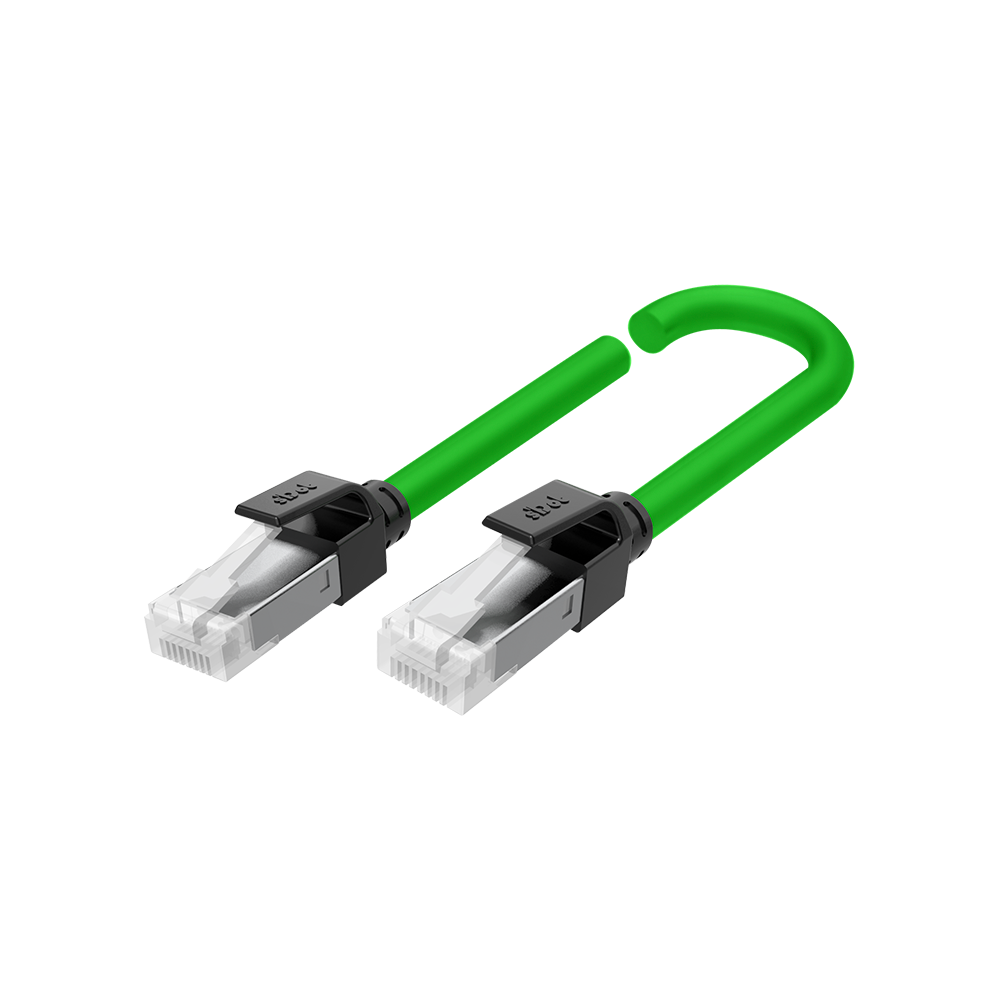
Patch cable category 5 or higher, double shielded (braid and foil), is recommended.
Each module in the line needs its own IP address (step “Set the IP address”).
If a module in the line has no power, you can no longer reach the modules behind it (derived from the built-in switch; the manual does not mention a bypass).
Show wiring “Further module in daisy chain”
Solidot patch cable 0.5 mSolidot patch cable 1 m
Source: Manual chap. 1.1, 3.1, 6.2
11Troubleshooting and resetRequired
Restore the factory IP
Leave the module switched on.
Press the reset button for 1 s, using an insulated tool less than 1.2 mm in diameter or thickness.
RUN/ERR flash and then light up steadily.
Switch the module off and on again. It can now be reached again at 192.168.1.120.
LEDs
LED State Meaning PWR (green) off no supply or faulty supply RUN (green) off Operating fault, e.g. communication timeout ERR (red) flashing Module fault, e.g. setting out of range or communication error Socket 1/2 green off no network connection Socket 1/2 orange off no data exchange Channel 0–F (green) off no signal at the channel or signal faulty Resetting restores the IP settings to factory default (192.168.1.120, mask 255.255.255.0, gateway 192.168.1.1).
Source: Manual chap. 4.2, 7.2
Revision 1.0 · 01.10.2026 · Source: MT4 Series Integrated I/O User Manual V1.16 (12/2025); MT4-88B40I user manual (2025). The manufacturer manual and applicable standards take precedence; installation and commissioning by a qualified electrician only.
Dimensions and mounting
All MT4 models are the same size and sit vertically on a 35 mm DIN rail. The drawing is projected from Solidot's 3D models.
Connectors and wires
Supply 24V · 0V · PE (top)
- Type
- 3-pin, spring-clamp
- Pitch
- 5.08 mm*
- Size
- approx. 9 × 19 mm, 17 mm above the housing*
- Cross-section
- 0.3–1.5 mm² (22–16 AWG)
- Strip length
- 10 mm
Signals (front)
- Type
- 20-pin, two rows of 10 terminals, spring-clamp with push button; one block (16 channels, analog) or two blocks (32 channels, 16/16, 88B40I)
- Pitch
- 3.5 mm*
- Size
- approx. 13 × 36 mm per block, 16 mm in front of the housing*
- Cross-section
- 0.3–1.0 mm² (22–17 AWG)
- Strip length
- 10 mm
Ethernet ETH1/ETH2 (top)
- Type
- 2 × RJ45 for patch cables Cat. 5 or higher, shielded (STP), max. 100 m
* measured from Solidot's 3D model, not in the manual. We measured the supply connector at ≈ 5.1 mm and assume the standard pitch of 5.08 mm.
Wire ferrules with plastic collar, sleeve length 10 mm: E0310 (0.3 mm²), E0510 (0.5), E7510 (0.75), E1010 (1.0), E1510 (1.5 mm², supply only). Solid wires without ferrule.
Tools: flat-blade screwdriver up to 3 mm to open the spring clamp; for the reset button an insulated tool thinner than 1.2 mm.
Cross-sections, ferrules and strip length: manual ch. 6.1 and 6.2.
Mounting step by step
1Choose the installation site
Protection class IP20: the module belongs in a control cabinet or an enclosure. The cabinet needs good ventilation, e.g. a fan.
Mount the module vertically so that air flows through the housing. Do not mount it next to or above devices that give off a lot of heat. Operating temperature 0–55 °C, humidity up to 95 %, non-condensing.
At least 10 mm to neighbouring modules, 45 mm upwards and 25 mm downwards to devices or cable ducts. This leaves room at the top for the supply connector and patch cables.
2Mounting and removing
Mount and remove only with the power off.
Pull the latch at the bottom of the module outwards until it clicks into place.
Hook the module onto the top of the DIN rail and swing it onto the rail.
Push the latch towards the rail until it clicks.
Removing: insert a flat-blade screwdriver into the latch, lever it towards the module and swing the module off.
3Connecting the wires
Strip 10 mm of the wire. Stranded wires get a wire ferrule with a 10 mm sleeve length; solid wires go in directly.
Press down the push button above the terminal with a flat-blade screwdriver (up to 3 mm), insert the wire, release, give the wire a short pull.
Signal terminals take 0.3–1.0 mm², the supply terminal 0.3–1.5 mm². Run the supply cable twisted, use shielded pairs for analog signals.
Show wiring “System supply 24 V”Show wiring “PNP sensors on DI”
Revision 2.0 · 01.10.2026 · Source: MT4 Series Integrated I/O User Manual V1.16 (12/2025), ch. 5; Solidot 3D models EC4_PN4_MT4_1/_2 V1.00. The manufacturer manual and applicable standards take precedence; installation by a qualified electrician only.
Stuck?
Our support helps you free of charge. Tell us what you are planning and which model you use – via the contact form, by email or in the community forum.
Contact formEmail support@spstiger.deAsk in the community forum
More ways to contact us: Support contacts
We have compiled and checked this page carefully from the manufacturer’s documentation. Even so, an error may have slipped in. The manufacturer’s manual and the applicable standards always take precedence. Spotted something? Let us know – we’ll be glad to fix it.
Downloads
User manual, MT4-88B40I manual (German), 2D and 3D drawings and EPLAN macros:
Solidot MT4 remote I/O
Accessories