



Frequency inverter · Quick Start Guide
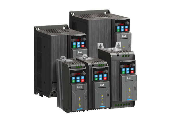
Multi-speed operation INVT GD28
Call up fixed speeds via switches or a PLC, without a potentiometer or analog signal: you store up to 16 steps in the drive and select them via digital inputs. Ideal for conveyors, pumps and fans with fixed operating points.
Disconnect all supplies and wait at least 5 minutes (manual, all GD28 models). Only then open the cover and touch the terminals.
The digital inputs work with 10–30 V DC (high level). Never apply mains voltage to the control terminals.
STO is bridged at the factory and therefore inactive. Using STO as a safety function requires a risk assessment and acceptance test.
1Set the frequency source to multi-step speedRequired
The drive separates two questions: where does the run command come from (P00.01), and where does the frequency come from (P00.06)? For multi-speed operation you change the frequency source. Digital inputs then select one of the stored steps.
If switches or a PLC are to start the motor, set P00.01 to 1. With the factory default 0 you start on the keypad with RUN; the terminals then only select the frequency.
Parameter Value Meaning P00.06 8 Frequency reference A = multi-step speed running (factory default 0 = P00.10) P00.01 1 Run command source = terminal (factory default 0 = keypad) According to the manual (chap. 6.4.2.5), multi-step selection takes priority over keypad, analog input, pulse input, PID and communication as soon as one of the multi-step terminals is ON.
Source: GD28 Manual V1.3 chap. 6.4.2.5; vfd-konfig gd28/01-basis-P00-P02 (P00.01, P00.06)
2Assign digital inputs as multi-reference terminalsRequired
Each multi-step terminal is one bit. One terminal selects between two steps, two between four, three between eight, four between 16.
The GD28 has four digital inputs DI1–DI4 and the high-speed input HDI1, which can also work as a normal digital input. Here DI1 stays forward run and the multi-step terminals follow in order: DI2, DI3, DI4 and HDI1. DI2 and DI3 are forward jog and fault reset by default and are reassigned for this. The parameters of group P05 can only be changed at standstill.
Parameter Value Meaning P05.01 1 DI1 = forward run (factory default, keep) P05.02 16 DI2 = multi-step terminal 1 → 2 steps (instead of forward jog) P05.03 17 DI3 = multi-step terminal 2 → 4 steps (instead of fault reset) P05.04 18 DI4 = multi-step terminal 3 → 8 steps P05.00 1 HDI1 works as a digital input (factory default 0 = pulse input) P05.11 19 HDI1 = multi-step terminal 4 → 16 steps How many multi-reference terminals do you need?
Steps Terminals Function values Inputs 2 1 16 DI2 4 2 16, 17 DI2, DI3 8 3 16, 17, 18 DI2–DI4 16 4 16, 17, 18, 19 DI2–DI4, HDI1 Reverse needs no terminal of its own: a negative step value (down to −300 %) reverses the direction for that step. P00.13 = 2 disables reverse.
After reassigning DI3, reset faults on the keypad with STOP/RST.
DI5–DI8 in group P05 are virtual inputs without a terminal; they are set via communication (P05.16).
By default the NPN/PNP slide switch is set to PNP: the contact is wired between +24V and DIx or HDI1.
Show wiring “Preset speeds via switches”
Source: GD28 Manual V1.3 chap. 6.4.2.5; vfd-konfig gd28/02-io-P05-P06 (P05.00–P05.16, function list), gd28/10-klemmen (DI, HDI1, NPN/PNP), gd28/06-schutz-P08-P11 (sign), gd28/01-basis-P00-P02 (P00.13)
3Enter the step valuesRequired
The steps are in group P10, in every second parameter: step 0 in P10.02, step 1 in P10.04, step 2 in P10.06 up to step 15 in P10.32. The parameters in between (P10.03, P10.05 …) are the run times of the simple PLC. For selection via terminals the manual only describes the frequency values.
The value is a percentage of the maximum frequency P00.03: 100.0 % corresponds to P00.03, 50.00 Hz by default. The range is −300.0 to 300.0 %; every step is 0.0 % by default. You can change the values while running.
Parameter Value Meaning P10.02 z. B. 0.0 % Step 0: applies when all multi-step terminals are OFF P10.04 z. B. 40.0 % Step 1 → 20.00 Hz (calculated, P00.03 = 50.00 Hz) P10.06 z. B. 60.0 % Step 2 → 30.00 Hz (calculated) P10.08 z. B. 100.0 % Step 3 → 50.00 Hz (calculated) P10.10–P10.32 as required Steps 4–15, every second parameter Conversion (calculated): value in % = required frequency × 100 ÷ P00.03. Example: 35 Hz with P00.03 = 50.00 Hz → 70.0 %.
Above 100 % only works if P00.03 and the upper limit P00.04 (50.00 Hz by default) are set higher. If the step exceeds P00.04, the drive runs at P00.04.
Step 0 is 0.0 % by default. With a run command and all terminals OFF the motor therefore runs at 0 Hz.
Source: vfd-konfig gd28/06-schutz-P08-P11 (group P10, table step/speed/time), gd28/01-basis-P00-P02 (P00.03, P00.04); GD28 Manual V1.3 chap. 6.4.2.5
4Which terminals select which step?Required
The multi-step terminals form a binary number; according to the manual terminal 1 is the least significant bit: terminal 1 counts 1, terminal 2 counts 2, terminal 3 counts 4, terminal 4 counts 8. The sum of the terminals that are ON is the step. Example: terminals 1 and 3 ON → 1 + 4 = step 5 (P10.12).
Try it right in the table: tap the terminals and the matching step is highlighted. The simulator calculates the frequency with P00.03 = 50.00 Hz.
Terminal combinations (ON = input active; factory default P05.14)
Step Terminal 4 (19) Terminal 3 (18) Terminal 2 (17) Terminal 1 (16) Value in 0 OFF OFF OFF OFF P10.02 1 OFF OFF OFF ON P10.04 2 OFF OFF ON OFF P10.06 3 OFF OFF ON ON P10.08 4 OFF ON OFF OFF P10.10 5 OFF ON OFF ON P10.12 6 OFF ON ON OFF P10.14 7 OFF ON ON ON P10.16 8 ON OFF OFF OFF P10.18 9 ON OFF OFF ON P10.20 10 ON OFF ON OFF P10.22 11 ON OFF ON ON P10.24 12 ON ON OFF OFF P10.26 13 ON ON OFF ON P10.28 14 ON ON ON OFF P10.30 15 ON ON ON ON P10.32 Source: GD28 Manual V1.3 chap. 6.4.2.5 and function list P05 (terminal 1 = LSB); vfd-konfig gd28/06-schutz-P08-P11
5First run and troubleshootingRequired
Complete all items before the first start. Motor data, auto-tuning and STO are covered by the commissioning guide on the GD28 support page.
If the wrong step is selected
Observation Cause Remedy Frequency does not match the step Value entered in a run-time parameter (P10.03, P10.05 …) Step n is in P10.(2 + 2n): step 1 = P10.04, step 5 = P10.12 HDI1 does not switch a step HDI1 is still a pulse input Set P05.00 = 1, function in P05.11 Input does not react to the wire Terminal is set to virtual Check P05.16, factory default 0x000 Input does not react, wiring is correct NPN/PNP switch does not match the wiring PNP: contact from +24V to DIx; NPN: from DIx to COM Step permanently higher than expected An input is active unintentionally Read the DI status in P17.12 (bit 0–3 = DI1–DI4, bit 10 = HDI1) Terminal acts inverted Polarity inverted Check P05.14, factory default 0x000 Motor turns in the wrong direction Negative step value or P00.13 Check the sign of the step, P00.13 (factory default 0) Display shows E40, motor does not run STO active: STO jumper missing Check the factory jumper +24V–STO1–STO2, details on the support page Source: vfd-konfig gd28/02-io-P05-P06 (P05.00, P05.14, P05.16), gd28/08-monitor-P17-P29 (P17.00, P17.12), gd28/10-klemmen, gd28/01-basis-P00-P02 (P00.13); STO fault code E40 according to vfd-konfig
Revision 2.0 · 26.09.2026 · Source: INVT GD28 Series VFD Manual V1.3 (03/2026), chap. 6.4.2.5 and parameter groups P00, P05, P10, P17; prepared in spstiger vfd-konfig (gd28/01-basis-P00-P02, 02-io-P05-P06, 06-schutz-P08-P11, 08-monitor-P17-P29, 10-klemmen). The manufacturer manual and applicable standards take precedence; installation and commissioning by a qualified electrician only.
Everything else for your drive
Interactive wiring diagram, step-by-step commissioning, keypad simulator and downloads:
Stuck?
Our support team helps you free of charge. Tell us what you are planning and which model you use.
Contact formEmail support@spstiger.deAsk in the community forum
Available in 30 days, delivery time 3 bis 5 Tage
Preis exkl. MwSt., zzgl. Versandkosten