


Versandkostenfrei innerhalb Deutschlands Professioneller technischer Support

INVT GD28 – Support, Wiring Diagram & Commissioning
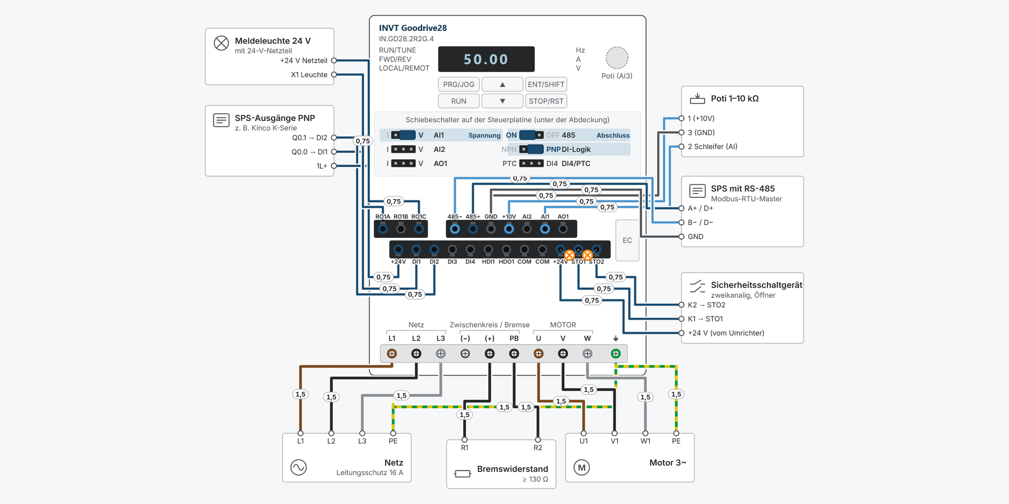
Interaktiver Anschlussplan INVT GD28

Everything for your INVT GD28 after purchase – for all 19 models from 0.2 to 22 kW, single-phase 230 V and three-phase 400 V:

  • Interactive wiring diagram: mains and motor, STO, start/stop, setpoint, Modbus RTU, relay and braking resistor, with cable cross-sections and parameters

  • First steps: commissioning in ten steps, from the motor data to the first run

  • Operation: keypad simulator to try out, with exercises

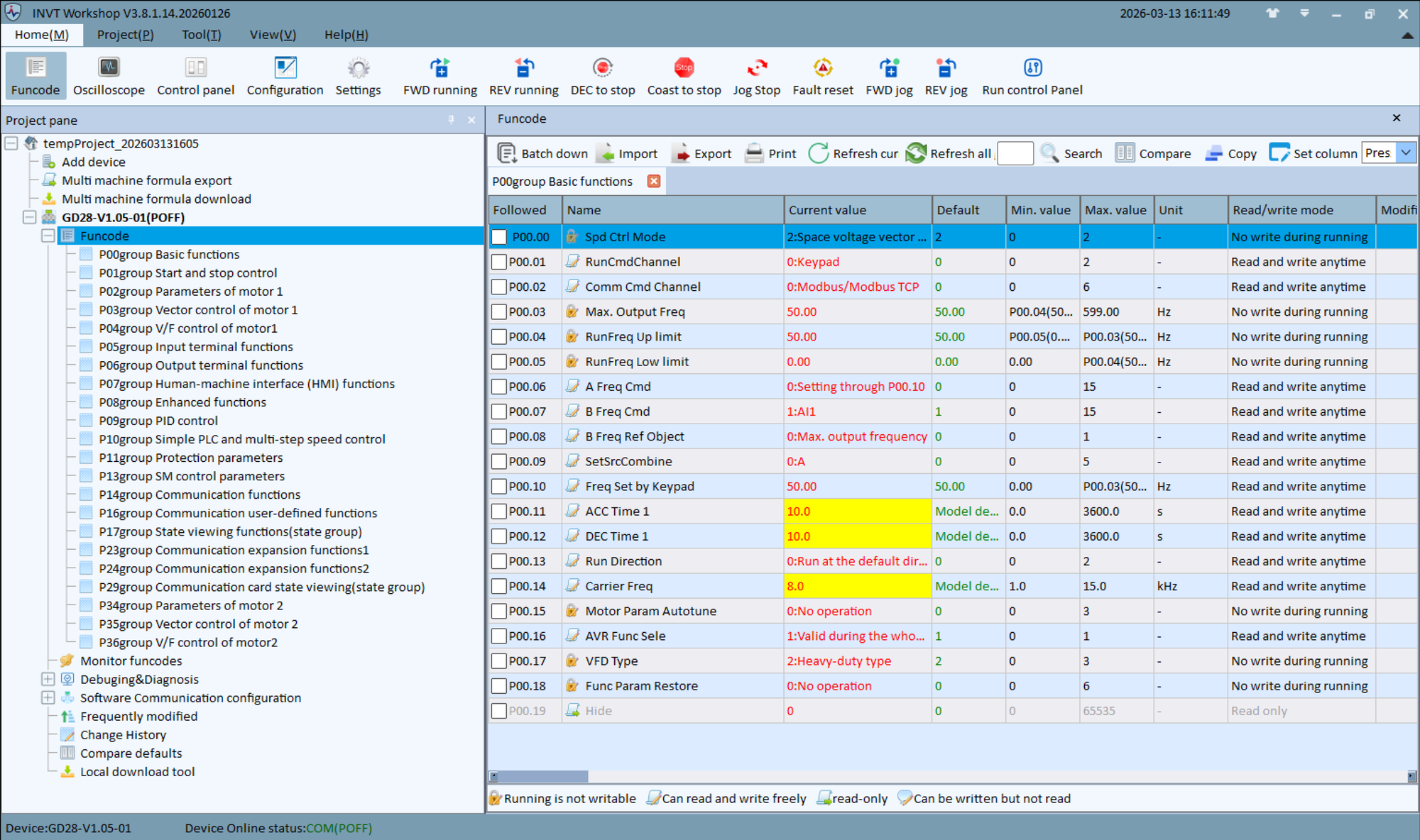
  • Downloads: user manual, catalogue, EC-TX149 manual, GSDML/ESI files, CE, UL and STO certificates and 2D and 3D drawings

  • Free support from spstiger if you get stuck

Keypad: keys, display and LEDs

PRG/JOG opens the menu for setting parameters – the most important key for programming. Try out the keypad here: set parameters, start and stop the motor, reset faults. The exercises guide you step by step through the most important procedures. Rest the mouse pointer on a key for a moment to see what it does right now.

Interactive wiring diagram

Tap a terminal or wire in the drawing to see details.

Terminal overview GD28

TerminalGroupmm²Function
RO1ARELAIS–NO contact of RO1. Rating AC 250 V / 3 A, DC 30 V / 1 A. Function via P06.05 (factory 1 = running).
RO1BRELAIS–NC contact of RO1.
RO1CRELAIS–Common terminal of RO1.
485−STEUER_O–RS-485 B− (Modbus RTU). Shielded twisted pair, 120 Ω termination via slide switch 485.
485+STEUER_O–RS-485 A+ (Modbus RTU).
GNDSTEUER_O–Reference for +10V, analog signals and RS-485.
+10VSTEUER_O–Internal +10.5 V, max. 50 mA, e.g. for a setpoint potentiometer.
AI2STEUER_O–−10–+10 V or 0–20 mA, set slide switch AI2 and P05.76 bit 1 to match.
AI1STEUER_O–0–10 V (33 kΩ) or 0–20 mA (250 Ω), set slide switch AI1 and P05.76 bit 0 to match.
AO1STEUER_O–0–10 V or 0–20 mA, slide switch AO1. Function via P06.26.
+24VSTEUER_U–Internal 24 V, max. 100 mA (together with HDO1 in PNP mode).
DI1STEUER_U–10–30 V = active. Factory: P05.01 = 1 (forward).
DI2STEUER_U–Factory: P05.02 = 4 (jog forward). For reverse, set P05.02 = 2.
DI3STEUER_U–Factory: P05.03 = 7 (fault reset).
DI4STEUER_U–Factory: P05.04 = 0 (no function). With slide switch PTC and P05.04 = 57: PTC thermistor input (trips at 3.6 kΩ).
HDI1STEUER_U–Pulse input up to 50 kHz, with P05.00 = 1 normal digital input.
HDO1STEUER_U–Factory: pulse output (P06.00 = 0), as digital output P06.00 = 1. 50 mA / 30 V.
COMSTEUER_U–Reference of +24V and the digital signals.
COMSTEUER_U–Second COM terminal, internally connected.
+24VSTEUER_U–Second +24V terminal next to the STO inputs. Linked to STO1 and STO2 on delivery.
STO1STEUER_U–13–30 V = enabled, below 5 V = STO active. Linked to +24V on delivery. SIL 3, PL e, Cat. 3.
STO2STEUER_U–Second, redundant channel. Both channels must switch together within 200 ms.
L1 / LLEISTUNG–Mains L1 (3~) or L (S2 models, 1~ 230 V). On frame sizes A–C, L1–L3 are at the top of the unit; the drawing is schematic.
L2 / NLEISTUNG–Mains L2 or N (S2 models).
L3 / –LEISTUNG–Mains L3 (3~ models only).
(−)LEISTUNG–DC link minus. Not for the braking resistor.
(+)LEISTUNG–DC link plus, braking resistor between (+) and PB.
PBLEISTUNG–The brake chopper is built into every GD28; only the resistor is external. Enable with P08.39 = 1.
ULEISTUNG–Motor output U.
VLEISTUNG–Motor output V.
WLEISTUNG–Motor output W.
⏚LEISTUNG–Protective earth (PE). Connect first.

* Clamping range not stated in the manual, derived.

First steps with the INVT GD28

Ten steps from unboxing to the first motor run: connect, clarify STO, enter motor data, set start/stop and setpoint, adjust ramps. You only need digital inputs, Modbus and the braking resistor if your application uses them.

Before connecting
  • Disconnect all supplies and wait at least 5 minutes (manual, all GD28 models). Only then open the cover and touch the terminals.

  • Always connect the protective earth (PE) first. Never apply mains voltage to U, V, W.

  • STO is jumpered at the factory and therefore inactive. If you use STO as a safety function, you need a risk assessment and an acceptance test (step 2).

  1. 1Connect mains and motorRequired

    Mains to L1, L2, L3 (S2 models: L, N), motor to U, V, W, PE to both earthing screws. On frame sizes A–C, the mains terminals are at the top and the motor terminals at the bottom; on D and E, everything is in one row at the bottom.

    The wiring diagram shows the cross-sections, circuit breaker and fuse for your model. The table values in the manual are guide values and must not be undercut.

    The manual recommends symmetrical shielded mains and motor cables. Above the motor cable length given in manual Tab. B-2 (e.g. 2.2 kW: 150 m shielded), an output reactor is required.

    For EMC category C2, add an external mains filter. The matching filter type for your model is shown in the wiring diagram “Mains with EMC filter”.

    Wrong rotation direction: P00.13 = 1 or swap two motor phases.

    Show wiring “Mains and motor”Show wiring “Mains with EMC filter”

    Source: gd28/10-klemmen, 10b-installation, 12-zubehoer-schutzorgane

  2. 2STO: factory jumper or safety circuitRequired

    On delivery, +24V, STO1 and STO2 are jumpered. The inverter runs, but STO is not a safety function.

    For STO, remove the jumpers and wire two NC contacts of a safety relay or emergency stop into the circuits +24V–STO1 and +24V–STO2. Both channels must switch together within 200 ms.

    ParameterValueMeaning
    P08.550After E40, a reset is required (factory default); 1 = message clears automatically

    Displays

    DisplayMeaning
    E40STO active: both channels open
    E41 / E42Channel discrepancy channel 1 / channel 2 – only mains off/on resets
    E43both channels faulty
    E44FLASH CRC error of the STO code – replace the driver board

    If the jumpers are removed without a wired safety circuit, the inverter reports E40 and does not start.

    STO does not replace an emergency stop and does not disconnect the supply. Ratings: SIL 3, PL e, category 3. Cable double-shielded, max. 25 m.

    Carry out and document the acceptance test according to manual appendix F.8 at first commissioning and after every safety-relevant change.

    Show wiring “STO (Safe Torque Off)”

    Practise on the keypad: “Reset STO message E40”

    Source: gd28/11-sto, 10-klemmen §9

  3. 3Enter motor data and motor auto-tuningRequired

    The values are on the motor's rating plate. The parameters of group P02 can only be changed at standstill.

    ParameterValueMeaning
    P02.000Motor type: 0 = asynchronous motor (factory default), 1 = permanent magnet synchronous motor
    P02.01Rating plateRated power in kW
    P02.02Rating plateRated frequency, in Europe usually 50.00 Hz
    P02.03Rating plateRated speed in min⁻¹
    P02.04Rating plateRated voltage in V
    P02.05Rating plateRated current in A
    P00.000, 1 or 2Control mode: 2 = SVPWM/V/f (factory default), 0 or 1 = sensorless vector control (only after auto-tuning)

    Motor auto-tuning

    1. P00.01 = 0 (start via the keypad).

    2. Enter P02.01 to P02.05 from the rating plate.

    3. Select P00.15: 1 = full rotating (uncouple the motor from the load), 2 = full static, 3 = partial static. Confirm with ENT/SHIFT; the display shows -TUN-.

    4. Press RUN. The display counts the steps (TUN-1 …), RUN/TUNE flashes.

    5. At -End-, auto-tuning is complete; the determined motor parameters are saved.

    Practise on the keypad: “Enter motor data and run motor auto-tuning”

    Source: gd28/01-basis, manual chap. 6.2.1

  4. 4Set the start/stop sourceRequired

    P00.01 determines where the start command comes from. The digital inputs are set to PNP at the factory (NPN/PNP slide switch): the contact is between +24V and DIx.

    ParameterValueMeaning
    P00.010 / 1 / 20 = keypad (factory default), 1 = terminals, 2 = communication
    P05.011DI1 = forward (factory default)
    P05.022DI2 = reverse – factory default is 4 = jog forward
    P07.040–3Effect of the STOP/RST key with terminal or communication control (factory 0 = keypad only)

    DI3 is fault reset at the factory (P05.03 = 7).

    LOCAL/REMOT shows the command source: off = keypad, flashing = terminals, on = communication.

    Show wiring “Start/stop via switch”Show wiring “Start/stop from PLC (PNP)”

    Practise on the keypad: “Start and stop the motor from the keypad”Practise on the keypad: “Switch the run command to terminals”

    Source: gd28/01-basis, 02-io, 03-io-hmi

  5. 5Set the setpointRequired
    ParameterValueMeaning
    P00.060 / 1 / 2 / 3 / 10Frequency setpoint A: 0 = P00.10 (factory), 1 = AI1, 2 = AI2, 3 = AI3 (keypad potentiometer), 10 = Modbus
    P00.1050.00 HzFrequency setting via the keypad (factory)
    P00.0350.00 HzMaximum output frequency, reference for setpoints and ramps (only at standstill)
    P00.04 / P00.0550.00 / 0.00 HzUpper and lower limit of the running frequency
    P05.760x0 / 0x1AI signal type: bit 0 = AI1, bit 1 = AI2, 1 = current

    AI1/AI2 slide switches and P05.76 must match, otherwise the analog setpoint will be wrong.

    For 4–20 mA at AI1: switch to I, P05.76 = 0x1; in current mode, the lower limit P05.42 is set to 4.00 mA at the factory.

    Show wiring “Setpoint via potentiometer”Show wiring “Setpoint 4–20 mA from PLC”

    Practise on the keypad: “Set frequency setting P00.10 to 15.00 Hz”Practise on the keypad: “Setpoint via the potentiometer (AI3)”

    Source: gd28/01-basis, 02-io, 10-klemmen §6

  6. 6Set acceleration and deceleration timeOptional
    ParameterValueMeaning
    P00.11model-dependentAcceleration time 1 from 0 Hz to P00.03 (0.0–3600.0 s)
    P00.12model-dependentDeceleration time 1 from P00.03 to 0 Hz

    A deceleration time that is too short with a large flywheel mass leads to E8 (overvoltage during deceleration). Then extend the deceleration time or connect a braking resistor (step 9).

    Practise on the keypad: “Set acceleration time P00.11 to 5.0 s”

    Source: gd28/01-basis

  7. 7Assign digital inputs and relaysOptional

    Factory defaults

    TerminalParameterFactoryMeaning
    DI1P05.011Forward
    DI2P05.024Jog forward
    DI3P05.037Fault reset
    DI4P05.040no function (with switch PTC and 57: PTC thermistor)
    HDI1P05.000Pulse input; with 1 normal digital input
    RO1P06.051running; 5 = inverter in fault state

    Further functions: 2 = reverse, 3 = three-wire run control, 5 = jog reverse (function list 0–95 in the manual).

    HDO1 is a pulse output at the factory; as a digital output P06.00 = 1.

    PTC thermistor in the motor: connect to DI4 and COM, set slide switch DI4/PTC to PTC, P05.04 = 57. On overtemperature the inverter stops with E59.

    Show wiring “Fault signal via relay”Show wiring “Motor temperature (PTC) at DI4”

    Source: gd28/02-io

  8. 8Set up Modbus RTU or EthernetOptional
    ParameterValueMeaning
    P00.012Start command via communication
    P00.0610Frequency setpoint via Modbus/Modbus TCP (on the GD27 it would be 8)
    P14.001Slave address (factory)
    P14.01419200 bit/s (factory)
    P14.021E, 8, 1 (factory)
    P14.040.0 sTimeout off (factory); otherwise fault E18 if telegrams stop arriving

    Control word 0x2000: 1 = forward, 5 = stop, 7 = fault reset. Frequency setpoint 0x2001 in 0.01 Hz.

    Internal 120 Ω termination via the 485 slide switch: set to ON only at the two bus ends.

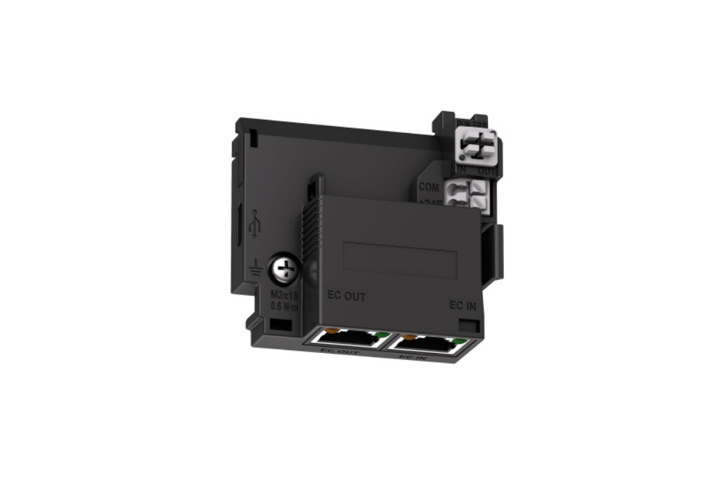
    Ethernet (PROFINET, EtherCAT, EtherNet/IP, Modbus TCP) via the EC-TX149 card: protocol in P24.00, frequency setpoint P00.06 = 14 (or 10 for Modbus TCP).

    Show wiring “Modbus RTU to PLC”

    Source: gd28/04-modbus, 13-ec-tx149-kommunikation, 10-klemmen §10

  9. 9Connect a braking resistorOptional

    The brake chopper is built into every GD28; only the resistor is external: between (+) and PB, never to (−).

    ParameterValueMeaning
    P08.391Enable dynamic braking – factory default 0 = off
    P08.40700.0 VSwitch-on threshold for 400 V models (220 V models: 380.0 V)

    Never go below the minimum resistance from manual Tab. E-6, otherwise the chopper will be destroyed. The wiring diagram shows the values for each model.

    Without P08.39 = 1, the resistor stays cold; the inverter then extends the ramp via the overvoltage protection (P11.03).

    Show wiring “Braking resistor”

    Practise on the keypad: “Reset fault E8”

    Source: gd28/06-schutz, 12-zubehoer-schutzorgane

  10. 10First runRequired

    Group P17 provides the operating values (e.g. P17.04 output current, P17.11 DC link voltage), the fault memory P07.27 ff.

    Practise on the keypad: “Start and stop the motor from the keypad”Practise on the keypad: “Read operating values (P17) and fault memory (P07)”

    Source: gd28/01-basis, 08-monitor, 03-io-hmi

Revision 2.0 · 26.09.2026 · Source: INVT GD28 Manual V1.3 (03/2026), prepared in spstiger vfd-konfig (gd28/01-basis, 02-io, 03-io-hmi, 04-modbus, 06-schutz, 10-klemmen, 10b-installation, 11-sto, 12-zubehoer-schutzorgane). The manufacturer manual and applicable standards take precedence; installation and commissioning by a qualified electrician only.

Multi-speed operation

Select preset frequencies via digital inputs: step by step for the GD28.

Open the guide: Multi-speed operation INVT GD28

Stuck?

Our support helps you free of charge. Tell us what you are planning and which model you use – via the contact form, by email or in the community forum.

More ways to contact us: Support contacts

Downloads

User manual, catalogue, EC-TX149 manual, GSDML/ESI files, CE, UL and STO certificates and 2D and 3D drawings:

INVT GD28

INVT GD28 Frequenzumrichter

INVT GD28-0R2G-S2 frequency inverter with STO and optional communication card
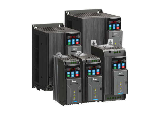
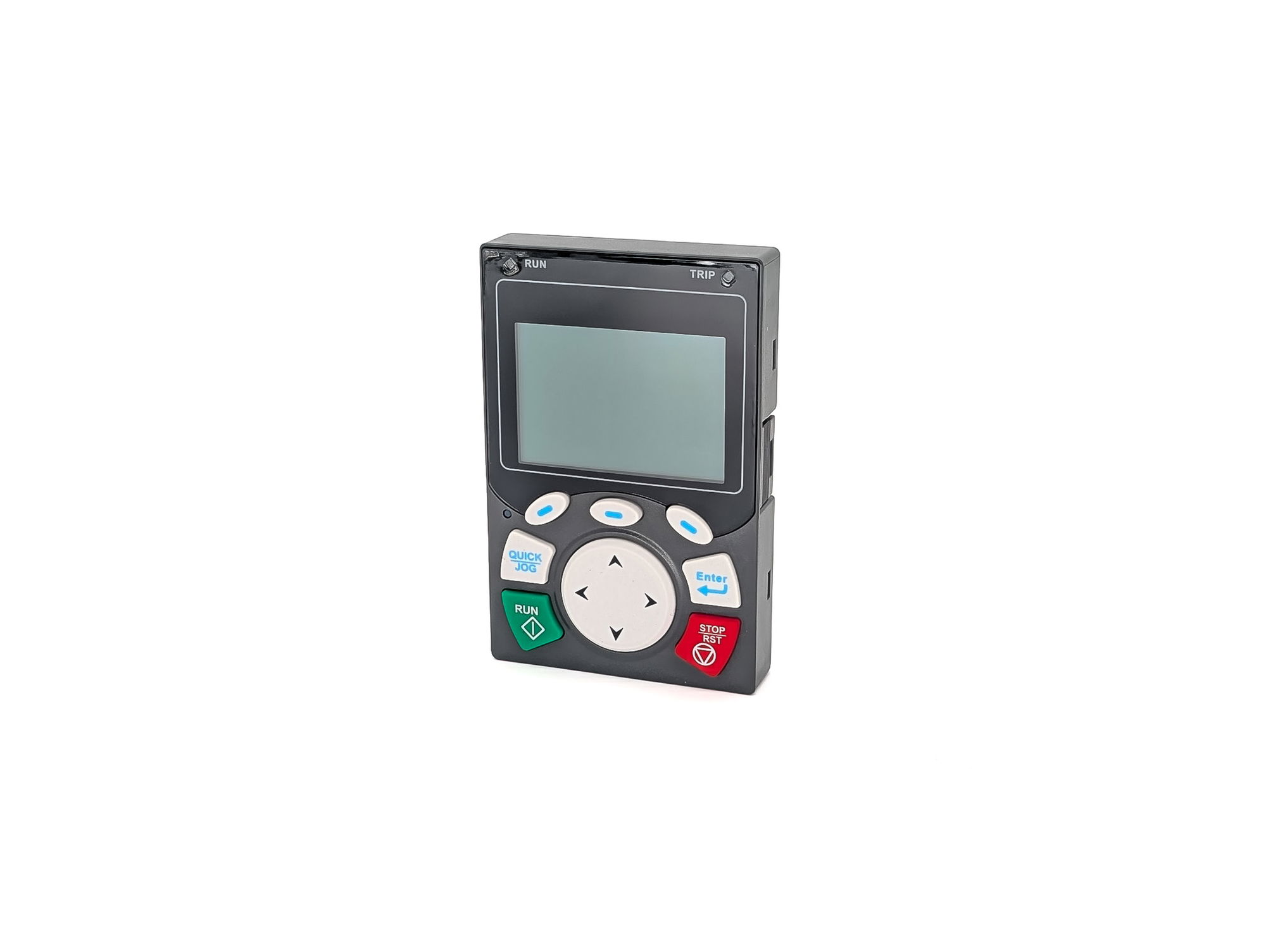
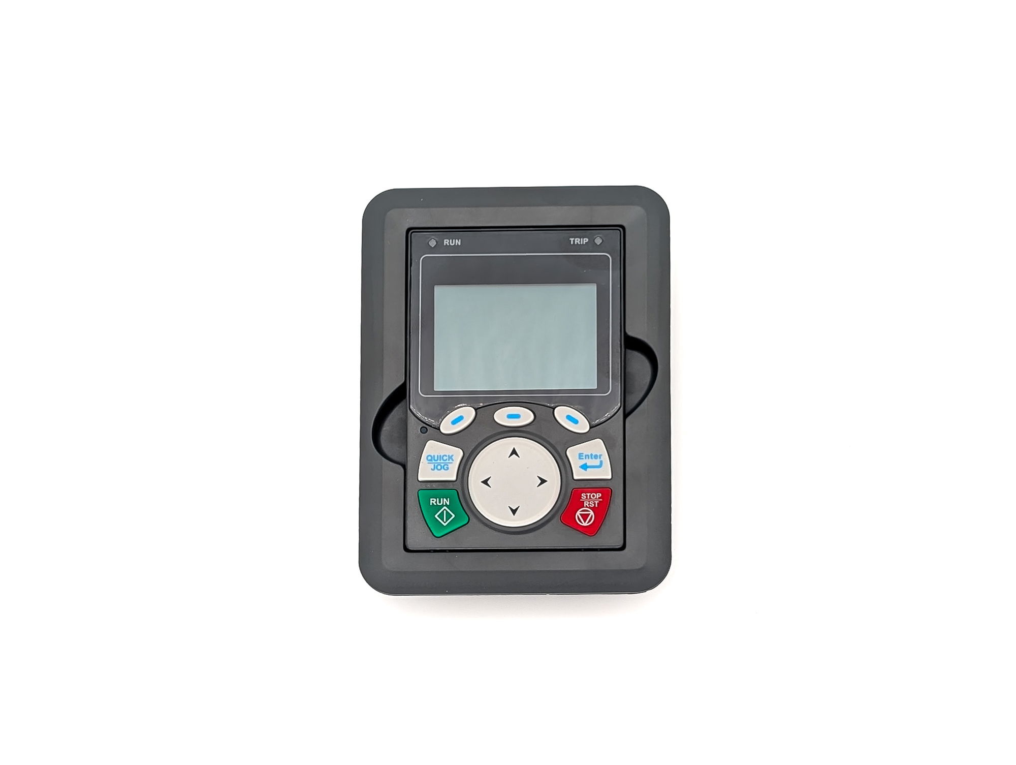
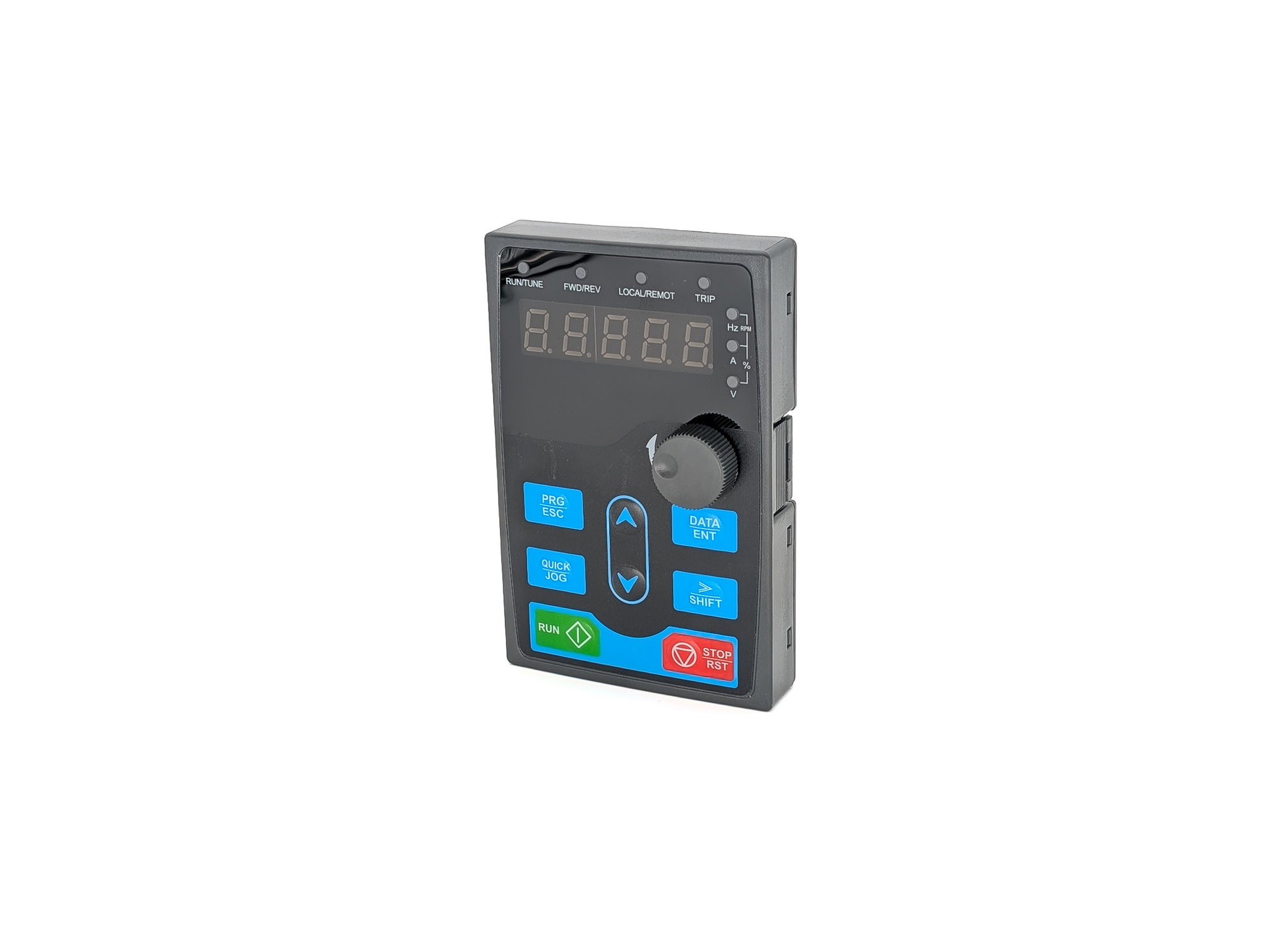
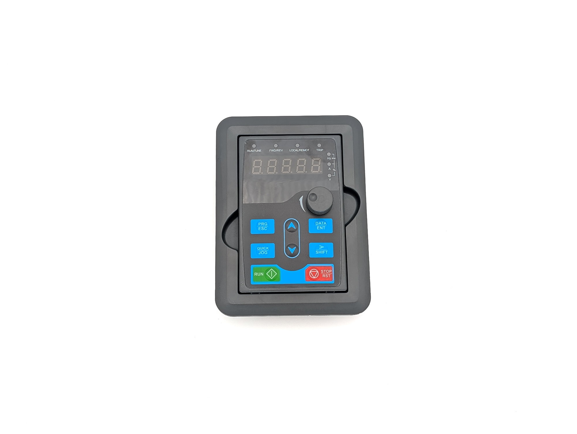
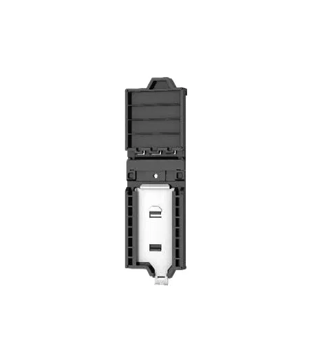
If you need a compact frequency inverter with built-in STO, brake chopper and EMC filter that can be integrated into PROFINET, EtherCAT, EtherNet/IP or Modbus TCP when required, the INVT GD28 is a universal inverter from 0.2 to 2.2 kW for single-phase 230 V and 0.4 to 22 kW for three-phase 400 V. Modbus RTU comes as standard; a single card covers all Ethernet fieldbuses: the EC-TX149. 🏭 Typical Applications Packaging, printing and machine tools: STO to SIL 3 / PL e is built into every model. According to INVT, sensorless vector control delivers up to 200 % starting torque at 0.5 Hz, with a torque response below 10 ms. Pumps, fans and compressors: integrated PID controller, energy-saving control at partial load and speed tracking for a smooth restart of a coasting motor. In light-duty mode, one unit covers the next larger motor rating. Conveyors, mixers and filling machines: linear or S-curve ramps, up to 16 preset speeds and ride-through during short mains dips. Plants with different fieldbuses: The EC-TX149 handles PROFINET, EtherCAT, EtherNet/IP and Modbus TCP — the protocol is selected by parameter. One card type in stock instead of four. ⚙️ Control and Functions Two control modes: V/f control and sensorless vector control (SVC) with a speed range of 1:100 and ±0.2 % speed accuracy. Asynchronous and permanent-magnet synchronous motors, autotuning of motor parameters. Dual rating: heavy duty 150 % for 60 s and 180 % for 10 s, light duty 110 % for 60 s and 150 % for 10 s. Output frequency 0–599 Hz, frequency resolution 0.01 Hz. Frequency setpoint via keypad, potentiometer, analog input, pulse input, preset speeds, PID or Modbus — setpoint channels can be combined. Motor temperature monitoring: PTC directly on DI4, PT100, PT1000 or KTY84 via the AO→AI analog combination. Fewer nuisance trips: overvoltage and overcurrent stall control, automatic voltage regulation (AVR). 🔌 Connections and Control I/O 5 digital inputs: 4 standard inputs and 1 high-speed input up to 50 kHz, NPN and PNP (factory setting PNP). 2 analog inputs: AI1 0–10 V or 0–20 mA, AI2 −10–+10 V or 0–20 mA. 1 analog output 0–10 V or 0–20 mA and 1 high-speed digital output up to 50 kHz. 1 relay output: changeover contact, 250 V AC / 3 A or 30 V DC / 1 A. RS-485 with Modbus RTU as terminal, RJ45 for the external keypad. USB-C: parameter setting, parameter copy and monitoring with the INVT Workshop software — the PC powers the control electronics, no mains voltage and no interface converter needed. Spring-clamp terminals for the control wiring, one slot for expansion cards. ⚠️ Before Ordering Select by output current, not by kW: The motor rated current must match the inverter's output current. The kW figure in the model name applies to heavy duty and a standard four-pole motor. EMC filter: With the built-in filter, the single-phase models meet category C2, the three-phase models C3. C2 on three-phase units requires an external filter. External brake resistor: The brake chopper is built in; the resistor is connected to (+)/PB. Do not go below the minimum resistance for each power rating. Using STO: The STO inputs are jumpered at the factory. If STO is part of your safety concept, remove the jumpers and wire a safety relay or safety PLC. Keypads: A simple LED keypad is built in. For the cabinet door, the BOP-270 (LED) and SOP-28 (LCD) keypads are available. While a USB-C cable is plugged in, the external keypad is disabled. 🔧 Frame Sizes, Environment and Mounting Frame A (230 V: 0.2–0.75 kW · 400 V: 0.4–1.1 kW): 60 × 190 × 155 mm, approx. 1.25 kg, fanless Frame B (230 V: 1.1–2.2 kW · 400 V: 1.5–4 kW): 70 × 190 × 155 mm, approx. 1.3 kg Frame C (400 V: 5.5–7.5 kW): 90 × 235 × 155 mm, approx. 2.1 kg Frame D (400 V: 11–15 kW): 130 × 250 × 185 mm, approx. 3.55 kg Frame E (400 V: 18.5–22 kW): 160 × 300 × 190 mm, approx. 4.9 kg Mounting: wall mounting with two screws (A/B), DIN rail with the AP-RB-A-01 adapter (A/B), flange mounting with the heat sink outside the cabinet (C/D/E). Below 40 °C ambient temperature, units may be mounted side by side without clearance. IP20. Operation −10 °C to +50 °C (heavy duty without derating), storage −20 °C to +70 °C, humidity below 95 % non-condensing, above 1000 m 1 % derating per 100 m. Coated PCBs to 3C2/3S2. 🏷️ Manufacturer and Reliability INVT Electric from Shenzhen is one of the major Chinese manufacturers of drive technology. The GD28 is certified to CE, UL and TÜV; all models reach efficiency class IE2. INVT frequency inverters are in productive use at numerous spstiger customers — with support in German directly from us.
From €82.08 *

Preis exkl. MwSt., zzgl. Versandkosten

INVT GD28-0R4G-S2 frequency inverter with STO and optional communication card
If you need a compact frequency inverter with built-in STO, brake chopper and EMC filter that can be integrated into PROFINET, EtherCAT, EtherNet/IP or Modbus TCP when required, the INVT GD28 is a universal inverter from 0.2 to 2.2 kW for single-phase 230 V and 0.4 to 22 kW for three-phase 400 V. Modbus RTU comes as standard; a single card covers all Ethernet fieldbuses: the EC-TX149. 🏭 Typical Applications Packaging, printing and machine tools: STO to SIL 3 / PL e is built into every model. According to INVT, sensorless vector control delivers up to 200 % starting torque at 0.5 Hz, with a torque response below 10 ms. Pumps, fans and compressors: integrated PID controller, energy-saving control at partial load and speed tracking for a smooth restart of a coasting motor. In light-duty mode, one unit covers the next larger motor rating. Conveyors, mixers and filling machines: linear or S-curve ramps, up to 16 preset speeds and ride-through during short mains dips. Plants with different fieldbuses: The EC-TX149 handles PROFINET, EtherCAT, EtherNet/IP and Modbus TCP — the protocol is selected by parameter. One card type in stock instead of four. ⚙️ Control and Functions Two control modes: V/f control and sensorless vector control (SVC) with a speed range of 1:100 and ±0.2 % speed accuracy. Asynchronous and permanent-magnet synchronous motors, autotuning of motor parameters. Dual rating: heavy duty 150 % for 60 s and 180 % for 10 s, light duty 110 % for 60 s and 150 % for 10 s. Output frequency 0–599 Hz, frequency resolution 0.01 Hz. Frequency setpoint via keypad, potentiometer, analog input, pulse input, preset speeds, PID or Modbus — setpoint channels can be combined. Motor temperature monitoring: PTC directly on DI4, PT100, PT1000 or KTY84 via the AO→AI analog combination. Fewer nuisance trips: overvoltage and overcurrent stall control, automatic voltage regulation (AVR). 🔌 Connections and Control I/O 5 digital inputs: 4 standard inputs and 1 high-speed input up to 50 kHz, NPN and PNP (factory setting PNP). 2 analog inputs: AI1 0–10 V or 0–20 mA, AI2 −10–+10 V or 0–20 mA. 1 analog output 0–10 V or 0–20 mA and 1 high-speed digital output up to 50 kHz. 1 relay output: changeover contact, 250 V AC / 3 A or 30 V DC / 1 A. RS-485 with Modbus RTU as terminal, RJ45 for the external keypad. USB-C: parameter setting, parameter copy and monitoring with the INVT Workshop software — the PC powers the control electronics, no mains voltage and no interface converter needed. Spring-clamp terminals for the control wiring, one slot for expansion cards. ⚠️ Before Ordering Select by output current, not by kW: The motor rated current must match the inverter's output current. The kW figure in the model name applies to heavy duty and a standard four-pole motor. EMC filter: With the built-in filter, the single-phase models meet category C2, the three-phase models C3. C2 on three-phase units requires an external filter. External brake resistor: The brake chopper is built in; the resistor is connected to (+)/PB. Do not go below the minimum resistance for each power rating. Using STO: The STO inputs are jumpered at the factory. If STO is part of your safety concept, remove the jumpers and wire a safety relay or safety PLC. Keypads: A simple LED keypad is built in. For the cabinet door, the BOP-270 (LED) and SOP-28 (LCD) keypads are available. While a USB-C cable is plugged in, the external keypad is disabled. 🔧 Frame Sizes, Environment and Mounting Frame A (230 V: 0.2–0.75 kW · 400 V: 0.4–1.1 kW): 60 × 190 × 155 mm, approx. 1.25 kg, fanless Frame B (230 V: 1.1–2.2 kW · 400 V: 1.5–4 kW): 70 × 190 × 155 mm, approx. 1.3 kg Frame C (400 V: 5.5–7.5 kW): 90 × 235 × 155 mm, approx. 2.1 kg Frame D (400 V: 11–15 kW): 130 × 250 × 185 mm, approx. 3.55 kg Frame E (400 V: 18.5–22 kW): 160 × 300 × 190 mm, approx. 4.9 kg Mounting: wall mounting with two screws (A/B), DIN rail with the AP-RB-A-01 adapter (A/B), flange mounting with the heat sink outside the cabinet (C/D/E). Below 40 °C ambient temperature, units may be mounted side by side without clearance. IP20. Operation −10 °C to +50 °C (heavy duty without derating), storage −20 °C to +70 °C, humidity below 95 % non-condensing, above 1000 m 1 % derating per 100 m. Coated PCBs to 3C2/3S2. 🏷️ Manufacturer and Reliability INVT Electric from Shenzhen is one of the major Chinese manufacturers of drive technology. The GD28 is certified to CE, UL and TÜV; all models reach efficiency class IE2. INVT frequency inverters are in productive use at numerous spstiger customers — with support in German directly from us.
Variants from €82.08 *
From €85.12 *

Preis exkl. MwSt., zzgl. Versandkosten

INVT GD28-0R7G-S2 frequency inverter with STO and optional communication card
If you need a compact frequency inverter with built-in STO, brake chopper and EMC filter that can be integrated into PROFINET, EtherCAT, EtherNet/IP or Modbus TCP when required, the INVT GD28 is a universal inverter from 0.2 to 2.2 kW for single-phase 230 V and 0.4 to 22 kW for three-phase 400 V. Modbus RTU comes as standard; a single card covers all Ethernet fieldbuses: the EC-TX149. 🏭 Typical Applications Packaging, printing and machine tools: STO to SIL 3 / PL e is built into every model. According to INVT, sensorless vector control delivers up to 200 % starting torque at 0.5 Hz, with a torque response below 10 ms. Pumps, fans and compressors: integrated PID controller, energy-saving control at partial load and speed tracking for a smooth restart of a coasting motor. In light-duty mode, one unit covers the next larger motor rating. Conveyors, mixers and filling machines: linear or S-curve ramps, up to 16 preset speeds and ride-through during short mains dips. Plants with different fieldbuses: The EC-TX149 handles PROFINET, EtherCAT, EtherNet/IP and Modbus TCP — the protocol is selected by parameter. One card type in stock instead of four. ⚙️ Control and Functions Two control modes: V/f control and sensorless vector control (SVC) with a speed range of 1:100 and ±0.2 % speed accuracy. Asynchronous and permanent-magnet synchronous motors, autotuning of motor parameters. Dual rating: heavy duty 150 % for 60 s and 180 % for 10 s, light duty 110 % for 60 s and 150 % for 10 s. Output frequency 0–599 Hz, frequency resolution 0.01 Hz. Frequency setpoint via keypad, potentiometer, analog input, pulse input, preset speeds, PID or Modbus — setpoint channels can be combined. Motor temperature monitoring: PTC directly on DI4, PT100, PT1000 or KTY84 via the AO→AI analog combination. Fewer nuisance trips: overvoltage and overcurrent stall control, automatic voltage regulation (AVR). 🔌 Connections and Control I/O 5 digital inputs: 4 standard inputs and 1 high-speed input up to 50 kHz, NPN and PNP (factory setting PNP). 2 analog inputs: AI1 0–10 V or 0–20 mA, AI2 −10–+10 V or 0–20 mA. 1 analog output 0–10 V or 0–20 mA and 1 high-speed digital output up to 50 kHz. 1 relay output: changeover contact, 250 V AC / 3 A or 30 V DC / 1 A. RS-485 with Modbus RTU as terminal, RJ45 for the external keypad. USB-C: parameter setting, parameter copy and monitoring with the INVT Workshop software — the PC powers the control electronics, no mains voltage and no interface converter needed. Spring-clamp terminals for the control wiring, one slot for expansion cards. ⚠️ Before Ordering Select by output current, not by kW: The motor rated current must match the inverter's output current. The kW figure in the model name applies to heavy duty and a standard four-pole motor. EMC filter: With the built-in filter, the single-phase models meet category C2, the three-phase models C3. C2 on three-phase units requires an external filter. External brake resistor: The brake chopper is built in; the resistor is connected to (+)/PB. Do not go below the minimum resistance for each power rating. Using STO: The STO inputs are jumpered at the factory. If STO is part of your safety concept, remove the jumpers and wire a safety relay or safety PLC. Keypads: A simple LED keypad is built in. For the cabinet door, the BOP-270 (LED) and SOP-28 (LCD) keypads are available. While a USB-C cable is plugged in, the external keypad is disabled. 🔧 Frame Sizes, Environment and Mounting Frame A (230 V: 0.2–0.75 kW · 400 V: 0.4–1.1 kW): 60 × 190 × 155 mm, approx. 1.25 kg, fanless Frame B (230 V: 1.1–2.2 kW · 400 V: 1.5–4 kW): 70 × 190 × 155 mm, approx. 1.3 kg Frame C (400 V: 5.5–7.5 kW): 90 × 235 × 155 mm, approx. 2.1 kg Frame D (400 V: 11–15 kW): 130 × 250 × 185 mm, approx. 3.55 kg Frame E (400 V: 18.5–22 kW): 160 × 300 × 190 mm, approx. 4.9 kg Mounting: wall mounting with two screws (A/B), DIN rail with the AP-RB-A-01 adapter (A/B), flange mounting with the heat sink outside the cabinet (C/D/E). Below 40 °C ambient temperature, units may be mounted side by side without clearance. IP20. Operation −10 °C to +50 °C (heavy duty without derating), storage −20 °C to +70 °C, humidity below 95 % non-condensing, above 1000 m 1 % derating per 100 m. Coated PCBs to 3C2/3S2. 🏷️ Manufacturer and Reliability INVT Electric from Shenzhen is one of the major Chinese manufacturers of drive technology. The GD28 is certified to CE, UL and TÜV; all models reach efficiency class IE2. INVT frequency inverters are in productive use at numerous spstiger customers — with support in German directly from us.
Variants from €82.08 *
From €85.12 *

Preis exkl. MwSt., zzgl. Versandkosten

INVT GD28-1R1G-S2 frequency inverter with STO and optional communication card
If you need a compact frequency inverter with built-in STO, brake chopper and EMC filter that can be integrated into PROFINET, EtherCAT, EtherNet/IP or Modbus TCP when required, the INVT GD28 is a universal inverter from 0.2 to 2.2 kW for single-phase 230 V and 0.4 to 22 kW for three-phase 400 V. Modbus RTU comes as standard; a single card covers all Ethernet fieldbuses: the EC-TX149. 🏭 Typical Applications Packaging, printing and machine tools: STO to SIL 3 / PL e is built into every model. According to INVT, sensorless vector control delivers up to 200 % starting torque at 0.5 Hz, with a torque response below 10 ms. Pumps, fans and compressors: integrated PID controller, energy-saving control at partial load and speed tracking for a smooth restart of a coasting motor. In light-duty mode, one unit covers the next larger motor rating. Conveyors, mixers and filling machines: linear or S-curve ramps, up to 16 preset speeds and ride-through during short mains dips. Plants with different fieldbuses: The EC-TX149 handles PROFINET, EtherCAT, EtherNet/IP and Modbus TCP — the protocol is selected by parameter. One card type in stock instead of four. ⚙️ Control and Functions Two control modes: V/f control and sensorless vector control (SVC) with a speed range of 1:100 and ±0.2 % speed accuracy. Asynchronous and permanent-magnet synchronous motors, autotuning of motor parameters. Dual rating: heavy duty 150 % for 60 s and 180 % for 10 s, light duty 110 % for 60 s and 150 % for 10 s. Output frequency 0–599 Hz, frequency resolution 0.01 Hz. Frequency setpoint via keypad, potentiometer, analog input, pulse input, preset speeds, PID or Modbus — setpoint channels can be combined. Motor temperature monitoring: PTC directly on DI4, PT100, PT1000 or KTY84 via the AO→AI analog combination. Fewer nuisance trips: overvoltage and overcurrent stall control, automatic voltage regulation (AVR). 🔌 Connections and Control I/O 5 digital inputs: 4 standard inputs and 1 high-speed input up to 50 kHz, NPN and PNP (factory setting PNP). 2 analog inputs: AI1 0–10 V or 0–20 mA, AI2 −10–+10 V or 0–20 mA. 1 analog output 0–10 V or 0–20 mA and 1 high-speed digital output up to 50 kHz. 1 relay output: changeover contact, 250 V AC / 3 A or 30 V DC / 1 A. RS-485 with Modbus RTU as terminal, RJ45 for the external keypad. USB-C: parameter setting, parameter copy and monitoring with the INVT Workshop software — the PC powers the control electronics, no mains voltage and no interface converter needed. Spring-clamp terminals for the control wiring, one slot for expansion cards. ⚠️ Before Ordering Select by output current, not by kW: The motor rated current must match the inverter's output current. The kW figure in the model name applies to heavy duty and a standard four-pole motor. EMC filter: With the built-in filter, the single-phase models meet category C2, the three-phase models C3. C2 on three-phase units requires an external filter. External brake resistor: The brake chopper is built in; the resistor is connected to (+)/PB. Do not go below the minimum resistance for each power rating. Using STO: The STO inputs are jumpered at the factory. If STO is part of your safety concept, remove the jumpers and wire a safety relay or safety PLC. Keypads: A simple LED keypad is built in. For the cabinet door, the BOP-270 (LED) and SOP-28 (LCD) keypads are available. While a USB-C cable is plugged in, the external keypad is disabled. 🔧 Frame Sizes, Environment and Mounting Frame A (230 V: 0.2–0.75 kW · 400 V: 0.4–1.1 kW): 60 × 190 × 155 mm, approx. 1.25 kg, fanless Frame B (230 V: 1.1–2.2 kW · 400 V: 1.5–4 kW): 70 × 190 × 155 mm, approx. 1.3 kg Frame C (400 V: 5.5–7.5 kW): 90 × 235 × 155 mm, approx. 2.1 kg Frame D (400 V: 11–15 kW): 130 × 250 × 185 mm, approx. 3.55 kg Frame E (400 V: 18.5–22 kW): 160 × 300 × 190 mm, approx. 4.9 kg Mounting: wall mounting with two screws (A/B), DIN rail with the AP-RB-A-01 adapter (A/B), flange mounting with the heat sink outside the cabinet (C/D/E). Below 40 °C ambient temperature, units may be mounted side by side without clearance. IP20. Operation −10 °C to +50 °C (heavy duty without derating), storage −20 °C to +70 °C, humidity below 95 % non-condensing, above 1000 m 1 % derating per 100 m. Coated PCBs to 3C2/3S2. 🏷️ Manufacturer and Reliability INVT Electric from Shenzhen is one of the major Chinese manufacturers of drive technology. The GD28 is certified to CE, UL and TÜV; all models reach efficiency class IE2. INVT frequency inverters are in productive use at numerous spstiger customers — with support in German directly from us.
Variants from €82.08 *
From €101.84 *

Preis exkl. MwSt., zzgl. Versandkosten

INVT GD28-1R5G-S2 frequency inverter with STO and optional communication card
If you need a compact frequency inverter with built-in STO, brake chopper and EMC filter that can be integrated into PROFINET, EtherCAT, EtherNet/IP or Modbus TCP when required, the INVT GD28 is a universal inverter from 0.2 to 2.2 kW for single-phase 230 V and 0.4 to 22 kW for three-phase 400 V. Modbus RTU comes as standard; a single card covers all Ethernet fieldbuses: the EC-TX149. 🏭 Typical Applications Packaging, printing and machine tools: STO to SIL 3 / PL e is built into every model. According to INVT, sensorless vector control delivers up to 200 % starting torque at 0.5 Hz, with a torque response below 10 ms. Pumps, fans and compressors: integrated PID controller, energy-saving control at partial load and speed tracking for a smooth restart of a coasting motor. In light-duty mode, one unit covers the next larger motor rating. Conveyors, mixers and filling machines: linear or S-curve ramps, up to 16 preset speeds and ride-through during short mains dips. Plants with different fieldbuses: The EC-TX149 handles PROFINET, EtherCAT, EtherNet/IP and Modbus TCP — the protocol is selected by parameter. One card type in stock instead of four. ⚙️ Control and Functions Two control modes: V/f control and sensorless vector control (SVC) with a speed range of 1:100 and ±0.2 % speed accuracy. Asynchronous and permanent-magnet synchronous motors, autotuning of motor parameters. Dual rating: heavy duty 150 % for 60 s and 180 % for 10 s, light duty 110 % for 60 s and 150 % for 10 s. Output frequency 0–599 Hz, frequency resolution 0.01 Hz. Frequency setpoint via keypad, potentiometer, analog input, pulse input, preset speeds, PID or Modbus — setpoint channels can be combined. Motor temperature monitoring: PTC directly on DI4, PT100, PT1000 or KTY84 via the AO→AI analog combination. Fewer nuisance trips: overvoltage and overcurrent stall control, automatic voltage regulation (AVR). 🔌 Connections and Control I/O 5 digital inputs: 4 standard inputs and 1 high-speed input up to 50 kHz, NPN and PNP (factory setting PNP). 2 analog inputs: AI1 0–10 V or 0–20 mA, AI2 −10–+10 V or 0–20 mA. 1 analog output 0–10 V or 0–20 mA and 1 high-speed digital output up to 50 kHz. 1 relay output: changeover contact, 250 V AC / 3 A or 30 V DC / 1 A. RS-485 with Modbus RTU as terminal, RJ45 for the external keypad. USB-C: parameter setting, parameter copy and monitoring with the INVT Workshop software — the PC powers the control electronics, no mains voltage and no interface converter needed. Spring-clamp terminals for the control wiring, one slot for expansion cards. ⚠️ Before Ordering Select by output current, not by kW: The motor rated current must match the inverter's output current. The kW figure in the model name applies to heavy duty and a standard four-pole motor. EMC filter: With the built-in filter, the single-phase models meet category C2, the three-phase models C3. C2 on three-phase units requires an external filter. External brake resistor: The brake chopper is built in; the resistor is connected to (+)/PB. Do not go below the minimum resistance for each power rating. Using STO: The STO inputs are jumpered at the factory. If STO is part of your safety concept, remove the jumpers and wire a safety relay or safety PLC. Keypads: A simple LED keypad is built in. For the cabinet door, the BOP-270 (LED) and SOP-28 (LCD) keypads are available. While a USB-C cable is plugged in, the external keypad is disabled. 🔧 Frame Sizes, Environment and Mounting Frame A (230 V: 0.2–0.75 kW · 400 V: 0.4–1.1 kW): 60 × 190 × 155 mm, approx. 1.25 kg, fanless Frame B (230 V: 1.1–2.2 kW · 400 V: 1.5–4 kW): 70 × 190 × 155 mm, approx. 1.3 kg Frame C (400 V: 5.5–7.5 kW): 90 × 235 × 155 mm, approx. 2.1 kg Frame D (400 V: 11–15 kW): 130 × 250 × 185 mm, approx. 3.55 kg Frame E (400 V: 18.5–22 kW): 160 × 300 × 190 mm, approx. 4.9 kg Mounting: wall mounting with two screws (A/B), DIN rail with the AP-RB-A-01 adapter (A/B), flange mounting with the heat sink outside the cabinet (C/D/E). Below 40 °C ambient temperature, units may be mounted side by side without clearance. IP20. Operation −10 °C to +50 °C (heavy duty without derating), storage −20 °C to +70 °C, humidity below 95 % non-condensing, above 1000 m 1 % derating per 100 m. Coated PCBs to 3C2/3S2. 🏷️ Manufacturer and Reliability INVT Electric from Shenzhen is one of the major Chinese manufacturers of drive technology. The GD28 is certified to CE, UL and TÜV; all models reach efficiency class IE2. INVT frequency inverters are in productive use at numerous spstiger customers — with support in German directly from us.
Variants from €82.08 *
From €110.96 *

Preis exkl. MwSt., zzgl. Versandkosten

INVT GD28-2R2G-S2 frequency inverter with STO and optional communication card
If you need a compact frequency inverter with built-in STO, brake chopper and EMC filter that can be integrated into PROFINET, EtherCAT, EtherNet/IP or Modbus TCP when required, the INVT GD28 is a universal inverter from 0.2 to 2.2 kW for single-phase 230 V and 0.4 to 22 kW for three-phase 400 V. Modbus RTU comes as standard; a single card covers all Ethernet fieldbuses: the EC-TX149. 🏭 Typical Applications Packaging, printing and machine tools: STO to SIL 3 / PL e is built into every model. According to INVT, sensorless vector control delivers up to 200 % starting torque at 0.5 Hz, with a torque response below 10 ms. Pumps, fans and compressors: integrated PID controller, energy-saving control at partial load and speed tracking for a smooth restart of a coasting motor. In light-duty mode, one unit covers the next larger motor rating. Conveyors, mixers and filling machines: linear or S-curve ramps, up to 16 preset speeds and ride-through during short mains dips. Plants with different fieldbuses: The EC-TX149 handles PROFINET, EtherCAT, EtherNet/IP and Modbus TCP — the protocol is selected by parameter. One card type in stock instead of four. ⚙️ Control and Functions Two control modes: V/f control and sensorless vector control (SVC) with a speed range of 1:100 and ±0.2 % speed accuracy. Asynchronous and permanent-magnet synchronous motors, autotuning of motor parameters. Dual rating: heavy duty 150 % for 60 s and 180 % for 10 s, light duty 110 % for 60 s and 150 % for 10 s. Output frequency 0–599 Hz, frequency resolution 0.01 Hz. Frequency setpoint via keypad, potentiometer, analog input, pulse input, preset speeds, PID or Modbus — setpoint channels can be combined. Motor temperature monitoring: PTC directly on DI4, PT100, PT1000 or KTY84 via the AO→AI analog combination. Fewer nuisance trips: overvoltage and overcurrent stall control, automatic voltage regulation (AVR). 🔌 Connections and Control I/O 5 digital inputs: 4 standard inputs and 1 high-speed input up to 50 kHz, NPN and PNP (factory setting PNP). 2 analog inputs: AI1 0–10 V or 0–20 mA, AI2 −10–+10 V or 0–20 mA. 1 analog output 0–10 V or 0–20 mA and 1 high-speed digital output up to 50 kHz. 1 relay output: changeover contact, 250 V AC / 3 A or 30 V DC / 1 A. RS-485 with Modbus RTU as terminal, RJ45 for the external keypad. USB-C: parameter setting, parameter copy and monitoring with the INVT Workshop software — the PC powers the control electronics, no mains voltage and no interface converter needed. Spring-clamp terminals for the control wiring, one slot for expansion cards. ⚠️ Before Ordering Select by output current, not by kW: The motor rated current must match the inverter's output current. The kW figure in the model name applies to heavy duty and a standard four-pole motor. EMC filter: With the built-in filter, the single-phase models meet category C2, the three-phase models C3. C2 on three-phase units requires an external filter. External brake resistor: The brake chopper is built in; the resistor is connected to (+)/PB. Do not go below the minimum resistance for each power rating. Using STO: The STO inputs are jumpered at the factory. If STO is part of your safety concept, remove the jumpers and wire a safety relay or safety PLC. Keypads: A simple LED keypad is built in. For the cabinet door, the BOP-270 (LED) and SOP-28 (LCD) keypads are available. While a USB-C cable is plugged in, the external keypad is disabled. 🔧 Frame Sizes, Environment and Mounting Frame A (230 V: 0.2–0.75 kW · 400 V: 0.4–1.1 kW): 60 × 190 × 155 mm, approx. 1.25 kg, fanless Frame B (230 V: 1.1–2.2 kW · 400 V: 1.5–4 kW): 70 × 190 × 155 mm, approx. 1.3 kg Frame C (400 V: 5.5–7.5 kW): 90 × 235 × 155 mm, approx. 2.1 kg Frame D (400 V: 11–15 kW): 130 × 250 × 185 mm, approx. 3.55 kg Frame E (400 V: 18.5–22 kW): 160 × 300 × 190 mm, approx. 4.9 kg Mounting: wall mounting with two screws (A/B), DIN rail with the AP-RB-A-01 adapter (A/B), flange mounting with the heat sink outside the cabinet (C/D/E). Below 40 °C ambient temperature, units may be mounted side by side without clearance. IP20. Operation −10 °C to +50 °C (heavy duty without derating), storage −20 °C to +70 °C, humidity below 95 % non-condensing, above 1000 m 1 % derating per 100 m. Coated PCBs to 3C2/3S2. 🏷️ Manufacturer and Reliability INVT Electric from Shenzhen is one of the major Chinese manufacturers of drive technology. The GD28 is certified to CE, UL and TÜV; all models reach efficiency class IE2. INVT frequency inverters are in productive use at numerous spstiger customers — with support in German directly from us.
Variants from €82.08 *
From €121.60 *

Preis exkl. MwSt., zzgl. Versandkosten

INVT GD28-0R4G-4 frequency inverter with STO and optional communication card
If you need a compact frequency inverter with built-in STO, brake chopper and EMC filter that can be integrated into PROFINET, EtherCAT, EtherNet/IP or Modbus TCP when required, the INVT GD28 is a universal inverter from 0.2 to 2.2 kW for single-phase 230 V and 0.4 to 22 kW for three-phase 400 V. Modbus RTU comes as standard; a single card covers all Ethernet fieldbuses: the EC-TX149. 🏭 Typical Applications Packaging, printing and machine tools: STO to SIL 3 / PL e is built into every model. According to INVT, sensorless vector control delivers up to 200 % starting torque at 0.5 Hz, with a torque response below 10 ms. Pumps, fans and compressors: integrated PID controller, energy-saving control at partial load and speed tracking for a smooth restart of a coasting motor. In light-duty mode, one unit covers the next larger motor rating. Conveyors, mixers and filling machines: linear or S-curve ramps, up to 16 preset speeds and ride-through during short mains dips. Plants with different fieldbuses: The EC-TX149 handles PROFINET, EtherCAT, EtherNet/IP and Modbus TCP — the protocol is selected by parameter. One card type in stock instead of four. ⚙️ Control and Functions Two control modes: V/f control and sensorless vector control (SVC) with a speed range of 1:100 and ±0.2 % speed accuracy. Asynchronous and permanent-magnet synchronous motors, autotuning of motor parameters. Dual rating: heavy duty 150 % for 60 s and 180 % for 10 s, light duty 110 % for 60 s and 150 % for 10 s. Output frequency 0–599 Hz, frequency resolution 0.01 Hz. Frequency setpoint via keypad, potentiometer, analog input, pulse input, preset speeds, PID or Modbus — setpoint channels can be combined. Motor temperature monitoring: PTC directly on DI4, PT100, PT1000 or KTY84 via the AO→AI analog combination. Fewer nuisance trips: overvoltage and overcurrent stall control, automatic voltage regulation (AVR). 🔌 Connections and Control I/O 5 digital inputs: 4 standard inputs and 1 high-speed input up to 50 kHz, NPN and PNP (factory setting PNP). 2 analog inputs: AI1 0–10 V or 0–20 mA, AI2 −10–+10 V or 0–20 mA. 1 analog output 0–10 V or 0–20 mA and 1 high-speed digital output up to 50 kHz. 1 relay output: changeover contact, 250 V AC / 3 A or 30 V DC / 1 A. RS-485 with Modbus RTU as terminal, RJ45 for the external keypad. USB-C: parameter setting, parameter copy and monitoring with the INVT Workshop software — the PC powers the control electronics, no mains voltage and no interface converter needed. Spring-clamp terminals for the control wiring, one slot for expansion cards. ⚠️ Before Ordering Select by output current, not by kW: The motor rated current must match the inverter's output current. The kW figure in the model name applies to heavy duty and a standard four-pole motor. EMC filter: With the built-in filter, the single-phase models meet category C2, the three-phase models C3. C2 on three-phase units requires an external filter. External brake resistor: The brake chopper is built in; the resistor is connected to (+)/PB. Do not go below the minimum resistance for each power rating. Using STO: The STO inputs are jumpered at the factory. If STO is part of your safety concept, remove the jumpers and wire a safety relay or safety PLC. Keypads: A simple LED keypad is built in. For the cabinet door, the BOP-270 (LED) and SOP-28 (LCD) keypads are available. While a USB-C cable is plugged in, the external keypad is disabled. 🔧 Frame Sizes, Environment and Mounting Frame A (230 V: 0.2–0.75 kW · 400 V: 0.4–1.1 kW): 60 × 190 × 155 mm, approx. 1.25 kg, fanless Frame B (230 V: 1.1–2.2 kW · 400 V: 1.5–4 kW): 70 × 190 × 155 mm, approx. 1.3 kg Frame C (400 V: 5.5–7.5 kW): 90 × 235 × 155 mm, approx. 2.1 kg Frame D (400 V: 11–15 kW): 130 × 250 × 185 mm, approx. 3.55 kg Frame E (400 V: 18.5–22 kW): 160 × 300 × 190 mm, approx. 4.9 kg Mounting: wall mounting with two screws (A/B), DIN rail with the AP-RB-A-01 adapter (A/B), flange mounting with the heat sink outside the cabinet (C/D/E). Below 40 °C ambient temperature, units may be mounted side by side without clearance. IP20. Operation −10 °C to +50 °C (heavy duty without derating), storage −20 °C to +70 °C, humidity below 95 % non-condensing, above 1000 m 1 % derating per 100 m. Coated PCBs to 3C2/3S2. 🏷️ Manufacturer and Reliability INVT Electric from Shenzhen is one of the major Chinese manufacturers of drive technology. The GD28 is certified to CE, UL and TÜV; all models reach efficiency class IE2. INVT frequency inverters are in productive use at numerous spstiger customers — with support in German directly from us.
Variants from €82.08 *
From €114.00 *

Preis exkl. MwSt., zzgl. Versandkosten

INVT GD28-0R7G-4 frequency inverter with STO and optional communication card
If you need a compact frequency inverter with built-in STO, brake chopper and EMC filter that can be integrated into PROFINET, EtherCAT, EtherNet/IP or Modbus TCP when required, the INVT GD28 is a universal inverter from 0.2 to 2.2 kW for single-phase 230 V and 0.4 to 22 kW for three-phase 400 V. Modbus RTU comes as standard; a single card covers all Ethernet fieldbuses: the EC-TX149. 🏭 Typical Applications Packaging, printing and machine tools: STO to SIL 3 / PL e is built into every model. According to INVT, sensorless vector control delivers up to 200 % starting torque at 0.5 Hz, with a torque response below 10 ms. Pumps, fans and compressors: integrated PID controller, energy-saving control at partial load and speed tracking for a smooth restart of a coasting motor. In light-duty mode, one unit covers the next larger motor rating. Conveyors, mixers and filling machines: linear or S-curve ramps, up to 16 preset speeds and ride-through during short mains dips. Plants with different fieldbuses: The EC-TX149 handles PROFINET, EtherCAT, EtherNet/IP and Modbus TCP — the protocol is selected by parameter. One card type in stock instead of four. ⚙️ Control and Functions Two control modes: V/f control and sensorless vector control (SVC) with a speed range of 1:100 and ±0.2 % speed accuracy. Asynchronous and permanent-magnet synchronous motors, autotuning of motor parameters. Dual rating: heavy duty 150 % for 60 s and 180 % for 10 s, light duty 110 % for 60 s and 150 % for 10 s. Output frequency 0–599 Hz, frequency resolution 0.01 Hz. Frequency setpoint via keypad, potentiometer, analog input, pulse input, preset speeds, PID or Modbus — setpoint channels can be combined. Motor temperature monitoring: PTC directly on DI4, PT100, PT1000 or KTY84 via the AO→AI analog combination. Fewer nuisance trips: overvoltage and overcurrent stall control, automatic voltage regulation (AVR). 🔌 Connections and Control I/O 5 digital inputs: 4 standard inputs and 1 high-speed input up to 50 kHz, NPN and PNP (factory setting PNP). 2 analog inputs: AI1 0–10 V or 0–20 mA, AI2 −10–+10 V or 0–20 mA. 1 analog output 0–10 V or 0–20 mA and 1 high-speed digital output up to 50 kHz. 1 relay output: changeover contact, 250 V AC / 3 A or 30 V DC / 1 A. RS-485 with Modbus RTU as terminal, RJ45 for the external keypad. USB-C: parameter setting, parameter copy and monitoring with the INVT Workshop software — the PC powers the control electronics, no mains voltage and no interface converter needed. Spring-clamp terminals for the control wiring, one slot for expansion cards. ⚠️ Before Ordering Select by output current, not by kW: The motor rated current must match the inverter's output current. The kW figure in the model name applies to heavy duty and a standard four-pole motor. EMC filter: With the built-in filter, the single-phase models meet category C2, the three-phase models C3. C2 on three-phase units requires an external filter. External brake resistor: The brake chopper is built in; the resistor is connected to (+)/PB. Do not go below the minimum resistance for each power rating. Using STO: The STO inputs are jumpered at the factory. If STO is part of your safety concept, remove the jumpers and wire a safety relay or safety PLC. Keypads: A simple LED keypad is built in. For the cabinet door, the BOP-270 (LED) and SOP-28 (LCD) keypads are available. While a USB-C cable is plugged in, the external keypad is disabled. 🔧 Frame Sizes, Environment and Mounting Frame A (230 V: 0.2–0.75 kW · 400 V: 0.4–1.1 kW): 60 × 190 × 155 mm, approx. 1.25 kg, fanless Frame B (230 V: 1.1–2.2 kW · 400 V: 1.5–4 kW): 70 × 190 × 155 mm, approx. 1.3 kg Frame C (400 V: 5.5–7.5 kW): 90 × 235 × 155 mm, approx. 2.1 kg Frame D (400 V: 11–15 kW): 130 × 250 × 185 mm, approx. 3.55 kg Frame E (400 V: 18.5–22 kW): 160 × 300 × 190 mm, approx. 4.9 kg Mounting: wall mounting with two screws (A/B), DIN rail with the AP-RB-A-01 adapter (A/B), flange mounting with the heat sink outside the cabinet (C/D/E). Below 40 °C ambient temperature, units may be mounted side by side without clearance. IP20. Operation −10 °C to +50 °C (heavy duty without derating), storage −20 °C to +70 °C, humidity below 95 % non-condensing, above 1000 m 1 % derating per 100 m. Coated PCBs to 3C2/3S2. 🏷️ Manufacturer and Reliability INVT Electric from Shenzhen is one of the major Chinese manufacturers of drive technology. The GD28 is certified to CE, UL and TÜV; all models reach efficiency class IE2. INVT frequency inverters are in productive use at numerous spstiger customers — with support in German directly from us.
Variants from €82.08 *
From €117.04 *

Preis exkl. MwSt., zzgl. Versandkosten

INVT GD28-1R1G-4 frequency inverter with STO and optional communication card
If you need a compact frequency inverter with built-in STO, brake chopper and EMC filter that can be integrated into PROFINET, EtherCAT, EtherNet/IP or Modbus TCP when required, the INVT GD28 is a universal inverter from 0.2 to 2.2 kW for single-phase 230 V and 0.4 to 22 kW for three-phase 400 V. Modbus RTU comes as standard; a single card covers all Ethernet fieldbuses: the EC-TX149. 🏭 Typical Applications Packaging, printing and machine tools: STO to SIL 3 / PL e is built into every model. According to INVT, sensorless vector control delivers up to 200 % starting torque at 0.5 Hz, with a torque response below 10 ms. Pumps, fans and compressors: integrated PID controller, energy-saving control at partial load and speed tracking for a smooth restart of a coasting motor. In light-duty mode, one unit covers the next larger motor rating. Conveyors, mixers and filling machines: linear or S-curve ramps, up to 16 preset speeds and ride-through during short mains dips. Plants with different fieldbuses: The EC-TX149 handles PROFINET, EtherCAT, EtherNet/IP and Modbus TCP — the protocol is selected by parameter. One card type in stock instead of four. ⚙️ Control and Functions Two control modes: V/f control and sensorless vector control (SVC) with a speed range of 1:100 and ±0.2 % speed accuracy. Asynchronous and permanent-magnet synchronous motors, autotuning of motor parameters. Dual rating: heavy duty 150 % for 60 s and 180 % for 10 s, light duty 110 % for 60 s and 150 % for 10 s. Output frequency 0–599 Hz, frequency resolution 0.01 Hz. Frequency setpoint via keypad, potentiometer, analog input, pulse input, preset speeds, PID or Modbus — setpoint channels can be combined. Motor temperature monitoring: PTC directly on DI4, PT100, PT1000 or KTY84 via the AO→AI analog combination. Fewer nuisance trips: overvoltage and overcurrent stall control, automatic voltage regulation (AVR). 🔌 Connections and Control I/O 5 digital inputs: 4 standard inputs and 1 high-speed input up to 50 kHz, NPN and PNP (factory setting PNP). 2 analog inputs: AI1 0–10 V or 0–20 mA, AI2 −10–+10 V or 0–20 mA. 1 analog output 0–10 V or 0–20 mA and 1 high-speed digital output up to 50 kHz. 1 relay output: changeover contact, 250 V AC / 3 A or 30 V DC / 1 A. RS-485 with Modbus RTU as terminal, RJ45 for the external keypad. USB-C: parameter setting, parameter copy and monitoring with the INVT Workshop software — the PC powers the control electronics, no mains voltage and no interface converter needed. Spring-clamp terminals for the control wiring, one slot for expansion cards. ⚠️ Before Ordering Select by output current, not by kW: The motor rated current must match the inverter's output current. The kW figure in the model name applies to heavy duty and a standard four-pole motor. EMC filter: With the built-in filter, the single-phase models meet category C2, the three-phase models C3. C2 on three-phase units requires an external filter. External brake resistor: The brake chopper is built in; the resistor is connected to (+)/PB. Do not go below the minimum resistance for each power rating. Using STO: The STO inputs are jumpered at the factory. If STO is part of your safety concept, remove the jumpers and wire a safety relay or safety PLC. Keypads: A simple LED keypad is built in. For the cabinet door, the BOP-270 (LED) and SOP-28 (LCD) keypads are available. While a USB-C cable is plugged in, the external keypad is disabled. 🔧 Frame Sizes, Environment and Mounting Frame A (230 V: 0.2–0.75 kW · 400 V: 0.4–1.1 kW): 60 × 190 × 155 mm, approx. 1.25 kg, fanless Frame B (230 V: 1.1–2.2 kW · 400 V: 1.5–4 kW): 70 × 190 × 155 mm, approx. 1.3 kg Frame C (400 V: 5.5–7.5 kW): 90 × 235 × 155 mm, approx. 2.1 kg Frame D (400 V: 11–15 kW): 130 × 250 × 185 mm, approx. 3.55 kg Frame E (400 V: 18.5–22 kW): 160 × 300 × 190 mm, approx. 4.9 kg Mounting: wall mounting with two screws (A/B), DIN rail with the AP-RB-A-01 adapter (A/B), flange mounting with the heat sink outside the cabinet (C/D/E). Below 40 °C ambient temperature, units may be mounted side by side without clearance. IP20. Operation −10 °C to +50 °C (heavy duty without derating), storage −20 °C to +70 °C, humidity below 95 % non-condensing, above 1000 m 1 % derating per 100 m. Coated PCBs to 3C2/3S2. 🏷️ Manufacturer and Reliability INVT Electric from Shenzhen is one of the major Chinese manufacturers of drive technology. The GD28 is certified to CE, UL and TÜV; all models reach efficiency class IE2. INVT frequency inverters are in productive use at numerous spstiger customers — with support in German directly from us.
Variants from €82.08 *
From €118.56 *

Preis exkl. MwSt., zzgl. Versandkosten

INVT GD28-1R5G-4 frequency inverter with STO and optional communication card
If you need a compact frequency inverter with built-in STO, brake chopper and EMC filter that can be integrated into PROFINET, EtherCAT, EtherNet/IP or Modbus TCP when required, the INVT GD28 is a universal inverter from 0.2 to 2.2 kW for single-phase 230 V and 0.4 to 22 kW for three-phase 400 V. Modbus RTU comes as standard; a single card covers all Ethernet fieldbuses: the EC-TX149. 🏭 Typical Applications Packaging, printing and machine tools: STO to SIL 3 / PL e is built into every model. According to INVT, sensorless vector control delivers up to 200 % starting torque at 0.5 Hz, with a torque response below 10 ms. Pumps, fans and compressors: integrated PID controller, energy-saving control at partial load and speed tracking for a smooth restart of a coasting motor. In light-duty mode, one unit covers the next larger motor rating. Conveyors, mixers and filling machines: linear or S-curve ramps, up to 16 preset speeds and ride-through during short mains dips. Plants with different fieldbuses: The EC-TX149 handles PROFINET, EtherCAT, EtherNet/IP and Modbus TCP — the protocol is selected by parameter. One card type in stock instead of four. ⚙️ Control and Functions Two control modes: V/f control and sensorless vector control (SVC) with a speed range of 1:100 and ±0.2 % speed accuracy. Asynchronous and permanent-magnet synchronous motors, autotuning of motor parameters. Dual rating: heavy duty 150 % for 60 s and 180 % for 10 s, light duty 110 % for 60 s and 150 % for 10 s. Output frequency 0–599 Hz, frequency resolution 0.01 Hz. Frequency setpoint via keypad, potentiometer, analog input, pulse input, preset speeds, PID or Modbus — setpoint channels can be combined. Motor temperature monitoring: PTC directly on DI4, PT100, PT1000 or KTY84 via the AO→AI analog combination. Fewer nuisance trips: overvoltage and overcurrent stall control, automatic voltage regulation (AVR). 🔌 Connections and Control I/O 5 digital inputs: 4 standard inputs and 1 high-speed input up to 50 kHz, NPN and PNP (factory setting PNP). 2 analog inputs: AI1 0–10 V or 0–20 mA, AI2 −10–+10 V or 0–20 mA. 1 analog output 0–10 V or 0–20 mA and 1 high-speed digital output up to 50 kHz. 1 relay output: changeover contact, 250 V AC / 3 A or 30 V DC / 1 A. RS-485 with Modbus RTU as terminal, RJ45 for the external keypad. USB-C: parameter setting, parameter copy and monitoring with the INVT Workshop software — the PC powers the control electronics, no mains voltage and no interface converter needed. Spring-clamp terminals for the control wiring, one slot for expansion cards. ⚠️ Before Ordering Select by output current, not by kW: The motor rated current must match the inverter's output current. The kW figure in the model name applies to heavy duty and a standard four-pole motor. EMC filter: With the built-in filter, the single-phase models meet category C2, the three-phase models C3. C2 on three-phase units requires an external filter. External brake resistor: The brake chopper is built in; the resistor is connected to (+)/PB. Do not go below the minimum resistance for each power rating. Using STO: The STO inputs are jumpered at the factory. If STO is part of your safety concept, remove the jumpers and wire a safety relay or safety PLC. Keypads: A simple LED keypad is built in. For the cabinet door, the BOP-270 (LED) and SOP-28 (LCD) keypads are available. While a USB-C cable is plugged in, the external keypad is disabled. 🔧 Frame Sizes, Environment and Mounting Frame A (230 V: 0.2–0.75 kW · 400 V: 0.4–1.1 kW): 60 × 190 × 155 mm, approx. 1.25 kg, fanless Frame B (230 V: 1.1–2.2 kW · 400 V: 1.5–4 kW): 70 × 190 × 155 mm, approx. 1.3 kg Frame C (400 V: 5.5–7.5 kW): 90 × 235 × 155 mm, approx. 2.1 kg Frame D (400 V: 11–15 kW): 130 × 250 × 185 mm, approx. 3.55 kg Frame E (400 V: 18.5–22 kW): 160 × 300 × 190 mm, approx. 4.9 kg Mounting: wall mounting with two screws (A/B), DIN rail with the AP-RB-A-01 adapter (A/B), flange mounting with the heat sink outside the cabinet (C/D/E). Below 40 °C ambient temperature, units may be mounted side by side without clearance. IP20. Operation −10 °C to +50 °C (heavy duty without derating), storage −20 °C to +70 °C, humidity below 95 % non-condensing, above 1000 m 1 % derating per 100 m. Coated PCBs to 3C2/3S2. 🏷️ Manufacturer and Reliability INVT Electric from Shenzhen is one of the major Chinese manufacturers of drive technology. The GD28 is certified to CE, UL and TÜV; all models reach efficiency class IE2. INVT frequency inverters are in productive use at numerous spstiger customers — with support in German directly from us.
Variants from €82.08 *
From €120.08 *

Preis exkl. MwSt., zzgl. Versandkosten

INVT GD28-2R2G-4 frequency inverter with STO and optional communication card
If you need a compact frequency inverter with built-in STO, brake chopper and EMC filter that can be integrated into PROFINET, EtherCAT, EtherNet/IP or Modbus TCP when required, the INVT GD28 is a universal inverter from 0.2 to 2.2 kW for single-phase 230 V and 0.4 to 22 kW for three-phase 400 V. Modbus RTU comes as standard; a single card covers all Ethernet fieldbuses: the EC-TX149. 🏭 Typical Applications Packaging, printing and machine tools: STO to SIL 3 / PL e is built into every model. According to INVT, sensorless vector control delivers up to 200 % starting torque at 0.5 Hz, with a torque response below 10 ms. Pumps, fans and compressors: integrated PID controller, energy-saving control at partial load and speed tracking for a smooth restart of a coasting motor. In light-duty mode, one unit covers the next larger motor rating. Conveyors, mixers and filling machines: linear or S-curve ramps, up to 16 preset speeds and ride-through during short mains dips. Plants with different fieldbuses: The EC-TX149 handles PROFINET, EtherCAT, EtherNet/IP and Modbus TCP — the protocol is selected by parameter. One card type in stock instead of four. ⚙️ Control and Functions Two control modes: V/f control and sensorless vector control (SVC) with a speed range of 1:100 and ±0.2 % speed accuracy. Asynchronous and permanent-magnet synchronous motors, autotuning of motor parameters. Dual rating: heavy duty 150 % for 60 s and 180 % for 10 s, light duty 110 % for 60 s and 150 % for 10 s. Output frequency 0–599 Hz, frequency resolution 0.01 Hz. Frequency setpoint via keypad, potentiometer, analog input, pulse input, preset speeds, PID or Modbus — setpoint channels can be combined. Motor temperature monitoring: PTC directly on DI4, PT100, PT1000 or KTY84 via the AO→AI analog combination. Fewer nuisance trips: overvoltage and overcurrent stall control, automatic voltage regulation (AVR). 🔌 Connections and Control I/O 5 digital inputs: 4 standard inputs and 1 high-speed input up to 50 kHz, NPN and PNP (factory setting PNP). 2 analog inputs: AI1 0–10 V or 0–20 mA, AI2 −10–+10 V or 0–20 mA. 1 analog output 0–10 V or 0–20 mA and 1 high-speed digital output up to 50 kHz. 1 relay output: changeover contact, 250 V AC / 3 A or 30 V DC / 1 A. RS-485 with Modbus RTU as terminal, RJ45 for the external keypad. USB-C: parameter setting, parameter copy and monitoring with the INVT Workshop software — the PC powers the control electronics, no mains voltage and no interface converter needed. Spring-clamp terminals for the control wiring, one slot for expansion cards. ⚠️ Before Ordering Select by output current, not by kW: The motor rated current must match the inverter's output current. The kW figure in the model name applies to heavy duty and a standard four-pole motor. EMC filter: With the built-in filter, the single-phase models meet category C2, the three-phase models C3. C2 on three-phase units requires an external filter. External brake resistor: The brake chopper is built in; the resistor is connected to (+)/PB. Do not go below the minimum resistance for each power rating. Using STO: The STO inputs are jumpered at the factory. If STO is part of your safety concept, remove the jumpers and wire a safety relay or safety PLC. Keypads: A simple LED keypad is built in. For the cabinet door, the BOP-270 (LED) and SOP-28 (LCD) keypads are available. While a USB-C cable is plugged in, the external keypad is disabled. 🔧 Frame Sizes, Environment and Mounting Frame A (230 V: 0.2–0.75 kW · 400 V: 0.4–1.1 kW): 60 × 190 × 155 mm, approx. 1.25 kg, fanless Frame B (230 V: 1.1–2.2 kW · 400 V: 1.5–4 kW): 70 × 190 × 155 mm, approx. 1.3 kg Frame C (400 V: 5.5–7.5 kW): 90 × 235 × 155 mm, approx. 2.1 kg Frame D (400 V: 11–15 kW): 130 × 250 × 185 mm, approx. 3.55 kg Frame E (400 V: 18.5–22 kW): 160 × 300 × 190 mm, approx. 4.9 kg Mounting: wall mounting with two screws (A/B), DIN rail with the AP-RB-A-01 adapter (A/B), flange mounting with the heat sink outside the cabinet (C/D/E). Below 40 °C ambient temperature, units may be mounted side by side without clearance. IP20. Operation −10 °C to +50 °C (heavy duty without derating), storage −20 °C to +70 °C, humidity below 95 % non-condensing, above 1000 m 1 % derating per 100 m. Coated PCBs to 3C2/3S2. 🏷️ Manufacturer and Reliability INVT Electric from Shenzhen is one of the major Chinese manufacturers of drive technology. The GD28 is certified to CE, UL and TÜV; all models reach efficiency class IE2. INVT frequency inverters are in productive use at numerous spstiger customers — with support in German directly from us.
Variants from €82.08 *
From €132.24 *

Preis exkl. MwSt., zzgl. Versandkosten

INVT GD28-003G-4 frequency inverter with STO and optional communication card
If you need a compact frequency inverter with built-in STO, brake chopper and EMC filter that can be integrated into PROFINET, EtherCAT, EtherNet/IP or Modbus TCP when required, the INVT GD28 is a universal inverter from 0.2 to 2.2 kW for single-phase 230 V and 0.4 to 22 kW for three-phase 400 V. Modbus RTU comes as standard; a single card covers all Ethernet fieldbuses: the EC-TX149. 🏭 Typical Applications Packaging, printing and machine tools: STO to SIL 3 / PL e is built into every model. According to INVT, sensorless vector control delivers up to 200 % starting torque at 0.5 Hz, with a torque response below 10 ms. Pumps, fans and compressors: integrated PID controller, energy-saving control at partial load and speed tracking for a smooth restart of a coasting motor. In light-duty mode, one unit covers the next larger motor rating. Conveyors, mixers and filling machines: linear or S-curve ramps, up to 16 preset speeds and ride-through during short mains dips. Plants with different fieldbuses: The EC-TX149 handles PROFINET, EtherCAT, EtherNet/IP and Modbus TCP — the protocol is selected by parameter. One card type in stock instead of four. ⚙️ Control and Functions Two control modes: V/f control and sensorless vector control (SVC) with a speed range of 1:100 and ±0.2 % speed accuracy. Asynchronous and permanent-magnet synchronous motors, autotuning of motor parameters. Dual rating: heavy duty 150 % for 60 s and 180 % for 10 s, light duty 110 % for 60 s and 150 % for 10 s. Output frequency 0–599 Hz, frequency resolution 0.01 Hz. Frequency setpoint via keypad, potentiometer, analog input, pulse input, preset speeds, PID or Modbus — setpoint channels can be combined. Motor temperature monitoring: PTC directly on DI4, PT100, PT1000 or KTY84 via the AO→AI analog combination. Fewer nuisance trips: overvoltage and overcurrent stall control, automatic voltage regulation (AVR). 🔌 Connections and Control I/O 5 digital inputs: 4 standard inputs and 1 high-speed input up to 50 kHz, NPN and PNP (factory setting PNP). 2 analog inputs: AI1 0–10 V or 0–20 mA, AI2 −10–+10 V or 0–20 mA. 1 analog output 0–10 V or 0–20 mA and 1 high-speed digital output up to 50 kHz. 1 relay output: changeover contact, 250 V AC / 3 A or 30 V DC / 1 A. RS-485 with Modbus RTU as terminal, RJ45 for the external keypad. USB-C: parameter setting, parameter copy and monitoring with the INVT Workshop software — the PC powers the control electronics, no mains voltage and no interface converter needed. Spring-clamp terminals for the control wiring, one slot for expansion cards. ⚠️ Before Ordering Select by output current, not by kW: The motor rated current must match the inverter's output current. The kW figure in the model name applies to heavy duty and a standard four-pole motor. EMC filter: With the built-in filter, the single-phase models meet category C2, the three-phase models C3. C2 on three-phase units requires an external filter. External brake resistor: The brake chopper is built in; the resistor is connected to (+)/PB. Do not go below the minimum resistance for each power rating. Using STO: The STO inputs are jumpered at the factory. If STO is part of your safety concept, remove the jumpers and wire a safety relay or safety PLC. Keypads: A simple LED keypad is built in. For the cabinet door, the BOP-270 (LED) and SOP-28 (LCD) keypads are available. While a USB-C cable is plugged in, the external keypad is disabled. 🔧 Frame Sizes, Environment and Mounting Frame A (230 V: 0.2–0.75 kW · 400 V: 0.4–1.1 kW): 60 × 190 × 155 mm, approx. 1.25 kg, fanless Frame B (230 V: 1.1–2.2 kW · 400 V: 1.5–4 kW): 70 × 190 × 155 mm, approx. 1.3 kg Frame C (400 V: 5.5–7.5 kW): 90 × 235 × 155 mm, approx. 2.1 kg Frame D (400 V: 11–15 kW): 130 × 250 × 185 mm, approx. 3.55 kg Frame E (400 V: 18.5–22 kW): 160 × 300 × 190 mm, approx. 4.9 kg Mounting: wall mounting with two screws (A/B), DIN rail with the AP-RB-A-01 adapter (A/B), flange mounting with the heat sink outside the cabinet (C/D/E). Below 40 °C ambient temperature, units may be mounted side by side without clearance. IP20. Operation −10 °C to +50 °C (heavy duty without derating), storage −20 °C to +70 °C, humidity below 95 % non-condensing, above 1000 m 1 % derating per 100 m. Coated PCBs to 3C2/3S2. 🏷️ Manufacturer and Reliability INVT Electric from Shenzhen is one of the major Chinese manufacturers of drive technology. The GD28 is certified to CE, UL and TÜV; all models reach efficiency class IE2. INVT frequency inverters are in productive use at numerous spstiger customers — with support in German directly from us.
Variants from €82.08 *
From €159.60 *

Preis exkl. MwSt., zzgl. Versandkosten

INVT GD28-004G-4 frequency inverter with STO and optional communication card
If you need a compact frequency inverter with built-in STO, brake chopper and EMC filter that can be integrated into PROFINET, EtherCAT, EtherNet/IP or Modbus TCP when required, the INVT GD28 is a universal inverter from 0.2 to 2.2 kW for single-phase 230 V and 0.4 to 22 kW for three-phase 400 V. Modbus RTU comes as standard; a single card covers all Ethernet fieldbuses: the EC-TX149. 🏭 Typical Applications Packaging, printing and machine tools: STO to SIL 3 / PL e is built into every model. According to INVT, sensorless vector control delivers up to 200 % starting torque at 0.5 Hz, with a torque response below 10 ms. Pumps, fans and compressors: integrated PID controller, energy-saving control at partial load and speed tracking for a smooth restart of a coasting motor. In light-duty mode, one unit covers the next larger motor rating. Conveyors, mixers and filling machines: linear or S-curve ramps, up to 16 preset speeds and ride-through during short mains dips. Plants with different fieldbuses: The EC-TX149 handles PROFINET, EtherCAT, EtherNet/IP and Modbus TCP — the protocol is selected by parameter. One card type in stock instead of four. ⚙️ Control and Functions Two control modes: V/f control and sensorless vector control (SVC) with a speed range of 1:100 and ±0.2 % speed accuracy. Asynchronous and permanent-magnet synchronous motors, autotuning of motor parameters. Dual rating: heavy duty 150 % for 60 s and 180 % for 10 s, light duty 110 % for 60 s and 150 % for 10 s. Output frequency 0–599 Hz, frequency resolution 0.01 Hz. Frequency setpoint via keypad, potentiometer, analog input, pulse input, preset speeds, PID or Modbus — setpoint channels can be combined. Motor temperature monitoring: PTC directly on DI4, PT100, PT1000 or KTY84 via the AO→AI analog combination. Fewer nuisance trips: overvoltage and overcurrent stall control, automatic voltage regulation (AVR). 🔌 Connections and Control I/O 5 digital inputs: 4 standard inputs and 1 high-speed input up to 50 kHz, NPN and PNP (factory setting PNP). 2 analog inputs: AI1 0–10 V or 0–20 mA, AI2 −10–+10 V or 0–20 mA. 1 analog output 0–10 V or 0–20 mA and 1 high-speed digital output up to 50 kHz. 1 relay output: changeover contact, 250 V AC / 3 A or 30 V DC / 1 A. RS-485 with Modbus RTU as terminal, RJ45 for the external keypad. USB-C: parameter setting, parameter copy and monitoring with the INVT Workshop software — the PC powers the control electronics, no mains voltage and no interface converter needed. Spring-clamp terminals for the control wiring, one slot for expansion cards. ⚠️ Before Ordering Select by output current, not by kW: The motor rated current must match the inverter's output current. The kW figure in the model name applies to heavy duty and a standard four-pole motor. EMC filter: With the built-in filter, the single-phase models meet category C2, the three-phase models C3. C2 on three-phase units requires an external filter. External brake resistor: The brake chopper is built in; the resistor is connected to (+)/PB. Do not go below the minimum resistance for each power rating. Using STO: The STO inputs are jumpered at the factory. If STO is part of your safety concept, remove the jumpers and wire a safety relay or safety PLC. Keypads: A simple LED keypad is built in. For the cabinet door, the BOP-270 (LED) and SOP-28 (LCD) keypads are available. While a USB-C cable is plugged in, the external keypad is disabled. 🔧 Frame Sizes, Environment and Mounting Frame A (230 V: 0.2–0.75 kW · 400 V: 0.4–1.1 kW): 60 × 190 × 155 mm, approx. 1.25 kg, fanless Frame B (230 V: 1.1–2.2 kW · 400 V: 1.5–4 kW): 70 × 190 × 155 mm, approx. 1.3 kg Frame C (400 V: 5.5–7.5 kW): 90 × 235 × 155 mm, approx. 2.1 kg Frame D (400 V: 11–15 kW): 130 × 250 × 185 mm, approx. 3.55 kg Frame E (400 V: 18.5–22 kW): 160 × 300 × 190 mm, approx. 4.9 kg Mounting: wall mounting with two screws (A/B), DIN rail with the AP-RB-A-01 adapter (A/B), flange mounting with the heat sink outside the cabinet (C/D/E). Below 40 °C ambient temperature, units may be mounted side by side without clearance. IP20. Operation −10 °C to +50 °C (heavy duty without derating), storage −20 °C to +70 °C, humidity below 95 % non-condensing, above 1000 m 1 % derating per 100 m. Coated PCBs to 3C2/3S2. 🏷️ Manufacturer and Reliability INVT Electric from Shenzhen is one of the major Chinese manufacturers of drive technology. The GD28 is certified to CE, UL and TÜV; all models reach efficiency class IE2. INVT frequency inverters are in productive use at numerous spstiger customers — with support in German directly from us.
Variants from €82.08 *
From €165.68 *

Preis exkl. MwSt., zzgl. Versandkosten

INVT GD28-5R5G-4 frequency inverter with STO and optional communication card
If you need a compact frequency inverter with built-in STO, brake chopper and EMC filter that can be integrated into PROFINET, EtherCAT, EtherNet/IP or Modbus TCP when required, the INVT GD28 is a universal inverter from 0.2 to 2.2 kW for single-phase 230 V and 0.4 to 22 kW for three-phase 400 V. Modbus RTU comes as standard; a single card covers all Ethernet fieldbuses: the EC-TX149. 🏭 Typical Applications Packaging, printing and machine tools: STO to SIL 3 / PL e is built into every model. According to INVT, sensorless vector control delivers up to 200 % starting torque at 0.5 Hz, with a torque response below 10 ms. Pumps, fans and compressors: integrated PID controller, energy-saving control at partial load and speed tracking for a smooth restart of a coasting motor. In light-duty mode, one unit covers the next larger motor rating. Conveyors, mixers and filling machines: linear or S-curve ramps, up to 16 preset speeds and ride-through during short mains dips. Plants with different fieldbuses: The EC-TX149 handles PROFINET, EtherCAT, EtherNet/IP and Modbus TCP — the protocol is selected by parameter. One card type in stock instead of four. ⚙️ Control and Functions Two control modes: V/f control and sensorless vector control (SVC) with a speed range of 1:100 and ±0.2 % speed accuracy. Asynchronous and permanent-magnet synchronous motors, autotuning of motor parameters. Dual rating: heavy duty 150 % for 60 s and 180 % for 10 s, light duty 110 % for 60 s and 150 % for 10 s. Output frequency 0–599 Hz, frequency resolution 0.01 Hz. Frequency setpoint via keypad, potentiometer, analog input, pulse input, preset speeds, PID or Modbus — setpoint channels can be combined. Motor temperature monitoring: PTC directly on DI4, PT100, PT1000 or KTY84 via the AO→AI analog combination. Fewer nuisance trips: overvoltage and overcurrent stall control, automatic voltage regulation (AVR). 🔌 Connections and Control I/O 5 digital inputs: 4 standard inputs and 1 high-speed input up to 50 kHz, NPN and PNP (factory setting PNP). 2 analog inputs: AI1 0–10 V or 0–20 mA, AI2 −10–+10 V or 0–20 mA. 1 analog output 0–10 V or 0–20 mA and 1 high-speed digital output up to 50 kHz. 1 relay output: changeover contact, 250 V AC / 3 A or 30 V DC / 1 A. RS-485 with Modbus RTU as terminal, RJ45 for the external keypad. USB-C: parameter setting, parameter copy and monitoring with the INVT Workshop software — the PC powers the control electronics, no mains voltage and no interface converter needed. Spring-clamp terminals for the control wiring, one slot for expansion cards. ⚠️ Before Ordering Select by output current, not by kW: The motor rated current must match the inverter's output current. The kW figure in the model name applies to heavy duty and a standard four-pole motor. EMC filter: With the built-in filter, the single-phase models meet category C2, the three-phase models C3. C2 on three-phase units requires an external filter. External brake resistor: The brake chopper is built in; the resistor is connected to (+)/PB. Do not go below the minimum resistance for each power rating. Using STO: The STO inputs are jumpered at the factory. If STO is part of your safety concept, remove the jumpers and wire a safety relay or safety PLC. Keypads: A simple LED keypad is built in. For the cabinet door, the BOP-270 (LED) and SOP-28 (LCD) keypads are available. While a USB-C cable is plugged in, the external keypad is disabled. 🔧 Frame Sizes, Environment and Mounting Frame A (230 V: 0.2–0.75 kW · 400 V: 0.4–1.1 kW): 60 × 190 × 155 mm, approx. 1.25 kg, fanless Frame B (230 V: 1.1–2.2 kW · 400 V: 1.5–4 kW): 70 × 190 × 155 mm, approx. 1.3 kg Frame C (400 V: 5.5–7.5 kW): 90 × 235 × 155 mm, approx. 2.1 kg Frame D (400 V: 11–15 kW): 130 × 250 × 185 mm, approx. 3.55 kg Frame E (400 V: 18.5–22 kW): 160 × 300 × 190 mm, approx. 4.9 kg Mounting: wall mounting with two screws (A/B), DIN rail with the AP-RB-A-01 adapter (A/B), flange mounting with the heat sink outside the cabinet (C/D/E). Below 40 °C ambient temperature, units may be mounted side by side without clearance. IP20. Operation −10 °C to +50 °C (heavy duty without derating), storage −20 °C to +70 °C, humidity below 95 % non-condensing, above 1000 m 1 % derating per 100 m. Coated PCBs to 3C2/3S2. 🏷️ Manufacturer and Reliability INVT Electric from Shenzhen is one of the major Chinese manufacturers of drive technology. The GD28 is certified to CE, UL and TÜV; all models reach efficiency class IE2. INVT frequency inverters are in productive use at numerous spstiger customers — with support in German directly from us.
Variants from €82.08 *
From €205.20 *

Preis exkl. MwSt., zzgl. Versandkosten

INVT GD28-7R5G-4 frequency inverter with STO and optional communication card
If you need a compact frequency inverter with built-in STO, brake chopper and EMC filter that can be integrated into PROFINET, EtherCAT, EtherNet/IP or Modbus TCP when required, the INVT GD28 is a universal inverter from 0.2 to 2.2 kW for single-phase 230 V and 0.4 to 22 kW for three-phase 400 V. Modbus RTU comes as standard; a single card covers all Ethernet fieldbuses: the EC-TX149. 🏭 Typical Applications Packaging, printing and machine tools: STO to SIL 3 / PL e is built into every model. According to INVT, sensorless vector control delivers up to 200 % starting torque at 0.5 Hz, with a torque response below 10 ms. Pumps, fans and compressors: integrated PID controller, energy-saving control at partial load and speed tracking for a smooth restart of a coasting motor. In light-duty mode, one unit covers the next larger motor rating. Conveyors, mixers and filling machines: linear or S-curve ramps, up to 16 preset speeds and ride-through during short mains dips. Plants with different fieldbuses: The EC-TX149 handles PROFINET, EtherCAT, EtherNet/IP and Modbus TCP — the protocol is selected by parameter. One card type in stock instead of four. ⚙️ Control and Functions Two control modes: V/f control and sensorless vector control (SVC) with a speed range of 1:100 and ±0.2 % speed accuracy. Asynchronous and permanent-magnet synchronous motors, autotuning of motor parameters. Dual rating: heavy duty 150 % for 60 s and 180 % for 10 s, light duty 110 % for 60 s and 150 % for 10 s. Output frequency 0–599 Hz, frequency resolution 0.01 Hz. Frequency setpoint via keypad, potentiometer, analog input, pulse input, preset speeds, PID or Modbus — setpoint channels can be combined. Motor temperature monitoring: PTC directly on DI4, PT100, PT1000 or KTY84 via the AO→AI analog combination. Fewer nuisance trips: overvoltage and overcurrent stall control, automatic voltage regulation (AVR). 🔌 Connections and Control I/O 5 digital inputs: 4 standard inputs and 1 high-speed input up to 50 kHz, NPN and PNP (factory setting PNP). 2 analog inputs: AI1 0–10 V or 0–20 mA, AI2 −10–+10 V or 0–20 mA. 1 analog output 0–10 V or 0–20 mA and 1 high-speed digital output up to 50 kHz. 1 relay output: changeover contact, 250 V AC / 3 A or 30 V DC / 1 A. RS-485 with Modbus RTU as terminal, RJ45 for the external keypad. USB-C: parameter setting, parameter copy and monitoring with the INVT Workshop software — the PC powers the control electronics, no mains voltage and no interface converter needed. Spring-clamp terminals for the control wiring, one slot for expansion cards. ⚠️ Before Ordering Select by output current, not by kW: The motor rated current must match the inverter's output current. The kW figure in the model name applies to heavy duty and a standard four-pole motor. EMC filter: With the built-in filter, the single-phase models meet category C2, the three-phase models C3. C2 on three-phase units requires an external filter. External brake resistor: The brake chopper is built in; the resistor is connected to (+)/PB. Do not go below the minimum resistance for each power rating. Using STO: The STO inputs are jumpered at the factory. If STO is part of your safety concept, remove the jumpers and wire a safety relay or safety PLC. Keypads: A simple LED keypad is built in. For the cabinet door, the BOP-270 (LED) and SOP-28 (LCD) keypads are available. While a USB-C cable is plugged in, the external keypad is disabled. 🔧 Frame Sizes, Environment and Mounting Frame A (230 V: 0.2–0.75 kW · 400 V: 0.4–1.1 kW): 60 × 190 × 155 mm, approx. 1.25 kg, fanless Frame B (230 V: 1.1–2.2 kW · 400 V: 1.5–4 kW): 70 × 190 × 155 mm, approx. 1.3 kg Frame C (400 V: 5.5–7.5 kW): 90 × 235 × 155 mm, approx. 2.1 kg Frame D (400 V: 11–15 kW): 130 × 250 × 185 mm, approx. 3.55 kg Frame E (400 V: 18.5–22 kW): 160 × 300 × 190 mm, approx. 4.9 kg Mounting: wall mounting with two screws (A/B), DIN rail with the AP-RB-A-01 adapter (A/B), flange mounting with the heat sink outside the cabinet (C/D/E). Below 40 °C ambient temperature, units may be mounted side by side without clearance. IP20. Operation −10 °C to +50 °C (heavy duty without derating), storage −20 °C to +70 °C, humidity below 95 % non-condensing, above 1000 m 1 % derating per 100 m. Coated PCBs to 3C2/3S2. 🏷️ Manufacturer and Reliability INVT Electric from Shenzhen is one of the major Chinese manufacturers of drive technology. The GD28 is certified to CE, UL and TÜV; all models reach efficiency class IE2. INVT frequency inverters are in productive use at numerous spstiger customers — with support in German directly from us.
Variants from €82.08 *
From €250.80 *

Preis exkl. MwSt., zzgl. Versandkosten

INVT GD28-011G-4 frequency inverter with STO and optional communication card
If you need a compact frequency inverter with built-in STO, brake chopper and EMC filter that can be integrated into PROFINET, EtherCAT, EtherNet/IP or Modbus TCP when required, the INVT GD28 is a universal inverter from 0.2 to 2.2 kW for single-phase 230 V and 0.4 to 22 kW for three-phase 400 V. Modbus RTU comes as standard; a single card covers all Ethernet fieldbuses: the EC-TX149. 🏭 Typical Applications Packaging, printing and machine tools: STO to SIL 3 / PL e is built into every model. According to INVT, sensorless vector control delivers up to 200 % starting torque at 0.5 Hz, with a torque response below 10 ms. Pumps, fans and compressors: integrated PID controller, energy-saving control at partial load and speed tracking for a smooth restart of a coasting motor. In light-duty mode, one unit covers the next larger motor rating. Conveyors, mixers and filling machines: linear or S-curve ramps, up to 16 preset speeds and ride-through during short mains dips. Plants with different fieldbuses: The EC-TX149 handles PROFINET, EtherCAT, EtherNet/IP and Modbus TCP — the protocol is selected by parameter. One card type in stock instead of four. ⚙️ Control and Functions Two control modes: V/f control and sensorless vector control (SVC) with a speed range of 1:100 and ±0.2 % speed accuracy. Asynchronous and permanent-magnet synchronous motors, autotuning of motor parameters. Dual rating: heavy duty 150 % for 60 s and 180 % for 10 s, light duty 110 % for 60 s and 150 % for 10 s. Output frequency 0–599 Hz, frequency resolution 0.01 Hz. Frequency setpoint via keypad, potentiometer, analog input, pulse input, preset speeds, PID or Modbus — setpoint channels can be combined. Motor temperature monitoring: PTC directly on DI4, PT100, PT1000 or KTY84 via the AO→AI analog combination. Fewer nuisance trips: overvoltage and overcurrent stall control, automatic voltage regulation (AVR). 🔌 Connections and Control I/O 5 digital inputs: 4 standard inputs and 1 high-speed input up to 50 kHz, NPN and PNP (factory setting PNP). 2 analog inputs: AI1 0–10 V or 0–20 mA, AI2 −10–+10 V or 0–20 mA. 1 analog output 0–10 V or 0–20 mA and 1 high-speed digital output up to 50 kHz. 1 relay output: changeover contact, 250 V AC / 3 A or 30 V DC / 1 A. RS-485 with Modbus RTU as terminal, RJ45 for the external keypad. USB-C: parameter setting, parameter copy and monitoring with the INVT Workshop software — the PC powers the control electronics, no mains voltage and no interface converter needed. Spring-clamp terminals for the control wiring, one slot for expansion cards. ⚠️ Before Ordering Select by output current, not by kW: The motor rated current must match the inverter's output current. The kW figure in the model name applies to heavy duty and a standard four-pole motor. EMC filter: With the built-in filter, the single-phase models meet category C2, the three-phase models C3. C2 on three-phase units requires an external filter. External brake resistor: The brake chopper is built in; the resistor is connected to (+)/PB. Do not go below the minimum resistance for each power rating. Using STO: The STO inputs are jumpered at the factory. If STO is part of your safety concept, remove the jumpers and wire a safety relay or safety PLC. Keypads: A simple LED keypad is built in. For the cabinet door, the BOP-270 (LED) and SOP-28 (LCD) keypads are available. While a USB-C cable is plugged in, the external keypad is disabled. 🔧 Frame Sizes, Environment and Mounting Frame A (230 V: 0.2–0.75 kW · 400 V: 0.4–1.1 kW): 60 × 190 × 155 mm, approx. 1.25 kg, fanless Frame B (230 V: 1.1–2.2 kW · 400 V: 1.5–4 kW): 70 × 190 × 155 mm, approx. 1.3 kg Frame C (400 V: 5.5–7.5 kW): 90 × 235 × 155 mm, approx. 2.1 kg Frame D (400 V: 11–15 kW): 130 × 250 × 185 mm, approx. 3.55 kg Frame E (400 V: 18.5–22 kW): 160 × 300 × 190 mm, approx. 4.9 kg Mounting: wall mounting with two screws (A/B), DIN rail with the AP-RB-A-01 adapter (A/B), flange mounting with the heat sink outside the cabinet (C/D/E). Below 40 °C ambient temperature, units may be mounted side by side without clearance. IP20. Operation −10 °C to +50 °C (heavy duty without derating), storage −20 °C to +70 °C, humidity below 95 % non-condensing, above 1000 m 1 % derating per 100 m. Coated PCBs to 3C2/3S2. 🏷️ Manufacturer and Reliability INVT Electric from Shenzhen is one of the major Chinese manufacturers of drive technology. The GD28 is certified to CE, UL and TÜV; all models reach efficiency class IE2. INVT frequency inverters are in productive use at numerous spstiger customers — with support in German directly from us.
Variants from €82.08 *
From €299.44 *

Preis exkl. MwSt., zzgl. Versandkosten

INVT GD28-015G-4 frequency inverter with STO and optional communication card
If you need a compact frequency inverter with built-in STO, brake chopper and EMC filter that can be integrated into PROFINET, EtherCAT, EtherNet/IP or Modbus TCP when required, the INVT GD28 is a universal inverter from 0.2 to 2.2 kW for single-phase 230 V and 0.4 to 22 kW for three-phase 400 V. Modbus RTU comes as standard; a single card covers all Ethernet fieldbuses: the EC-TX149. 🏭 Typical Applications Packaging, printing and machine tools: STO to SIL 3 / PL e is built into every model. According to INVT, sensorless vector control delivers up to 200 % starting torque at 0.5 Hz, with a torque response below 10 ms. Pumps, fans and compressors: integrated PID controller, energy-saving control at partial load and speed tracking for a smooth restart of a coasting motor. In light-duty mode, one unit covers the next larger motor rating. Conveyors, mixers and filling machines: linear or S-curve ramps, up to 16 preset speeds and ride-through during short mains dips. Plants with different fieldbuses: The EC-TX149 handles PROFINET, EtherCAT, EtherNet/IP and Modbus TCP — the protocol is selected by parameter. One card type in stock instead of four. ⚙️ Control and Functions Two control modes: V/f control and sensorless vector control (SVC) with a speed range of 1:100 and ±0.2 % speed accuracy. Asynchronous and permanent-magnet synchronous motors, autotuning of motor parameters. Dual rating: heavy duty 150 % for 60 s and 180 % for 10 s, light duty 110 % for 60 s and 150 % for 10 s. Output frequency 0–599 Hz, frequency resolution 0.01 Hz. Frequency setpoint via keypad, potentiometer, analog input, pulse input, preset speeds, PID or Modbus — setpoint channels can be combined. Motor temperature monitoring: PTC directly on DI4, PT100, PT1000 or KTY84 via the AO→AI analog combination. Fewer nuisance trips: overvoltage and overcurrent stall control, automatic voltage regulation (AVR). 🔌 Connections and Control I/O 5 digital inputs: 4 standard inputs and 1 high-speed input up to 50 kHz, NPN and PNP (factory setting PNP). 2 analog inputs: AI1 0–10 V or 0–20 mA, AI2 −10–+10 V or 0–20 mA. 1 analog output 0–10 V or 0–20 mA and 1 high-speed digital output up to 50 kHz. 1 relay output: changeover contact, 250 V AC / 3 A or 30 V DC / 1 A. RS-485 with Modbus RTU as terminal, RJ45 for the external keypad. USB-C: parameter setting, parameter copy and monitoring with the INVT Workshop software — the PC powers the control electronics, no mains voltage and no interface converter needed. Spring-clamp terminals for the control wiring, one slot for expansion cards. ⚠️ Before Ordering Select by output current, not by kW: The motor rated current must match the inverter's output current. The kW figure in the model name applies to heavy duty and a standard four-pole motor. EMC filter: With the built-in filter, the single-phase models meet category C2, the three-phase models C3. C2 on three-phase units requires an external filter. External brake resistor: The brake chopper is built in; the resistor is connected to (+)/PB. Do not go below the minimum resistance for each power rating. Using STO: The STO inputs are jumpered at the factory. If STO is part of your safety concept, remove the jumpers and wire a safety relay or safety PLC. Keypads: A simple LED keypad is built in. For the cabinet door, the BOP-270 (LED) and SOP-28 (LCD) keypads are available. While a USB-C cable is plugged in, the external keypad is disabled. 🔧 Frame Sizes, Environment and Mounting Frame A (230 V: 0.2–0.75 kW · 400 V: 0.4–1.1 kW): 60 × 190 × 155 mm, approx. 1.25 kg, fanless Frame B (230 V: 1.1–2.2 kW · 400 V: 1.5–4 kW): 70 × 190 × 155 mm, approx. 1.3 kg Frame C (400 V: 5.5–7.5 kW): 90 × 235 × 155 mm, approx. 2.1 kg Frame D (400 V: 11–15 kW): 130 × 250 × 185 mm, approx. 3.55 kg Frame E (400 V: 18.5–22 kW): 160 × 300 × 190 mm, approx. 4.9 kg Mounting: wall mounting with two screws (A/B), DIN rail with the AP-RB-A-01 adapter (A/B), flange mounting with the heat sink outside the cabinet (C/D/E). Below 40 °C ambient temperature, units may be mounted side by side without clearance. IP20. Operation −10 °C to +50 °C (heavy duty without derating), storage −20 °C to +70 °C, humidity below 95 % non-condensing, above 1000 m 1 % derating per 100 m. Coated PCBs to 3C2/3S2. 🏷️ Manufacturer and Reliability INVT Electric from Shenzhen is one of the major Chinese manufacturers of drive technology. The GD28 is certified to CE, UL and TÜV; all models reach efficiency class IE2. INVT frequency inverters are in productive use at numerous spstiger customers — with support in German directly from us.
Variants from €82.08 *
From €352.64 *

Preis exkl. MwSt., zzgl. Versandkosten

INVT GD28-018G-4 frequency inverter with STO and optional communication card
If you need a compact frequency inverter with built-in STO, brake chopper and EMC filter that can be integrated into PROFINET, EtherCAT, EtherNet/IP or Modbus TCP when required, the INVT GD28 is a universal inverter from 0.2 to 2.2 kW for single-phase 230 V and 0.4 to 22 kW for three-phase 400 V. Modbus RTU comes as standard; a single card covers all Ethernet fieldbuses: the EC-TX149. 🏭 Typical Applications Packaging, printing and machine tools: STO to SIL 3 / PL e is built into every model. According to INVT, sensorless vector control delivers up to 200 % starting torque at 0.5 Hz, with a torque response below 10 ms. Pumps, fans and compressors: integrated PID controller, energy-saving control at partial load and speed tracking for a smooth restart of a coasting motor. In light-duty mode, one unit covers the next larger motor rating. Conveyors, mixers and filling machines: linear or S-curve ramps, up to 16 preset speeds and ride-through during short mains dips. Plants with different fieldbuses: The EC-TX149 handles PROFINET, EtherCAT, EtherNet/IP and Modbus TCP — the protocol is selected by parameter. One card type in stock instead of four. ⚙️ Control and Functions Two control modes: V/f control and sensorless vector control (SVC) with a speed range of 1:100 and ±0.2 % speed accuracy. Asynchronous and permanent-magnet synchronous motors, autotuning of motor parameters. Dual rating: heavy duty 150 % for 60 s and 180 % for 10 s, light duty 110 % for 60 s and 150 % for 10 s. Output frequency 0–599 Hz, frequency resolution 0.01 Hz. Frequency setpoint via keypad, potentiometer, analog input, pulse input, preset speeds, PID or Modbus — setpoint channels can be combined. Motor temperature monitoring: PTC directly on DI4, PT100, PT1000 or KTY84 via the AO→AI analog combination. Fewer nuisance trips: overvoltage and overcurrent stall control, automatic voltage regulation (AVR). 🔌 Connections and Control I/O 5 digital inputs: 4 standard inputs and 1 high-speed input up to 50 kHz, NPN and PNP (factory setting PNP). 2 analog inputs: AI1 0–10 V or 0–20 mA, AI2 −10–+10 V or 0–20 mA. 1 analog output 0–10 V or 0–20 mA and 1 high-speed digital output up to 50 kHz. 1 relay output: changeover contact, 250 V AC / 3 A or 30 V DC / 1 A. RS-485 with Modbus RTU as terminal, RJ45 for the external keypad. USB-C: parameter setting, parameter copy and monitoring with the INVT Workshop software — the PC powers the control electronics, no mains voltage and no interface converter needed. Spring-clamp terminals for the control wiring, one slot for expansion cards. ⚠️ Before Ordering Select by output current, not by kW: The motor rated current must match the inverter's output current. The kW figure in the model name applies to heavy duty and a standard four-pole motor. EMC filter: With the built-in filter, the single-phase models meet category C2, the three-phase models C3. C2 on three-phase units requires an external filter. External brake resistor: The brake chopper is built in; the resistor is connected to (+)/PB. Do not go below the minimum resistance for each power rating. Using STO: The STO inputs are jumpered at the factory. If STO is part of your safety concept, remove the jumpers and wire a safety relay or safety PLC. Keypads: A simple LED keypad is built in. For the cabinet door, the BOP-270 (LED) and SOP-28 (LCD) keypads are available. While a USB-C cable is plugged in, the external keypad is disabled. 🔧 Frame Sizes, Environment and Mounting Frame A (230 V: 0.2–0.75 kW · 400 V: 0.4–1.1 kW): 60 × 190 × 155 mm, approx. 1.25 kg, fanless Frame B (230 V: 1.1–2.2 kW · 400 V: 1.5–4 kW): 70 × 190 × 155 mm, approx. 1.3 kg Frame C (400 V: 5.5–7.5 kW): 90 × 235 × 155 mm, approx. 2.1 kg Frame D (400 V: 11–15 kW): 130 × 250 × 185 mm, approx. 3.55 kg Frame E (400 V: 18.5–22 kW): 160 × 300 × 190 mm, approx. 4.9 kg Mounting: wall mounting with two screws (A/B), DIN rail with the AP-RB-A-01 adapter (A/B), flange mounting with the heat sink outside the cabinet (C/D/E). Below 40 °C ambient temperature, units may be mounted side by side without clearance. IP20. Operation −10 °C to +50 °C (heavy duty without derating), storage −20 °C to +70 °C, humidity below 95 % non-condensing, above 1000 m 1 % derating per 100 m. Coated PCBs to 3C2/3S2. 🏷️ Manufacturer and Reliability INVT Electric from Shenzhen is one of the major Chinese manufacturers of drive technology. The GD28 is certified to CE, UL and TÜV; all models reach efficiency class IE2. INVT frequency inverters are in productive use at numerous spstiger customers — with support in German directly from us.
Variants from €82.08 *
From €433.20 *

Preis exkl. MwSt., zzgl. Versandkosten

INVT GD28-022G-4 frequency inverter with STO and optional communication card
If you need a compact frequency inverter with built-in STO, brake chopper and EMC filter that can be integrated into PROFINET, EtherCAT, EtherNet/IP or Modbus TCP when required, the INVT GD28 is a universal inverter from 0.2 to 2.2 kW for single-phase 230 V and 0.4 to 22 kW for three-phase 400 V. Modbus RTU comes as standard; a single card covers all Ethernet fieldbuses: the EC-TX149. 🏭 Typical Applications Packaging, printing and machine tools: STO to SIL 3 / PL e is built into every model. According to INVT, sensorless vector control delivers up to 200 % starting torque at 0.5 Hz, with a torque response below 10 ms. Pumps, fans and compressors: integrated PID controller, energy-saving control at partial load and speed tracking for a smooth restart of a coasting motor. In light-duty mode, one unit covers the next larger motor rating. Conveyors, mixers and filling machines: linear or S-curve ramps, up to 16 preset speeds and ride-through during short mains dips. Plants with different fieldbuses: The EC-TX149 handles PROFINET, EtherCAT, EtherNet/IP and Modbus TCP — the protocol is selected by parameter. One card type in stock instead of four. ⚙️ Control and Functions Two control modes: V/f control and sensorless vector control (SVC) with a speed range of 1:100 and ±0.2 % speed accuracy. Asynchronous and permanent-magnet synchronous motors, autotuning of motor parameters. Dual rating: heavy duty 150 % for 60 s and 180 % for 10 s, light duty 110 % for 60 s and 150 % for 10 s. Output frequency 0–599 Hz, frequency resolution 0.01 Hz. Frequency setpoint via keypad, potentiometer, analog input, pulse input, preset speeds, PID or Modbus — setpoint channels can be combined. Motor temperature monitoring: PTC directly on DI4, PT100, PT1000 or KTY84 via the AO→AI analog combination. Fewer nuisance trips: overvoltage and overcurrent stall control, automatic voltage regulation (AVR). 🔌 Connections and Control I/O 5 digital inputs: 4 standard inputs and 1 high-speed input up to 50 kHz, NPN and PNP (factory setting PNP). 2 analog inputs: AI1 0–10 V or 0–20 mA, AI2 −10–+10 V or 0–20 mA. 1 analog output 0–10 V or 0–20 mA and 1 high-speed digital output up to 50 kHz. 1 relay output: changeover contact, 250 V AC / 3 A or 30 V DC / 1 A. RS-485 with Modbus RTU as terminal, RJ45 for the external keypad. USB-C: parameter setting, parameter copy and monitoring with the INVT Workshop software — the PC powers the control electronics, no mains voltage and no interface converter needed. Spring-clamp terminals for the control wiring, one slot for expansion cards. ⚠️ Before Ordering Select by output current, not by kW: The motor rated current must match the inverter's output current. The kW figure in the model name applies to heavy duty and a standard four-pole motor. EMC filter: With the built-in filter, the single-phase models meet category C2, the three-phase models C3. C2 on three-phase units requires an external filter. External brake resistor: The brake chopper is built in; the resistor is connected to (+)/PB. Do not go below the minimum resistance for each power rating. Using STO: The STO inputs are jumpered at the factory. If STO is part of your safety concept, remove the jumpers and wire a safety relay or safety PLC. Keypads: A simple LED keypad is built in. For the cabinet door, the BOP-270 (LED) and SOP-28 (LCD) keypads are available. While a USB-C cable is plugged in, the external keypad is disabled. 🔧 Frame Sizes, Environment and Mounting Frame A (230 V: 0.2–0.75 kW · 400 V: 0.4–1.1 kW): 60 × 190 × 155 mm, approx. 1.25 kg, fanless Frame B (230 V: 1.1–2.2 kW · 400 V: 1.5–4 kW): 70 × 190 × 155 mm, approx. 1.3 kg Frame C (400 V: 5.5–7.5 kW): 90 × 235 × 155 mm, approx. 2.1 kg Frame D (400 V: 11–15 kW): 130 × 250 × 185 mm, approx. 3.55 kg Frame E (400 V: 18.5–22 kW): 160 × 300 × 190 mm, approx. 4.9 kg Mounting: wall mounting with two screws (A/B), DIN rail with the AP-RB-A-01 adapter (A/B), flange mounting with the heat sink outside the cabinet (C/D/E). Below 40 °C ambient temperature, units may be mounted side by side without clearance. IP20. Operation −10 °C to +50 °C (heavy duty without derating), storage −20 °C to +70 °C, humidity below 95 % non-condensing, above 1000 m 1 % derating per 100 m. Coated PCBs to 3C2/3S2. 🏷️ Manufacturer and Reliability INVT Electric from Shenzhen is one of the major Chinese manufacturers of drive technology. The GD28 is certified to CE, UL and TÜV; all models reach efficiency class IE2. INVT frequency inverters are in productive use at numerous spstiger customers — with support in German directly from us.
Variants from €82.08 *
From €527.44 *

Preis exkl. MwSt., zzgl. Versandkosten

Passende Software

INVT Workshop Software zur Parametrierung der INVT Frequenzumrichter
Die INVT-Workshop-Software ermöglicht die Parametrierung der INVT-Geräte am PC. Die Software unterstützt folgende Funktionen:Verbinden mit den INVT GD Frequenzumrichtern über RS-485, Netzwerk oder USB-C (GD28)Anzeige und Änderung der aktuellen Parameter des FrequenzumrichtersImport und Export der ParametersätzeScoping-Funktion, zum Aufzeichnen von Lastkurven und anderen Kennlinien der FrequenzumrichterEinfache HMI-Funktion zur Darstellung und Steuerung von Parametern am PC
€0.00 *

Preis exkl. MwSt., zzgl. Versandkosten

Zubehör

EC-TX149 communication extension for INVT GD28 frequency inverters
INVT EC-TX149 - Industrial Ethernet communication card for INVT GD28 Your GD28 now speaks five languages - simultaneously. With the optional EC-TX149 expansion card, you can transform your INVT GD28 frequency inverter into a fully-fledged Industrial Ethernet device. Simply plug it into the expansion card slot of the GD28, select the protocol via parameter P24.00 - and you're done. No external hardware, no additional control cabinet space. Maximum protocol diversity on one card The EC-TX149 supports up to five Industrial Ethernet protocols, which can be conveniently switched via parameter settings: PROFINET - incl. MRP ring redundancy and GSDML configuration file; compatible with Siemens and other PROFINET masters EtherCAT - according to CiA 301/402 (CoE); XML configuration file for Beckhoff TwinCAT, INVT AX controller and many more. EtherNet/IP - according to ODVA standard incl. DLR ring topology; EDS file for Rockwell/Allen-Bradley and OMRON NJ/NX Modbus TCP - several masters possible at the same time; compatible with Schneider Electric and INVT AX EtherNet UDP - for individual communication solutions Two RJ45 ports for maximum flexibility The card has two RJ45 interfaces (100 Mbit/s full duplex). This allows all common network topologies to be implemented: Line, star - and with PROFINET and EtherNet/IP also ring topologies for increased network redundancy. With EtherCAT, the ports are designed as dedicated IN and OUT ports.
From €76.80 *

Preis exkl. MwSt., zzgl. Versandkosten

LCD keypad SOP-28 for INVT GD28 frequency inverter
LCD control panel for frequency inverters INVT GD28 The control panel can be used to: Transfer parameters from one frequency inverter to anotherParameterize the frequency inverter remotelyOperate the frequency inverter remotelyIt is connected via a normal network cable. The control panel is an LCD display with multi-line text display (English) for easy parameterization.
From €51.20 *

Preis exkl. MwSt., zzgl. Versandkosten

LCD keypad SOP-28 for INVT GD28 frequency inverter
LCD control panel for frequency inverters INVT GD28 The control panel can be used to:Transfer parameters from one frequency inverter to anotherParameterize the frequency inverter remotelyOperate the frequency inverter remotelyIt is connected via a normal network cable. The control panel is an LCD display with multi-line text display (English) for easy parameterizationThis variant also has a mounting frame that can be snapped into a self-cut slot, for example in a control cabinet door.
Variants from €51.20 *
From €64.00 *

Preis exkl. MwSt., zzgl. Versandkosten

Keypad BOP-270 for INVT frequency inverters GD270 and GD28
Simple external control panel for INVT GD28 and GD270 frequency invertersThe control panel can be used to: Transfer parameters from one frequency inverter to anotherParameterize the frequency inverter remotelyOperate the frequency inverter remotelyIt is connected via a normal network cable. The control panel is an LCD display with multi-line text display (English) for easy parameterization.
From €16.00 *

Preis exkl. MwSt., zzgl. Versandkosten

Keypad BOP-270 with mounting frame for INVT frequency inverters GD270 and GD28
Simple external control panel for INVT GD28 and GD270 frequency invertersThe control panel can be used to: Transfer parameters from one frequency inverter to anotherParameterize the frequency inverter remotelyOperate the frequency inverter remotelyIt is connected via a normal network cable.This article variant is supplied with a plastic mounting frame that can be clicked into its own opening. The control panel is an LCD display with multi-line text display (English) for easy parameterization.
Variants from €16.00 *
From €26.00 *

Preis exkl. MwSt., zzgl. Versandkosten

DIN-Schienen-Adapter für Frequenzumrichter INVT GD28-AP-RB-A-01
From €4.32 *

Preis exkl. MwSt., zzgl. Versandkosten

DIN-Schienen-Adapter für Frequenzumrichter INVT GD28.AP.RB.01.27
From €4.32 *

Preis exkl. MwSt., zzgl. Versandkosten