




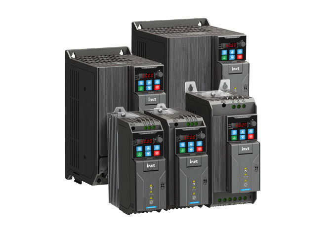
First steps with the INVT GD28
Ten steps from unboxing to the first motor run: connect, clarify STO, enter motor data, set start/stop and setpoint, adjust ramps. You only need digital inputs, Modbus and the braking resistor if your application uses them.
Disconnect all supplies and wait at least 5 minutes (manual, all GD28 models). Only then open the cover and touch the terminals.
Always connect the protective earth (PE) first. Never apply mains voltage to U, V, W.
STO is jumpered at the factory and therefore inactive. If you use STO as a safety function, you need a risk assessment and an acceptance test (step 2).
1Connect mains and motorRequired
Mains to L1, L2, L3 (S2 models: L, N), motor to U, V, W, PE to both earthing screws. On frame sizes A–C, the mains terminals are at the top and the motor terminals at the bottom; on D and E, everything is in one row at the bottom.
The wiring diagram shows the cross-sections, circuit breaker and fuse for your model. The table values in the manual are guide values and must not be undercut.
The manual recommends symmetrical shielded mains and motor cables. Above the motor cable length given in manual Tab. B-2 (e.g. 2.2 kW: 150 m shielded), an output reactor is required.
For EMC category C2, add an external mains filter. The matching filter type for your model is shown in the wiring diagram “Mains with EMC filter”.
Wrong rotation direction: P00.13 = 1 or swap two motor phases.
Show wiring “Mains and motor”Show wiring “Mains with EMC filter”
Source: gd28/10-klemmen, 10b-installation, 12-zubehoer-schutzorgane
2STO: factory jumper or safety circuitRequired
On delivery, +24V, STO1 and STO2 are jumpered. The inverter runs, but STO is not a safety function.
For STO, remove the jumpers and wire two NC contacts of a safety relay or emergency stop into the circuits +24V–STO1 and +24V–STO2. Both channels must switch together within 200 ms.
Parameter Value Meaning P08.55 0 After E40, a reset is required (factory default); 1 = message clears automatically Displays
Display Meaning E40 STO active: both channels open E41 / E42 Channel discrepancy channel 1 / channel 2 – only mains off/on resets E43 both channels faulty E44 FLASH CRC error of the STO code – replace the driver board If the jumpers are removed without a wired safety circuit, the inverter reports E40 and does not start.
STO does not replace an emergency stop and does not disconnect the supply. Ratings: SIL 3, PL e, category 3. Cable double-shielded, max. 25 m.
Carry out and document the acceptance test according to manual appendix F.8 at first commissioning and after every safety-relevant change.
Show wiring “STO (Safe Torque Off)”
Practise on the keypad: “Reset STO message E40”
Source: gd28/11-sto, 10-klemmen §9
3Enter motor data and motor auto-tuningRequired
The values are on the motor's rating plate. The parameters of group P02 can only be changed at standstill.
Parameter Value Meaning P02.00 0 Motor type: 0 = asynchronous motor (factory default), 1 = permanent magnet synchronous motor P02.01 Rating plate Rated power in kW P02.02 Rating plate Rated frequency, in Europe usually 50.00 Hz P02.03 Rating plate Rated speed in min⁻¹ P02.04 Rating plate Rated voltage in V P02.05 Rating plate Rated current in A P00.00 0, 1 or 2 Control mode: 2 = SVPWM/V/f (factory default), 0 or 1 = sensorless vector control (only after auto-tuning) Motor auto-tuning
P00.01 = 0 (start via the keypad).
Enter P02.01 to P02.05 from the rating plate.
Select P00.15: 1 = full rotating (uncouple the motor from the load), 2 = full static, 3 = partial static. Confirm with ENT/SHIFT; the display shows -TUN-.
Press RUN. The display counts the steps (TUN-1 …), RUN/TUNE flashes.
At -End-, auto-tuning is complete; the determined motor parameters are saved.
Practise on the keypad: “Enter motor data and run motor auto-tuning”
Source: gd28/01-basis, manual chap. 6.2.1
4Set the start/stop sourceRequired
P00.01 determines where the start command comes from. The digital inputs are set to PNP at the factory (NPN/PNP slide switch): the contact is between +24V and DIx.
Parameter Value Meaning P00.01 0 / 1 / 2 0 = keypad (factory default), 1 = terminals, 2 = communication P05.01 1 DI1 = forward (factory default) P05.02 2 DI2 = reverse – factory default is 4 = jog forward P07.04 0–3 Effect of the STOP/RST key with terminal or communication control (factory 0 = keypad only) DI3 is fault reset at the factory (P05.03 = 7).
LOCAL/REMOT shows the command source: off = keypad, flashing = terminals, on = communication.
Show wiring “Start/stop via switch”Show wiring “Start/stop from PLC (PNP)”
Practise on the keypad: “Start and stop the motor from the keypad”Practise on the keypad: “Switch the run command to terminals”
Source: gd28/01-basis, 02-io, 03-io-hmi
5Set the setpointRequired
Parameter Value Meaning P00.06 0 / 1 / 2 / 3 / 10 Frequency setpoint A: 0 = P00.10 (factory), 1 = AI1, 2 = AI2, 3 = AI3 (keypad potentiometer), 10 = Modbus P00.10 50.00 Hz Frequency setting via the keypad (factory) P00.03 50.00 Hz Maximum output frequency, reference for setpoints and ramps (only at standstill) P00.04 / P00.05 50.00 / 0.00 Hz Upper and lower limit of the running frequency P05.76 0x0 / 0x1 AI signal type: bit 0 = AI1, bit 1 = AI2, 1 = current AI1/AI2 slide switches and P05.76 must match, otherwise the analog setpoint will be wrong.
For 4–20 mA at AI1: switch to I, P05.76 = 0x1; in current mode, the lower limit P05.42 is set to 4.00 mA at the factory.
Show wiring “Setpoint via potentiometer”Show wiring “Setpoint 4–20 mA from PLC”
Practise on the keypad: “Set frequency setting P00.10 to 15.00 Hz”Practise on the keypad: “Setpoint via the potentiometer (AI3)”
Source: gd28/01-basis, 02-io, 10-klemmen §6
6Set acceleration and deceleration timeOptional
Parameter Value Meaning P00.11 model-dependent Acceleration time 1 from 0 Hz to P00.03 (0.0–3600.0 s) P00.12 model-dependent Deceleration time 1 from P00.03 to 0 Hz A deceleration time that is too short with a large flywheel mass leads to E8 (overvoltage during deceleration). Then extend the deceleration time or connect a braking resistor (step 9).
Practise on the keypad: “Set acceleration time P00.11 to 5.0 s”
Source: gd28/01-basis
7Assign digital inputs and relaysOptional
Factory defaults
Terminal Parameter Factory Meaning DI1 P05.01 1 Forward DI2 P05.02 4 Jog forward DI3 P05.03 7 Fault reset DI4 P05.04 0 no function (with switch PTC and 57: PTC thermistor) HDI1 P05.00 0 Pulse input; with 1 normal digital input RO1 P06.05 1 running; 5 = inverter in fault state Further functions: 2 = reverse, 3 = three-wire run control, 5 = jog reverse (function list 0–95 in the manual).
HDO1 is a pulse output at the factory; as a digital output P06.00 = 1.
PTC thermistor in the motor: connect to DI4 and COM, set slide switch DI4/PTC to PTC, P05.04 = 57. On overtemperature the inverter stops with E59.
Show wiring “Fault signal via relay”Show wiring “Motor temperature (PTC) at DI4”
Source: gd28/02-io
8Set up Modbus RTU or EthernetOptional
Parameter Value Meaning P00.01 2 Start command via communication P00.06 10 Frequency setpoint via Modbus/Modbus TCP (on the GD27 it would be 8) P14.00 1 Slave address (factory) P14.01 4 19200 bit/s (factory) P14.02 1 E, 8, 1 (factory) P14.04 0.0 s Timeout off (factory); otherwise fault E18 if telegrams stop arriving Control word 0x2000: 1 = forward, 5 = stop, 7 = fault reset. Frequency setpoint 0x2001 in 0.01 Hz.
Internal 120 Ω termination via the 485 slide switch: set to ON only at the two bus ends.
Ethernet (PROFINET, EtherCAT, EtherNet/IP, Modbus TCP) via the EC-TX149 card: protocol in P24.00, frequency setpoint P00.06 = 14 (or 10 for Modbus TCP).
Show wiring “Modbus RTU to PLC”
Source: gd28/04-modbus, 13-ec-tx149-kommunikation, 10-klemmen §10
9Connect a braking resistorOptional
The brake chopper is built into every GD28; only the resistor is external: between (+) and PB, never to (−).
Parameter Value Meaning P08.39 1 Enable dynamic braking – factory default 0 = off P08.40 700.0 V Switch-on threshold for 400 V models (220 V models: 380.0 V) Never go below the minimum resistance from manual Tab. E-6, otherwise the chopper will be destroyed. The wiring diagram shows the values for each model.
Without P08.39 = 1, the resistor stays cold; the inverter then extends the ramp via the overvoltage protection (P11.03).
Show wiring “Braking resistor”
Practise on the keypad: “Reset fault E8”
Source: gd28/06-schutz, 12-zubehoer-schutzorgane
10First runRequired
Group P17 provides the operating values (e.g. P17.04 output current, P17.11 DC link voltage), the fault memory P07.27 ff.
Practise on the keypad: “Start and stop the motor from the keypad”Practise on the keypad: “Read operating values (P17) and fault memory (P07)”
Source: gd28/01-basis, 08-monitor, 03-io-hmi
Revision 2.0 · 26.09.2026 · Source: INVT GD28 Manual V1.3 (03/2026), prepared in spstiger vfd-konfig (gd28/01-basis, 02-io, 03-io-hmi, 04-modbus, 06-schutz, 10-klemmen, 10b-installation, 11-sto, 12-zubehoer-schutzorgane). The manufacturer manual and applicable standards take precedence; installation and commissioning by a qualified electrician only.
Available in 30 days, delivery time 3 bis 5 Tage
Preis exkl. MwSt., zzgl. Versandkosten