


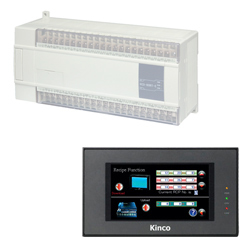
Kinco HMIs are an inexpensive visualization and operating option for Modbus devices. Modbus devices can be visualized and operated very easily with Kinco HMIs. Select your desired connection type to see how the HMI and Modbus PLC are connected to each other.
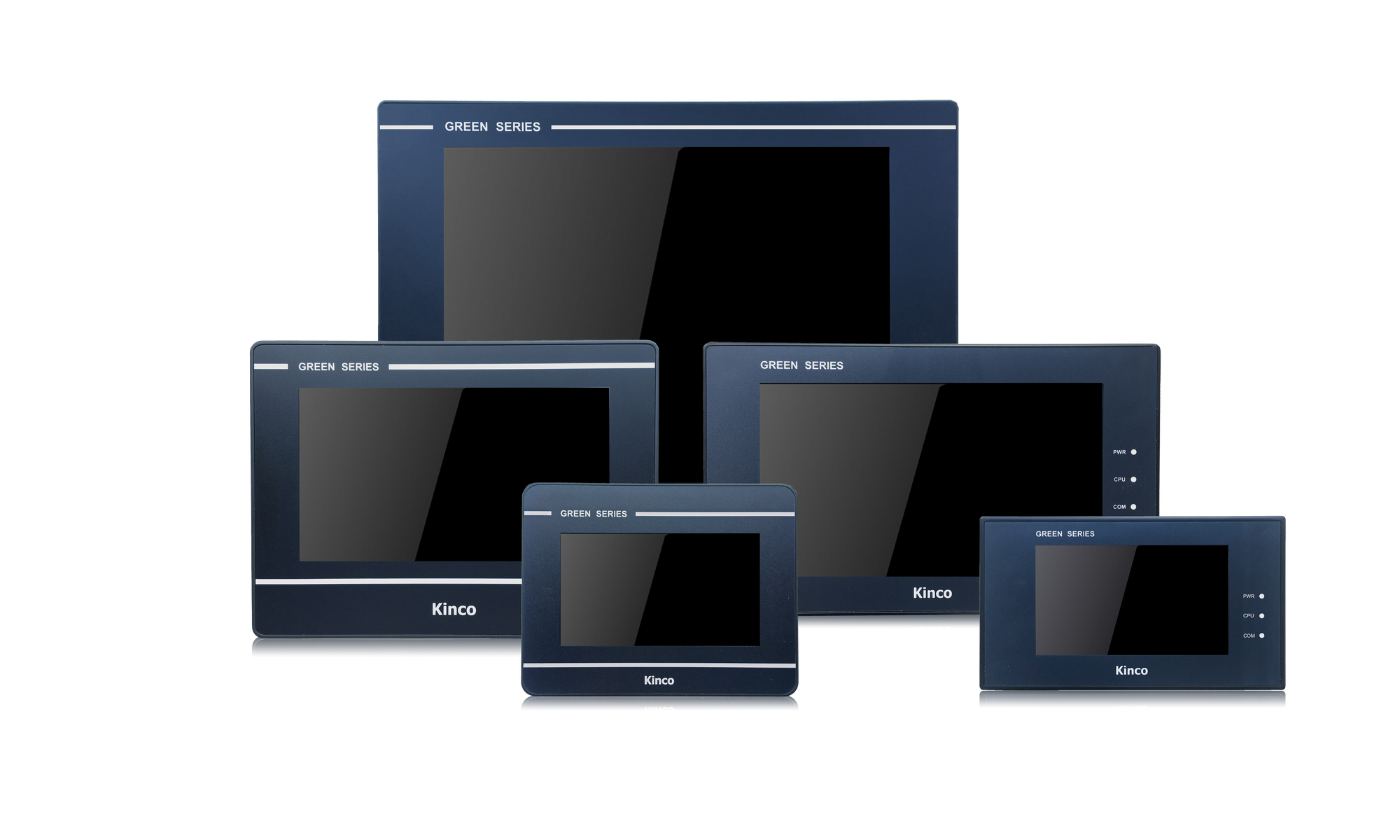
The programming software (German) for the Kinco HMI is completely free of charge. The programming software is available as a free download from the respective HMI. Below you will find an overview of all Kinco HMIs. Simply select the right size for your visualization project.
Select a connection type:
-
Modbus TCP, Modbus UDP (Ethernet)
-
Kinco HMI as Modbus TCP/UDP client (master)
- Connection
- Driver configuration in Kinco HMIware
- Addressing
Connection of the Modbus server (slave) participants via Ethernet
A Modbus TCP/UDP server (slave) can be easily connected to the Kinco HMI via Ethernet. You can connect the PLC either via a direct LAN connection or via a hub or switch. This allows you to visualize and operate several participants on the Kinco HMI via the LAN.
All Kinco HMIs in our online store have a standard RJ-45 Ethernet connection for this purpose.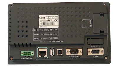 The Ethernet connection of a 7" Kinco MT4424TE HMI
Driver configuration for Modbus TCP via Ethernet in the Kinco HMIware
The appropriate driver in the Kinco HMIware for connecting Modbus servers (slaves) via Ethernet is the Modbus TCP slave driver.
Alternatively, the Modbus UDP slave driver can also be used if the end device also supports Modbus UDP.All Kinco HMIs with an Ethernet connection can communicate with Modbus devices via the Ethernet module. To do this, a project must be created accordingly in the Kinco HMIware, the communication configured and the project transferred to the HMI. The configuration is carried out in the following steps.
- Create a new project in the Kinco HMIware or open an existing project
- Drag the HMI used in the HMI tab into the project
- Under PLC, drag the Modbus TCP slave into the project
- Open the configuration of the LAN by double-clicking on the PLC, then "Network Device Settings"
- Add the PLC under "Add" and configure the IP of the PLC
- Add the HMI under "Add" and configure the IP of the HMI
- Close all open windows with Ok
- Create screens and objects that are linked to variables in the PLC (more on this under Addressing)
- Compile the project and transfer it to the HMI via download
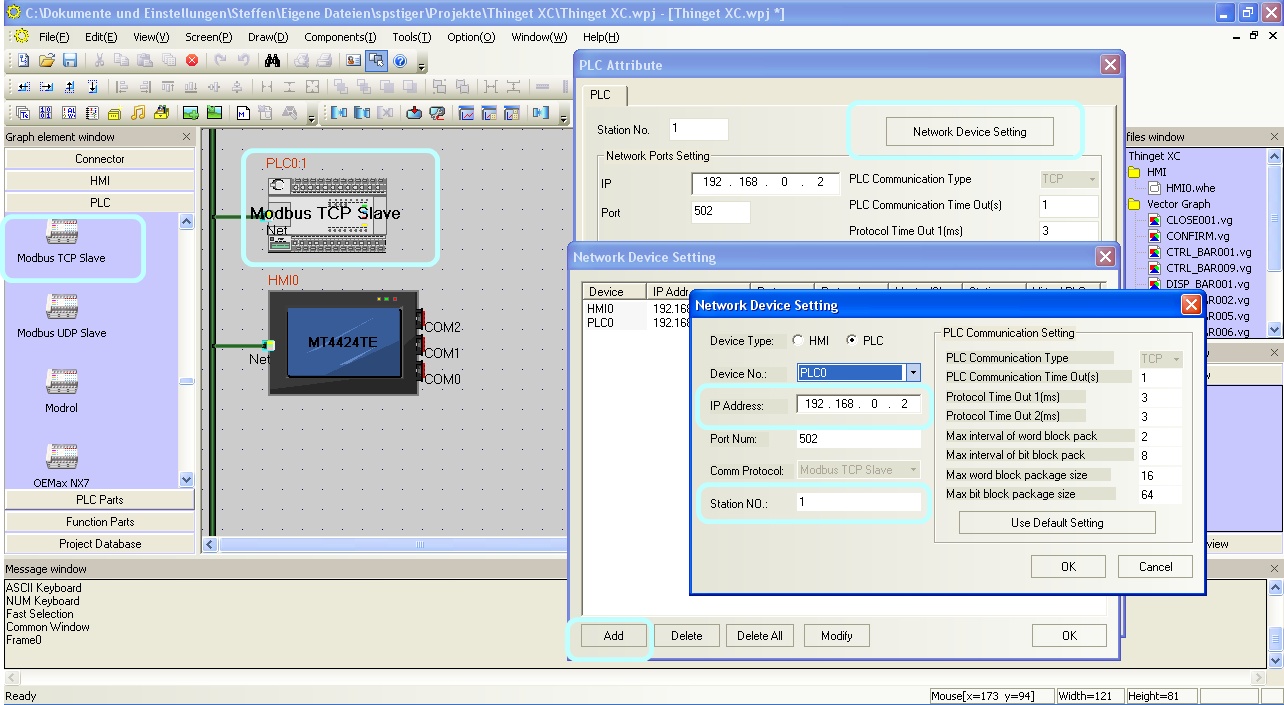 Configure the communication between Kinco HMI and a Modbus TCP server (slave) via Ethernet in the Kinco HMIware. Make sure that the station number is correct.
The full version of the programming software for the Kinco HMI can be downloaded here
Kinco HMIware 2.0 (248 MB)
Addressing the Modbus variables
Kinco HMI elements
Kinco HMIware provides a wide range of elements for visualizing and changing PLC data. These include, for example, switches, lamps, input fields and much more. These elements can be easily linked to variables in the PLC. For Modbus, all important Modbus areas are available via the Ethernet connection. The exact list of all addressable areas can be found below.
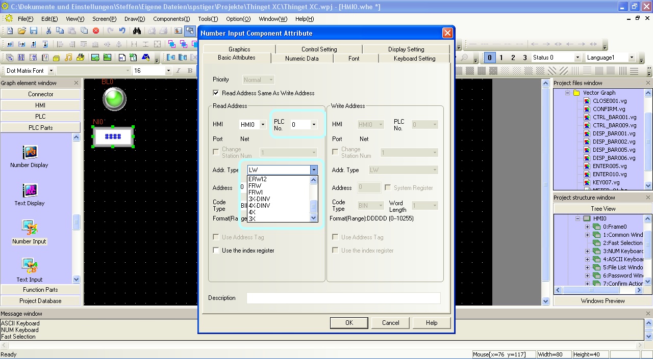 Selection of a variable in an HMI element in the Kinco HMIware
Address overview of the drivers
The Modbus addressing in Kinco HMIware is as follows:
Note: In the Kinco HMIware, the Modbus addresses start at 1, in many Modbus devices at 0. Therefore, there is often an offset of one position in the addressing. In the Kinco HMIware, you should then add +1 to the address.Address rangeModbus addressVariables of the
Modbus subscriberBits Readable and writable bit addresses 0X 0-65535 refer to the manual for your Modbus device,
to find out which address ranges are referenced hereRead-only bit addresses 1X 0-65535 refer to the manual for your Modbus device,
to find out which address ranges are referenced hereRead-only registers, addressed bit by bit 3X_Bit 0.00-65535.15 refer to the manual for your Modbus device,
to find out which address ranges are referenced hereWrite and readable registers, addressed bit by bit 4X_Bit 0.00-65535.15 refer to the manual for your Modbus device,
to find out which address ranges are referenced hereRegisters 16-bit read-only registers 3X 0-65535 refer to the manual of your Modbus device,
which address ranges are referenced hereRead and write registers 16-bit 4X 0-65535 refer to the manual for your Modbus device,
to find out which address ranges are referenced here
Further information on programming the Kinco HMI can be found in our online course
Kinco HMIware online course
-
Kinco HMI as Modbus TCP/UDP server (slave)
- Connection
- Driver configuration in Kinco HMIware
- Addressing
Connection of the Modbus client (master) participants via Ethernet
Kinco HMIs can also be operated as Modbus TCP servers (slaves). In this case, another participant (client or master) accesses the data in the HMI and writes and reads the internal variables there. These internal variables can then be used for visualization and operation on the HMI. You can connect the CLient (master) either via a direct LAN connection or via a hub or switch.
All Kinco HMIs in our online store have a standard RJ-45 Ethernet connection for this purpose.
The Ethernet connection of a 7" Kinco MT4424TE HMIDriver configuration for the HMI as a Modbus TCP server (slave) via Ethernet in the Kinco HMIware
To operate the HMI as a Modbus TCP or Modbus UDP server (slave), you do not need to configure any external devices in the Kinco HMIware. It is sufficient to configure the communication protocol of the network in the Kinco HMI. You do this in the following steps:- Create a new project in the Kinco HMIware or open an existing project
- Drag the HMI used in the HMI tab into the project
- Open the LAN configuration by double-clicking on the HMI, then "Network Device Settings"
- Add the HMI under "Add" and configure the IP and station number of the HMI
- Under "Comm Protocol", select Modbus TCP Slave or Modbus UPD Slave
- Close all open windows with Ok
- Create screens and objects that are linked to variables in the PLC (more on this under Addressing)
- Compile the project and transfer it to the HMI via download
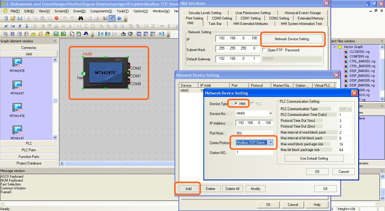 Configure the communication between Kinco HMI and a Modbus TCP server (slave) via Ethernet in the Kinco HMIware. Make sure you have the correct station number so that your client can access the HMI.
The full version of the programming software for the Kinco HMI can be downloaded here
Kinco HMIware 2.0 (248 MB)
Addressing the internal variables
Kinco HMI elements
Kinco HMIware provides a wide range of elements for visualizing and changing PLC data. These include, for example, switches, lamps, input fields and much more.
For operation as a Modbus slave, these elements are linked to internal variables of the HMI. The Modbus masters can then access these variables themselves and read or write them.
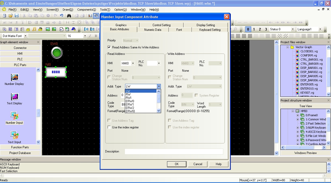 Selection of an internal variable in an HMI element in the Kinco HMIware
Address overview of the drivers
The Modbus addressing of the internal variables in Kinco HMIware is as follows:
Address rangeModbus addressInternal
of the Kin bits Read and writeable bit addresses 0X 0-9999 LB 0-9999 Register Readable and writable registers 16-bit 4X 0-9999 LW 0-9999
Further information on programming the Kinco HMI can be found in our online course
Kinco HMIware online course
-
-
Modbus RTU (serial)
-
Kinco HMI as Modbus RTU master
- Connection
- Driver configuration in Kinco HMIware
- Addressing
Serial connection of Modbus devices via RS-232 or RS-485
You can easily connect serial Modbus devices to the Kinco HMI via a serial interface. You can often connect them directly to the programming cable of the Modbus device. The small 4'' Kinco HMI has one serial connection, devices from 6'' have at least two serial interfaces.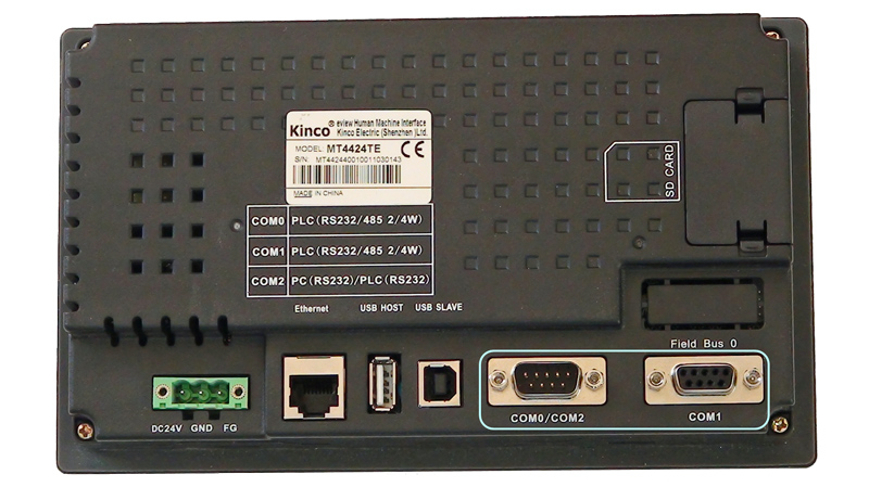 The serial ports of a 7" Kinco MT4424TE HMI support both RS-232 and RS-485 communication
RS-232
RS-232 is a serial communication protocol for a point-to-point direct connection. A Modbus device can be connected directly to the HMI via RS-232. All physical ports on the Kinco HMI support RS-232 communication. The physical connection COM 0 has an additional RS-232 connection (COM 2) on pins 7 (Rx) and 8 (Tx). A special serial cable is required to connect this to the Thinget PLC.
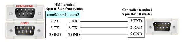 Pin assignment of the RS-232 connection for connecting the Kinco HMI to a Modbus subscriber
RS-485
RS-485 is a protocol for serial communication with several participants. You can use RS-485 to allow several devices to communicate with the HMI via a single serial connection.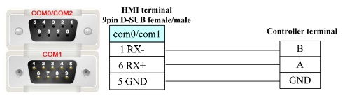 Pin assignment of the RS-485 connection for connecting the Kinco HMI with Modbus participants
Driver for Modbus devices via a serial connection in the Kinco HMIware
The appropriate driver in the Kinco HMIware for connecting Modbus devices via the serial interface is the Modbus RTU driver.
Alternatively, you can also use the Modbus ASCII driver if your end device only supports Modbus ASCII.All Kinco HMIs can communicate with Modbus devices via the serial interface. To do this, a project must be created accordingly in the Kinco HMIware, the communication configured and the project transferred to the HMI. The graphical configuration is carried out in the following steps.
- Create a new project in the Kinco HMIware or open an existing project
- Drag the HMI used in the HMI tab into the project
- Under PLC, drag the "Modbus RTU" device into the project
- Now open the "Connector" menu and use "Serial Port" to drag a serial connection into the project
- Connect the serial connection to COM 0 or COM 1 on the HMI (special cables are required for COM 2)
- Connect the serial connection to COM 0 on the PLC
- Important: Double-click on the PLC to configure the Station Number
- Double-click on the HMI to configure the corresponding serial COM port
- Compile the project and transfer it to the HMI via download
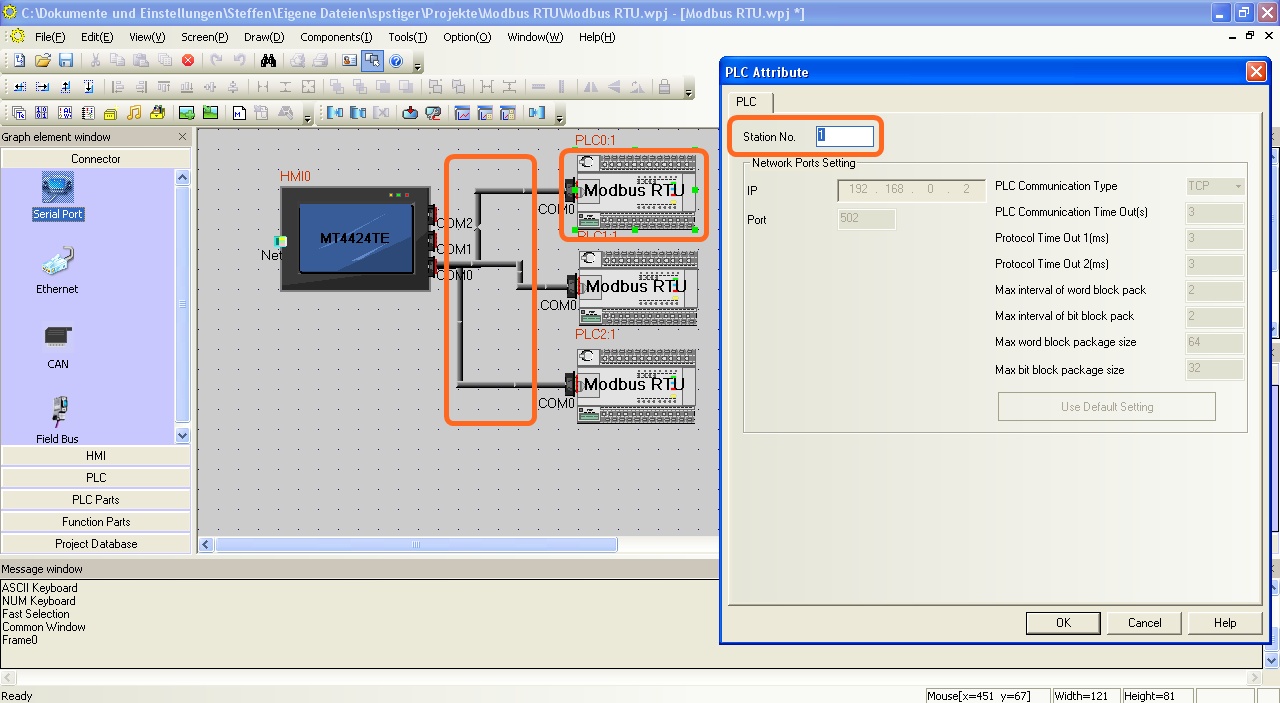 Configure the communication between the Kinco HMI and several Modbus devices via the serial interface in the Kinco HMIware - the configuration of the Station Number is important.
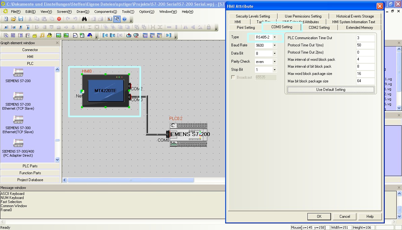 The configuration of the serial interface of the Kinco HMI can be accessed by double-clicking on the HMI. The type of communication (RS-232, RS-485-2, i.e. two-wire or RS-485-4, i.e. four-wire) is configured here. You can also configure the baud rate and other parameters here.
The full version of the programming software for the Kinco HMI can be downloaded here
Kinco HMIware 2.0 (248 MB)
Addressing the Modbus variables
Kinco HMI elements
Kinco HMIware provides a wide range of elements for visualizing and changing PLC data. These include, for example, switches, lamps, input fields and much more. These elements can be easily linked to variables in the PLC. For Modbus, all important Modbus areas are available via the serial connection. The exact list of all addressable areas can be found below.
Selection of a variable in an HMI element in the Kinco HMIware
Address overview of the drivers
The Modbus addressing in Kinco HMIware is as follows:
Note: In the Kinco HMIware, the Modbus addresses start at 1, in many Modbus devices at 0. Therefore, there is often an offset of one position in the addressing. In the Kinco HMIware, you should then add +1 to the address.Address rangeModbus addressVariables of the
Modbus subscriberBits Readable and writable bit addresses 0X 0-65535 refer to the manual for your Modbus device,
to find out which address ranges are referenced hereRead-only bit addresses 1X 0-65535 refer to the manual for your Modbus device,
to find out which address ranges are referenced hereRead-only registers, addressed bit by bit 3X_Bit 0.00-65535.15 refer to the manual for your Modbus device,
to find out which address ranges are referenced hereWrite and readable registers, addressed bit by bit 4X_Bit 0.00-65535.15 refer to the manual for your Modbus device,
to find out which address ranges are referenced hereRegisters 16-bit read-only registers 3X 0-65535 refer to the manual of your Modbus device,
which address ranges are referenced hereRead and write registers 16-bit 4X 0-65535 refer to the manual for your Modbus device,
to find out which address ranges are referenced here
Further information on programming the Kinco HMI can be found in our online course
Kinco HMIware online course
-
Kinco HMI as a Modbus RTU slave
- Connection
- Driver configuration in Kinco HMIware
- Addressing
Serial connection of Modbus master devices via RS-232 or RS-485
You can easily connect serial Modbus master devices to the Kinco HMI via a serial interface. The small 4'' Kinco HMI has one serial port, devices from 6'' have at least two serial ports.
The serial ports of a 7" Kinco MT4424TE HMI support both RS-232 and RS-485 communicationRS-232
RS-232 is a serial communication protocol for a point-to-point direct connection. RS-232 allows a Modbus master to connect directly to the HMI and read or write data to it. All physical ports on the Kinco HMI support RS-232 communication. The physical port COM 0 has an additional RS-232 connection (COM 2) on pins 7 (Rx) and 8 (Tx). A special serial cable is required to connect this to the Thinget PLC.
Pin assignment of the RS-232 connection for connecting the Kinco HMI to a Modbus subscriber
RS-485
RS-485 is a protocol for serial communication with multiple participants. RS-485 allows your Modbus master to communicate with multiple devices, including one or more Kinco HMIs, on a single serial port.
Pin assignment of the RS-485 connection for connecting the Kinco HMI with Modbus participants
Driver for Modbus master via a serial connection in the Kinco HMIware
The appropriate driver in the Kinco HMIware for connecting Modbus masters via the serial interface is the Modbus RTU slave driver.
This is somewhat confusing, as the external participant is actually the Modbus master and the HMI is actually the slave. The configuration of the serial port with the Device ID in the Kinco HMI is particularly important.All Kinco HMIs can communicate with Modbus masters via a serial interface. To do this, a project must be created accordingly in the Kinco HMIware, the communication configured and the project transferred to the HMI. The graphical configuration is carried out in the following steps.
- Create a new project in the Kinco HMIware or open an existing project
- Drag the HMI used in the HMI tab into the project
- Under PLC, drag the "Modbus RTU Slave" device into the project
- Now open the "Connector" menu and use "Serial Port" to drag a serial connection into the project
- Connect the serial connection to COM 0 or COM 1 on the HMI (special cables are required for COM 2)
- Connect the serial connection to COM 0 on the PLC
- Important: Double-click on the HMI to configure the serial connection and the device number. The HMI can be accessed by the Modbus master under this device number.
- Compile the project and transfer it to the HMI via download
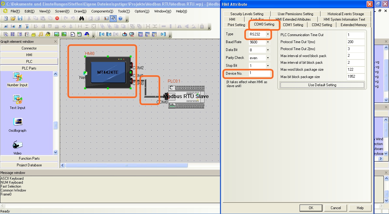 The configuration of the communication between Kinco HMI and an external Modbus master via the serial interface in the Kinco HMIware - the configuration of the device number (station number) is importantThe full version of the programming software for the Kinco HMI can be downloaded here
Kinco HMIware 2.0 (248 MB)
Addressing the internal variables via Modbus
Kinco HMI elements
Kinco HMIware provides a wide range of elements for visualizing and changing PLC data. These include, for example, switches, lamps, input fields and much more.
For operation as a Modbus slave, these elements are linked to internal variables of the HMI. The Modbus masters can then access these variables themselves and read or write them.
Selection of an internal variable in an HMI element in the Kinco HMIware
Address overview of the drivers
The Modbus addressing of the internal variables in Kinco HMIware is as follows:
Address rangeModbus addressInternal
of the Kin bits Readable and writable bit addresses 0X 0-9999 LB 0-9999 Register Readable and writable registers 16-bit 4X 0-9999 LW 0-9999
Further information on programming the Kinco HMI can be found in our online course
Kinco HMIware online course
-