


Solidot EC4 – Support, Wiring Diagram & Commissioning
Everything for your Solidot EC4 after purchase – for all 18 models in the Shop: digital with 16 or 32 channels, relay and analog with four or eight channels:
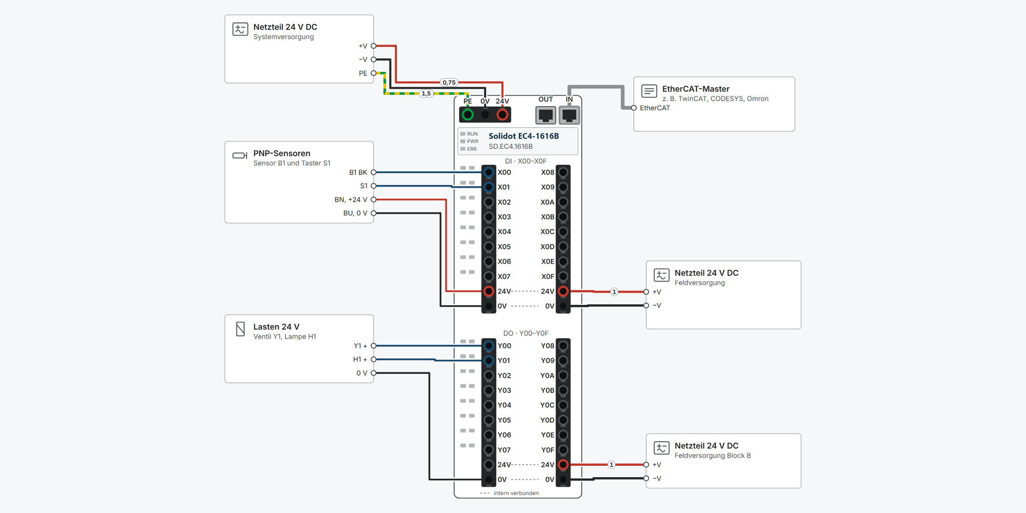
Interactive wiring diagram: system and field supply, PNP sensors, loads, relays, 2-, 3- and 4-wire transmitters, analog output to a drive, EtherCAT to the master and further devices in the line, with cable cross-sections and parameters
EtherCAT: ESI file, adding it in TwinCAT, CODESYS and Sysmac Studio, objects and parameters for your model
First steps: commissioning in ten steps, from the DIN rail to the first signal in the EtherCAT master
Dimensions & mounting: outside dimensions, DIN rail, minimum clearances, connectors and cross-sections
Downloads: user manual, ESI files, 2D and 3D drawings and EPLAN macros
Free support from spstiger if you get stuck
Interactive wiring diagram
Tap a terminal or wire in the drawing to see details.
Terminal overview EC4
| Terminal | Group | mm² | Function |
|---|---|---|---|
| PE | Supply | 0.3–1.5 | Earth. Connect PE securely to earth (manual ch. 6.2). |
| 0V | Supply | 0.3–1.5 | 0 V of the system supply. |
| 24V | Supply | 0.3–1.5 | System supply +24 V DC (18–36 V) for the module electronics, ≤ 500 mA (manual ch. 3.5). Keep it separate from the field supply of the inputs and outputs. |
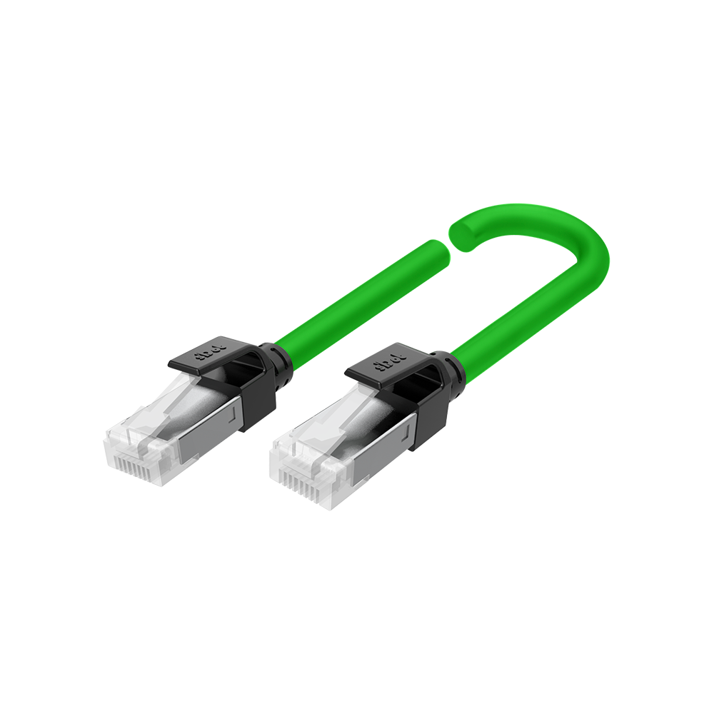
| OUT | EtherCAT | – | EtherCAT output: cable to the IN of the next device; leave free if the module is the last one in the line. 100 Mbit/s, RJ45, shielded cable Cat. 5 or higher (STP), max. 100 m between two devices. LED on the socket: green = link, yellow flashing = data exchange. On the top, OUT is directly next to the supply connector, IN is on the outside. |
| IN | EtherCAT | – | EtherCAT input: cable from the master or from the OUT of the previous device. 100 Mbit/s, RJ45, shielded cable Cat. 5 or higher (STP), max. 100 m between two devices. LED on the socket: green = link, yellow flashing = data exchange. On the top, OUT is directly next to the supply connector, IN is on the outside. |
| X00 | Block A 1–10 | 0.3–1 | Digital input X00, PNP: “1” at 15–30 V, “0” at −3…+3 V referred to 0 V, 4 mA, filter 3 ms, optically isolated. EtherCAT: object 0x6000:01 “Channel In1” (BOOL). |
| X01 | Block A 1–10 | 0.3–1 | Digital input X01, PNP: “1” at 15–30 V, “0” at −3…+3 V referred to 0 V, 4 mA, filter 3 ms, optically isolated. EtherCAT: object 0x6000:02 “Channel In2” (BOOL). |
| X02 | Block A 1–10 | 0.3–1 | Digital input X02, PNP: “1” at 15–30 V, “0” at −3…+3 V referred to 0 V, 4 mA, filter 3 ms, optically isolated. EtherCAT: object 0x6000:03 “Channel In3” (BOOL). |
| X03 | Block A 1–10 | 0.3–1 | Digital input X03, PNP: “1” at 15–30 V, “0” at −3…+3 V referred to 0 V, 4 mA, filter 3 ms, optically isolated. EtherCAT: object 0x6000:04 “Channel In4” (BOOL). |
| X04 | Block A 1–10 | 0.3–1 | Digital input X04, PNP: “1” at 15–30 V, “0” at −3…+3 V referred to 0 V, 4 mA, filter 3 ms, optically isolated. EtherCAT: object 0x6000:05 “Channel In5” (BOOL). |
| X05 | Block A 1–10 | 0.3–1 | Digital input X05, PNP: “1” at 15–30 V, “0” at −3…+3 V referred to 0 V, 4 mA, filter 3 ms, optically isolated. EtherCAT: object 0x6000:06 “Channel In6” (BOOL). |
| X06 | Block A 1–10 | 0.3–1 | Digital input X06, PNP: “1” at 15–30 V, “0” at −3…+3 V referred to 0 V, 4 mA, filter 3 ms, optically isolated. EtherCAT: object 0x6000:07 “Channel In7” (BOOL). |
| X07 | Block A 1–10 | 0.3–1 | Digital input X07, PNP: “1” at 15–30 V, “0” at −3…+3 V referred to 0 V, 4 mA, filter 3 ms, optically isolated. EtherCAT: object 0x6000:08 “Channel In8” (BOOL). |
| 24V | Block A 1–10 | 0.3–1 | Field supply +24 V DC of block DI. Terminals 9 and 19 are connected internally. |
| 0V | Block A 1–10 | 0.3–1 | 0 V of the field supply. Terminals 10 and 20 are connected internally. |
| X08 | Block A 11–20 | 0.3–1 | Digital input X08, PNP: “1” at 15–30 V, “0” at −3…+3 V referred to 0 V, 4 mA, filter 3 ms, optically isolated. EtherCAT: object 0x6000:09 “Channel In9” (BOOL). |
| X09 | Block A 11–20 | 0.3–1 | Digital input X09, PNP: “1” at 15–30 V, “0” at −3…+3 V referred to 0 V, 4 mA, filter 3 ms, optically isolated. EtherCAT: object 0x6000:0A “Channel In10” (BOOL). |
| X0A | Block A 11–20 | 0.3–1 | Digital input X0A, PNP: “1” at 15–30 V, “0” at −3…+3 V referred to 0 V, 4 mA, filter 3 ms, optically isolated. EtherCAT: object 0x6000:0B “Channel In11” (BOOL). |
| X0B | Block A 11–20 | 0.3–1 | Digital input X0B, PNP: “1” at 15–30 V, “0” at −3…+3 V referred to 0 V, 4 mA, filter 3 ms, optically isolated. EtherCAT: object 0x6000:0C “Channel In12” (BOOL). |
| X0C | Block A 11–20 | 0.3–1 | Digital input X0C, PNP: “1” at 15–30 V, “0” at −3…+3 V referred to 0 V, 4 mA, filter 3 ms, optically isolated. EtherCAT: object 0x6000:0D “Channel In13” (BOOL). |
| X0D | Block A 11–20 | 0.3–1 | Digital input X0D, PNP: “1” at 15–30 V, “0” at −3…+3 V referred to 0 V, 4 mA, filter 3 ms, optically isolated. EtherCAT: object 0x6000:0E “Channel In14” (BOOL). |
| X0E | Block A 11–20 | 0.3–1 | Digital input X0E, PNP: “1” at 15–30 V, “0” at −3…+3 V referred to 0 V, 4 mA, filter 3 ms, optically isolated. EtherCAT: object 0x6000:0F “Channel In15” (BOOL). |
| X0F | Block A 11–20 | 0.3–1 | Digital input X0F, PNP: “1” at 15–30 V, “0” at −3…+3 V referred to 0 V, 4 mA, filter 3 ms, optically isolated. EtherCAT: object 0x6000:10 “Channel In16” (BOOL). |
| 24V | Block A 11–20 | 0.3–1 | Field supply +24 V DC of block DI. Terminals 9 and 19 are connected internally. |
| 0V | Block A 11–20 | 0.3–1 | 0 V of the field supply. Terminals 10 and 20 are connected internally. |
| Y00 | Block B 1–10 | 0.3–1 | Digital output Y00, PNP: switches +24 V to the load, max. 500 mA, resistive and inductive loads, protected against overvoltage and overcurrent. EtherCAT: object 0x7000:01 “Channel Out1” (BOOL). |
| Y01 | Block B 1–10 | 0.3–1 | Digital output Y01, PNP: switches +24 V to the load, max. 500 mA, resistive and inductive loads, protected against overvoltage and overcurrent. EtherCAT: object 0x7000:02 “Channel Out2” (BOOL). |
| Y02 | Block B 1–10 | 0.3–1 | Digital output Y02, PNP: switches +24 V to the load, max. 500 mA, resistive and inductive loads, protected against overvoltage and overcurrent. EtherCAT: object 0x7000:03 “Channel Out3” (BOOL). |
| Y03 | Block B 1–10 | 0.3–1 | Digital output Y03, PNP: switches +24 V to the load, max. 500 mA, resistive and inductive loads, protected against overvoltage and overcurrent. EtherCAT: object 0x7000:04 “Channel Out4” (BOOL). |
| Y04 | Block B 1–10 | 0.3–1 | Digital output Y04, PNP: switches +24 V to the load, max. 500 mA, resistive and inductive loads, protected against overvoltage and overcurrent. EtherCAT: object 0x7000:05 “Channel Out5” (BOOL). |
| Y05 | Block B 1–10 | 0.3–1 | Digital output Y05, PNP: switches +24 V to the load, max. 500 mA, resistive and inductive loads, protected against overvoltage and overcurrent. EtherCAT: object 0x7000:06 “Channel Out6” (BOOL). |
| Y06 | Block B 1–10 | 0.3–1 | Digital output Y06, PNP: switches +24 V to the load, max. 500 mA, resistive and inductive loads, protected against overvoltage and overcurrent. EtherCAT: object 0x7000:07 “Channel Out7” (BOOL). |
| Y07 | Block B 1–10 | 0.3–1 | Digital output Y07, PNP: switches +24 V to the load, max. 500 mA, resistive and inductive loads, protected against overvoltage and overcurrent. EtherCAT: object 0x7000:08 “Channel Out8” (BOOL). |
| 24V | Block B 1–10 | 0.3–1 | Field supply +24 V DC of block DO. Terminals 9 and 19 are connected internally. |
| 0V | Block B 1–10 | 0.3–1 | 0 V of the field supply. Terminals 10 and 20 are connected internally. |
| Y08 | Block B 11–20 | 0.3–1 | Digital output Y08, PNP: switches +24 V to the load, max. 500 mA, resistive and inductive loads, protected against overvoltage and overcurrent. EtherCAT: object 0x7000:09 “Channel Out9” (BOOL). |
| Y09 | Block B 11–20 | 0.3–1 | Digital output Y09, PNP: switches +24 V to the load, max. 500 mA, resistive and inductive loads, protected against overvoltage and overcurrent. EtherCAT: object 0x7000:0A “Channel Out10” (BOOL). |
| Y0A | Block B 11–20 | 0.3–1 | Digital output Y0A, PNP: switches +24 V to the load, max. 500 mA, resistive and inductive loads, protected against overvoltage and overcurrent. EtherCAT: object 0x7000:0B “Channel Out11” (BOOL). |
| Y0B | Block B 11–20 | 0.3–1 | Digital output Y0B, PNP: switches +24 V to the load, max. 500 mA, resistive and inductive loads, protected against overvoltage and overcurrent. EtherCAT: object 0x7000:0C “Channel Out12” (BOOL). |
| Y0C | Block B 11–20 | 0.3–1 | Digital output Y0C, PNP: switches +24 V to the load, max. 500 mA, resistive and inductive loads, protected against overvoltage and overcurrent. EtherCAT: object 0x7000:0D “Channel Out13” (BOOL). |
| Y0D | Block B 11–20 | 0.3–1 | Digital output Y0D, PNP: switches +24 V to the load, max. 500 mA, resistive and inductive loads, protected against overvoltage and overcurrent. EtherCAT: object 0x7000:0E “Channel Out14” (BOOL). |
| Y0E | Block B 11–20 | 0.3–1 | Digital output Y0E, PNP: switches +24 V to the load, max. 500 mA, resistive and inductive loads, protected against overvoltage and overcurrent. EtherCAT: object 0x7000:0F “Channel Out15” (BOOL). |
| Y0F | Block B 11–20 | 0.3–1 | Digital output Y0F, PNP: switches +24 V to the load, max. 500 mA, resistive and inductive loads, protected against overvoltage and overcurrent. EtherCAT: object 0x7000:10 “Channel Out16” (BOOL). |
| 24V | Block B 11–20 | 0.3–1 | Field supply +24 V DC of block DO. Terminals 9 and 19 are connected internally. |
| 0V | Block B 11–20 | 0.3–1 | 0 V of the field supply. Terminals 10 and 20 are connected internally. |
| LED | – | – | System indicators RUN, PWR and ERR on the front, one LED each on the IN and OUT sockets and one green LED per channel next to the terminal. |
| CHLED | – | – | One green LED per channel to the left of the terminals, level with the terminal row; with two LEDs per row, the left one is for terminals 1–8, the right one for 11–18. The drawing shows an example: green = on, grey = off. |
* Clamping range not stated in the manual, derived.
EtherCAT: ESI file, integration and process data
This is how you integrate the EC4 into your EtherCAT master: install the ESI file, connect the module to IN, scan. You do not need an IP address or a device name. Below are all channels of your model with their object, plus the startup parameters.
At a glance
- ESI file
- EcatTerminal-EC4_V4.04_BOOL.xml
- Vendor ID
- 0x00884443
- Address
- automatic (position in the line)
- Transmission
- 100 Mbit/s, 2 × RJ45 (IN, OUT)
- Tested in the manual
- TwinCAT 3, CODESYS V3.5, Omron Sysmac Studio
- One ESI file for all EC4 models. During the scan the master recognizes the model by its product code.
- Cable from the master to IN, the next device to OUT.
Which ESI file?
The ZIP “EC4-XML V1.2” under Downloads contains the current file EcatTerminal-EC4_V4.04_BOOL.xml: each channel is a separate BOOL (Channel In1, Channel Out1 …). The manual still gives older file names (“Solidot EC4_V1.0.2.xml” or “V1.1.7”) – use the file from the ZIP.
The subfolder contains two V4.02 versions in which the digital channels are transferred as a byte (USINT) or word (UINT). You only need them if your controller cannot map single bits. Install only one of the files in the project.
For some analog models the ESI also contains types with “V1” (e.g. EC4-A80V1) without range setting. The manual does not explain them; during the scan the master selects the type that the module reports.
Adding it to your master
TwinCAT 3
- Copy the ESI file to C:\TwinCAT\3.1\Config\Io\EtherCAT and restart TwinCAT.
- Start TwinCAT XAE and create a “New TwinCAT Project”.
- Right-click I/O → Devices → Scan, select the network card connected to the module, confirm “Scan for boxes” with Yes and “Activate Free Run” with Yes.
- The module appears as a box; the “Online” tab shows OP, and RUN on the module lights steadily.
- Parameters: select the module → Startup tab → New → select object 0x8000:xx and enter the value. Then reload the configuration and the program.
CODESYS V3.5
- Tools → Device Repository → Install → select the ESI file; the message “Device … installed to device repository” confirms the installation.
- Add an “EtherCAT Master” to the controller (Fieldbuses → EtherCAT → Master).
- In the master, click “Browse” and select the network card for the EtherCAT line.
- Before the first scan, select the controller and install the device (manual chap. 7.2.2, step 5), then right-click Master → Scan for Devices and copy the modules found into the project.
- Under “EtherCAT I/O Mapping”, assign variables and select “Enabled 1” for updating, log in again and start.
Omron Sysmac Studio
- Configurations and Setup → EtherCAT → right-click Master → Display ESI Library → Install (File) → select the ESI file.
- In the Toolbox, expand “Nanjing Solidot Electronic Technology Co., Ltd.” and insert the module by double-clicking.
- Controller → Communication Setup: “Ethernet connection via a hub”, enter the IP address of the controller, “Ethernet Communications Test”.
- Go online, right-click Master → Write Slave Node Address, enter the node address, Write – then switch the module off and on again.
- Controller → Transfer → To Controller, then power-cycle the controller and the module.
- Parameters: offline, select the module → “Edit Setting Parameters” (with older controller firmware via EC_CoESDOWrite/EC_CoESDORead). I/O Map for monitoring and forcing.
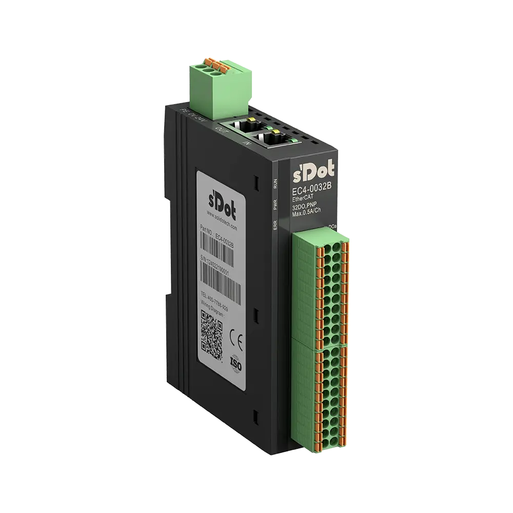
EC4-1600B · 16 DI PNP
| ESI type | Product code | Inputs | Outputs |
|---|---|---|---|
| EC4-1600B | 0x0041600B | 16 × BOOL | — |
Digital inputs X00–X0F
| Terminal | Signal | Object | Name in the ESI |
|---|---|---|---|
| 1 | X00 | 0x6000:01 | Channel In1 |
| 2 | X01 | 0x6000:02 | Channel In2 |
| 3 | X02 | 0x6000:03 | Channel In3 |
| 4 | X03 | 0x6000:04 | Channel In4 |
| 5 | X04 | 0x6000:05 | Channel In5 |
| 6 | X05 | 0x6000:06 | Channel In6 |
| 7 | X06 | 0x6000:07 | Channel In7 |
| 8 | X07 | 0x6000:08 | Channel In8 |
| 11 | X08 | 0x6000:09 | Channel In9 |
| 12 | X09 | 0x6000:0A | Channel In10 |
| 13 | X0A | 0x6000:0B | Channel In11 |
| 14 | X0B | 0x6000:0C | Channel In12 |
| 15 | X0C | 0x6000:0D | Channel In13 |
| 16 | X0D | 0x6000:0E | Channel In14 |
| 17 | X0E | 0x6000:0F | Channel In15 |
| 18 | X0F | 0x6000:10 | Channel In16 |
Show wiring “PNP sensors on DI”
No startup parameters: the input filter is fixed at 3 ms.
EC4-0016B · 16 DO PNP 0.5 A
| ESI type | Product code | Inputs | Outputs |
|---|---|---|---|
| EC4-0016B(W) | 0x0040016B | — | 16 × BOOL |
Digital outputs Y00–Y0F
| Terminal | Signal | Object | Name in the ESI |
|---|---|---|---|
| 1 | Y00 | 0x7000:01 | Channel Out1 |
| 2 | Y01 | 0x7000:02 | Channel Out2 |
| 3 | Y02 | 0x7000:03 | Channel Out3 |
| 4 | Y03 | 0x7000:04 | Channel Out4 |
| 5 | Y04 | 0x7000:05 | Channel Out5 |
| 6 | Y05 | 0x7000:06 | Channel Out6 |
| 7 | Y06 | 0x7000:07 | Channel Out7 |
| 8 | Y07 | 0x7000:08 | Channel Out8 |
| 11 | Y08 | 0x7000:09 | Channel Out9 |
| 12 | Y09 | 0x7000:0A | Channel Out10 |
| 13 | Y0A | 0x7000:0B | Channel Out11 |
| 14 | Y0B | 0x7000:0C | Channel Out12 |
| 15 | Y0C | 0x7000:0D | Channel Out13 |
| 16 | Y0D | 0x7000:0E | Channel Out14 |
| 17 | Y0E | 0x7000:0F | Channel Out15 |
| 18 | Y0F | 0x7000:10 | Channel Out16 |
Show wiring “Valve and lamp on DO”
Startup parameters (object 0x8000)
| Object | Name in the ESI | Default | Meaning |
|---|---|---|---|
| 0x8000:01 | BusFault_Clear/Hold | 0 | Outputs on bus failure: 0 = switch off (factory default), 1 = hold state (value derived) |
EC4-0808B · 8 DI / 8 DO PNP 0.5 A
| ESI type | Product code | Inputs | Outputs |
|---|---|---|---|
| EC4-0808B(W) | 0x00000009 | 8 × BOOL | 8 × BOOL |
Digital inputs X00–X07
| Terminal | Signal | Object | Name in the ESI |
|---|---|---|---|
| 1 | X00 | 0x6000:01 | Channel In1 |
| 2 | X01 | 0x6000:02 | Channel In2 |
| 3 | X02 | 0x6000:03 | Channel In3 |
| 4 | X03 | 0x6000:04 | Channel In4 |
| 5 | X04 | 0x6000:05 | Channel In5 |
| 6 | X05 | 0x6000:06 | Channel In6 |
| 7 | X06 | 0x6000:07 | Channel In7 |
| 8 | X07 | 0x6000:08 | Channel In8 |
Show wiring “PNP sensors on DI”
Digital outputs Y00–Y07
| Terminal | Signal | Object | Name in the ESI |
|---|---|---|---|
| 11 | Y00 | 0x7000:01 | Channel Out1 |
| 12 | Y01 | 0x7000:02 | Channel Out2 |
| 13 | Y02 | 0x7000:03 | Channel Out3 |
| 14 | Y03 | 0x7000:04 | Channel Out4 |
| 15 | Y04 | 0x7000:05 | Channel Out5 |
| 16 | Y05 | 0x7000:06 | Channel Out6 |
| 17 | Y06 | 0x7000:07 | Channel Out7 |
| 18 | Y07 | 0x7000:08 | Channel Out8 |
Show wiring “Valve and lamp on DO”
Startup parameters (object 0x8000)
| Object | Name in the ESI | Default | Meaning |
|---|---|---|---|
| 0x8000:01 | BusFault_Clear/Hold | 0 | Outputs on bus failure: 0 = switch off (factory default), 1 = hold state (value derived) |
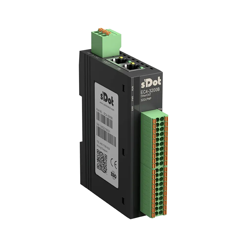
EC4-3200B · 32 DI PNP
Terminals A1–A20 = upper block, B1–B20 = lower block.
| ESI type | Product code | Inputs | Outputs |
|---|---|---|---|
| EC4-3200B | 0x0000000D | 32 × BOOL | — |
Digital inputs X00–X1F
| Terminal | Signal | Object | Name in the ESI |
|---|---|---|---|
| A1 | X00 | 0x6000:01 | Channel In1 |
| A2 | X01 | 0x6000:02 | Channel In2 |
| A3 | X02 | 0x6000:03 | Channel In3 |
| A4 | X03 | 0x6000:04 | Channel In4 |
| A5 | X04 | 0x6000:05 | Channel In5 |
| A6 | X05 | 0x6000:06 | Channel In6 |
| A7 | X06 | 0x6000:07 | Channel In7 |
| A8 | X07 | 0x6000:08 | Channel In8 |
| A11 | X08 | 0x6000:09 | Channel In9 |
| A12 | X09 | 0x6000:0A | Channel In10 |
| A13 | X0A | 0x6000:0B | Channel In11 |
| A14 | X0B | 0x6000:0C | Channel In12 |
| A15 | X0C | 0x6000:0D | Channel In13 |
| A16 | X0D | 0x6000:0E | Channel In14 |
| A17 | X0E | 0x6000:0F | Channel In15 |
| A18 | X0F | 0x6000:10 | Channel In16 |
| B1 | X10 | 0x6000:11 | Channel In17 |
| B2 | X11 | 0x6000:12 | Channel In18 |
| B3 | X12 | 0x6000:13 | Channel In19 |
| B4 | X13 | 0x6000:14 | Channel In20 |
| B5 | X14 | 0x6000:15 | Channel In21 |
| B6 | X15 | 0x6000:16 | Channel In22 |
| B7 | X16 | 0x6000:17 | Channel In23 |
| B8 | X17 | 0x6000:18 | Channel In24 |
| B11 | X18 | 0x6000:19 | Channel In25 |
| B12 | X19 | 0x6000:1A | Channel In26 |
| B13 | X1A | 0x6000:1B | Channel In27 |
| B14 | X1B | 0x6000:1C | Channel In28 |
| B15 | X1C | 0x6000:1D | Channel In29 |
| B16 | X1D | 0x6000:1E | Channel In30 |
| B17 | X1E | 0x6000:1F | Channel In31 |
| B18 | X1F | 0x6000:20 | Channel In32 |
Show wiring “PNP sensors on DI”
No startup parameters: the input filter is fixed at 3 ms.
EC4-0032B · 32 DO PNP 0.5 A
Terminals A1–A20 = upper block, B1–B20 = lower block.
| ESI type | Product code | Inputs | Outputs |
|---|---|---|---|
| EC4-0032B(W) | 0x0000000B | — | 32 × BOOL |
Digital outputs Y00–Y1F
| Terminal | Signal | Object | Name in the ESI |
|---|---|---|---|
| A1 | Y00 | 0x7000:01 | Channel Out1 |
| A2 | Y01 | 0x7000:02 | Channel Out2 |
| A3 | Y02 | 0x7000:03 | Channel Out3 |
| A4 | Y03 | 0x7000:04 | Channel Out4 |
| A5 | Y04 | 0x7000:05 | Channel Out5 |
| A6 | Y05 | 0x7000:06 | Channel Out6 |
| A7 | Y06 | 0x7000:07 | Channel Out7 |
| A8 | Y07 | 0x7000:08 | Channel Out8 |
| A11 | Y08 | 0x7000:09 | Channel Out9 |
| A12 | Y09 | 0x7000:0A | Channel Out10 |
| A13 | Y0A | 0x7000:0B | Channel Out11 |
| A14 | Y0B | 0x7000:0C | Channel Out12 |
| A15 | Y0C | 0x7000:0D | Channel Out13 |
| A16 | Y0D | 0x7000:0E | Channel Out14 |
| A17 | Y0E | 0x7000:0F | Channel Out15 |
| A18 | Y0F | 0x7000:10 | Channel Out16 |
| B1 | Y10 | 0x7000:11 | Channel Out17 |
| B2 | Y11 | 0x7000:12 | Channel Out18 |
| B3 | Y12 | 0x7000:13 | Channel Out19 |
| B4 | Y13 | 0x7000:14 | Channel Out20 |
| B5 | Y14 | 0x7000:15 | Channel Out21 |
| B6 | Y15 | 0x7000:16 | Channel Out22 |
| B7 | Y16 | 0x7000:17 | Channel Out23 |
| B8 | Y17 | 0x7000:18 | Channel Out24 |
| B11 | Y18 | 0x7000:19 | Channel Out25 |
| B12 | Y19 | 0x7000:1A | Channel Out26 |
| B13 | Y1A | 0x7000:1B | Channel Out27 |
| B14 | Y1B | 0x7000:1C | Channel Out28 |
| B15 | Y1C | 0x7000:1D | Channel Out29 |
| B16 | Y1D | 0x7000:1E | Channel Out30 |
| B17 | Y1E | 0x7000:1F | Channel Out31 |
| B18 | Y1F | 0x7000:20 | Channel Out32 |
Show wiring “Valve and lamp on DO”
Startup parameters (object 0x8000)
| Object | Name in the ESI | Default | Meaning |
|---|---|---|---|
| 0x8000:01 | BusFault_Clear/Hold | 0 | Outputs on bus failure: 0 = switch off (factory default), 1 = hold state (value derived) |
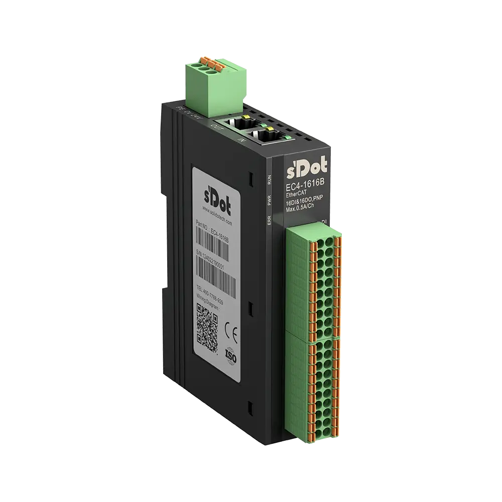
EC4-1616B · 16 DI / 16 DO PNP 0.5 A
Terminals A1–A20 = upper block, B1–B20 = lower block.
| ESI type | Product code | Inputs | Outputs |
|---|---|---|---|
| EC4-1616B(W) | 0x00000006 | 16 × BOOL | 16 × BOOL |
Digital inputs X00–X0F
| Terminal | Signal | Object | Name in the ESI |
|---|---|---|---|
| A1 | X00 | 0x6000:01 | Channel In1 |
| A2 | X01 | 0x6000:02 | Channel In2 |
| A3 | X02 | 0x6000:03 | Channel In3 |
| A4 | X03 | 0x6000:04 | Channel In4 |
| A5 | X04 | 0x6000:05 | Channel In5 |
| A6 | X05 | 0x6000:06 | Channel In6 |
| A7 | X06 | 0x6000:07 | Channel In7 |
| A8 | X07 | 0x6000:08 | Channel In8 |
| A11 | X08 | 0x6000:09 | Channel In9 |
| A12 | X09 | 0x6000:0A | Channel In10 |
| A13 | X0A | 0x6000:0B | Channel In11 |
| A14 | X0B | 0x6000:0C | Channel In12 |
| A15 | X0C | 0x6000:0D | Channel In13 |
| A16 | X0D | 0x6000:0E | Channel In14 |
| A17 | X0E | 0x6000:0F | Channel In15 |
| A18 | X0F | 0x6000:10 | Channel In16 |
Show wiring “PNP sensors on DI”
Digital outputs Y00–Y0F
| Terminal | Signal | Object | Name in the ESI |
|---|---|---|---|
| B1 | Y00 | 0x7000:01 | Channel Out1 |
| B2 | Y01 | 0x7000:02 | Channel Out2 |
| B3 | Y02 | 0x7000:03 | Channel Out3 |
| B4 | Y03 | 0x7000:04 | Channel Out4 |
| B5 | Y04 | 0x7000:05 | Channel Out5 |
| B6 | Y05 | 0x7000:06 | Channel Out6 |
| B7 | Y06 | 0x7000:07 | Channel Out7 |
| B8 | Y07 | 0x7000:08 | Channel Out8 |
| B11 | Y08 | 0x7000:09 | Channel Out9 |
| B12 | Y09 | 0x7000:0A | Channel Out10 |
| B13 | Y0A | 0x7000:0B | Channel Out11 |
| B14 | Y0B | 0x7000:0C | Channel Out12 |
| B15 | Y0C | 0x7000:0D | Channel Out13 |
| B16 | Y0D | 0x7000:0E | Channel Out14 |
| B17 | Y0E | 0x7000:0F | Channel Out15 |
| B18 | Y0F | 0x7000:10 | Channel Out16 |
Show wiring “Valve and lamp on DO”
Startup parameters (object 0x8000)
| Object | Name in the ESI | Default | Meaning |
|---|---|---|---|
| 0x8000:01 | BusFault_Clear/Hold | 0 | Outputs on bus failure: 0 = switch off (factory default), 1 = hold state (value derived) |
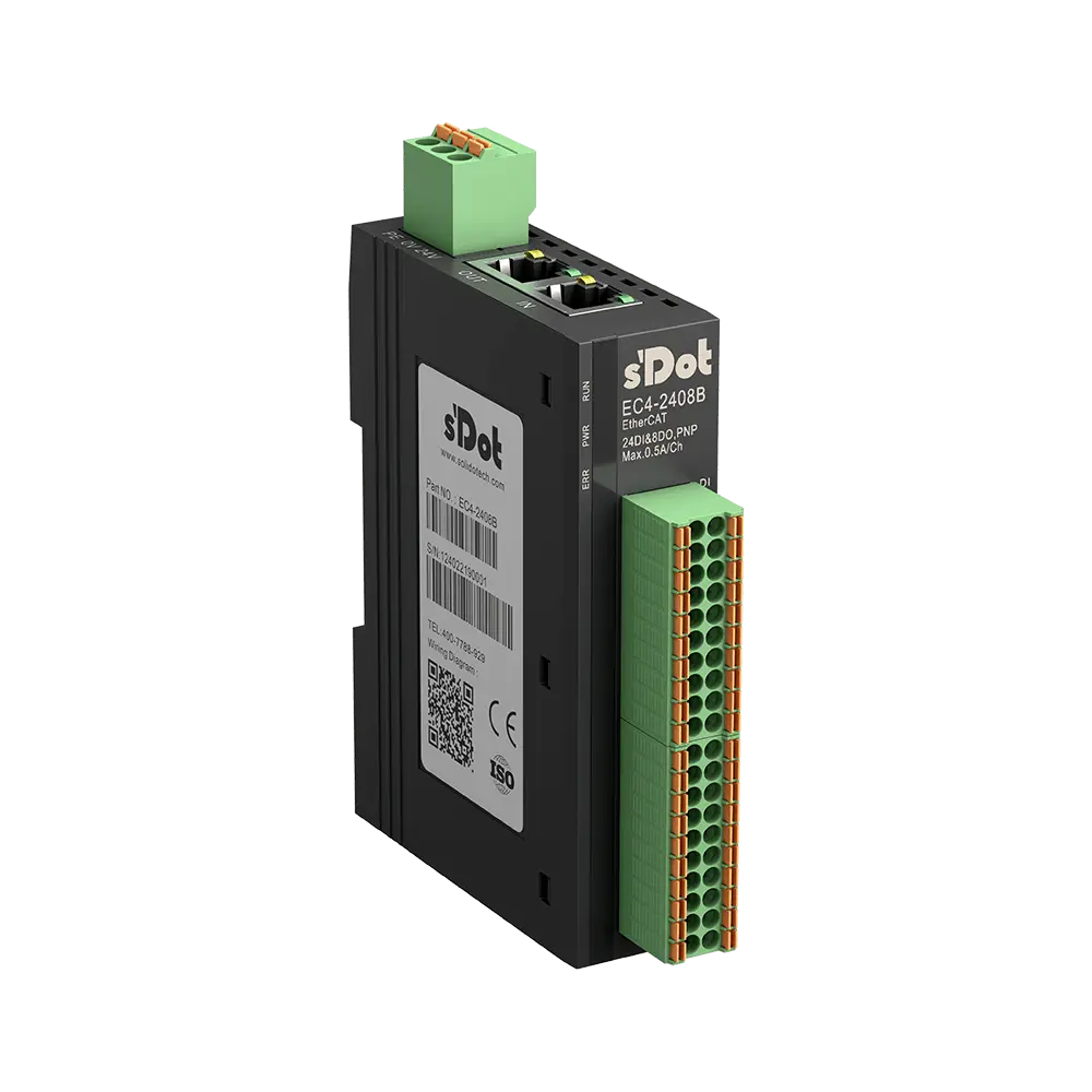
EC4-2408B · 24 DI / 8 DO PNP 0.5 A
Terminals A1–A20 = upper block, B1–B20 = lower block.
| ESI type | Product code | Inputs | Outputs |
|---|---|---|---|
| EC4-2408B(W) | 0x0042408B | 24 × BOOL | 8 × BOOL |
Digital inputs X00–X17
| Terminal | Signal | Object | Name in the ESI |
|---|---|---|---|
| A1 | X00 | 0x6000:01 | Channel In1 |
| A2 | X01 | 0x6000:02 | Channel In2 |
| A3 | X02 | 0x6000:03 | Channel In3 |
| A4 | X03 | 0x6000:04 | Channel In4 |
| A5 | X04 | 0x6000:05 | Channel In5 |
| A6 | X05 | 0x6000:06 | Channel In6 |
| A7 | X06 | 0x6000:07 | Channel In7 |
| A8 | X07 | 0x6000:08 | Channel In8 |
| A11 | X08 | 0x6000:09 | Channel In9 |
| A12 | X09 | 0x6000:0A | Channel In10 |
| A13 | X0A | 0x6000:0B | Channel In11 |
| A14 | X0B | 0x6000:0C | Channel In12 |
| A15 | X0C | 0x6000:0D | Channel In13 |
| A16 | X0D | 0x6000:0E | Channel In14 |
| A17 | X0E | 0x6000:0F | Channel In15 |
| A18 | X0F | 0x6000:10 | Channel In16 |
| B1 | X10 | 0x6000:11 | Channel In17 |
| B2 | X11 | 0x6000:12 | Channel In18 |
| B3 | X12 | 0x6000:13 | Channel In19 |
| B4 | X13 | 0x6000:14 | Channel In20 |
| B5 | X14 | 0x6000:15 | Channel In21 |
| B6 | X15 | 0x6000:16 | Channel In22 |
| B7 | X16 | 0x6000:17 | Channel In23 |
| B8 | X17 | 0x6000:18 | Channel In24 |
Show wiring “PNP sensors on DI”
Digital outputs Y00–Y07
| Terminal | Signal | Object | Name in the ESI |
|---|---|---|---|
| B11 | Y00 | 0x7000:01 | Channel Out1 |
| B12 | Y01 | 0x7000:02 | Channel Out2 |
| B13 | Y02 | 0x7000:03 | Channel Out3 |
| B14 | Y03 | 0x7000:04 | Channel Out4 |
| B15 | Y04 | 0x7000:05 | Channel Out5 |
| B16 | Y05 | 0x7000:06 | Channel Out6 |
| B17 | Y06 | 0x7000:07 | Channel Out7 |
| B18 | Y07 | 0x7000:08 | Channel Out8 |
Show wiring “Valve and lamp on DO”
Startup parameters (object 0x8000)
| Object | Name in the ESI | Default | Meaning |
|---|---|---|---|
| 0x8000:01 | BusFault_Clear/Hold | 0 | Outputs on bus failure: 0 = switch off (factory default), 1 = hold state (value derived) |
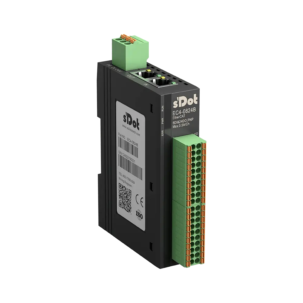
EC4-0824B · 8 DI / 24 DO PNP 0.5 A
Terminals A1–A20 = upper block, B1–B20 = lower block.
| ESI type | Product code | Inputs | Outputs |
|---|---|---|---|
| EC4-0824B(W) | 0x0040824B | 8 × BOOL | 24 × BOOL |
Digital inputs X00–X07
| Terminal | Signal | Object | Name in the ESI |
|---|---|---|---|
| A1 | X00 | 0x6000:01 | Channel In1 |
| A2 | X01 | 0x6000:02 | Channel In2 |
| A3 | X02 | 0x6000:03 | Channel In3 |
| A4 | X03 | 0x6000:04 | Channel In4 |
| A5 | X04 | 0x6000:05 | Channel In5 |
| A6 | X05 | 0x6000:06 | Channel In6 |
| A7 | X06 | 0x6000:07 | Channel In7 |
| A8 | X07 | 0x6000:08 | Channel In8 |
Show wiring “PNP sensors on DI”
Digital outputs Y00–Y1F
| Terminal | Signal | Object | Name in the ESI |
|---|---|---|---|
| A11 | Y00 | 0x7000:01 | Channel Out1 |
| A12 | Y01 | 0x7000:02 | Channel Out2 |
| A13 | Y02 | 0x7000:03 | Channel Out3 |
| A14 | Y03 | 0x7000:04 | Channel Out4 |
| A15 | Y04 | 0x7000:05 | Channel Out5 |
| A16 | Y05 | 0x7000:06 | Channel Out6 |
| A17 | Y06 | 0x7000:07 | Channel Out7 |
| A18 | Y07 | 0x7000:08 | Channel Out8 |
| B1 | Y10 | 0x7000:11 | Channel Out17 |
| B2 | Y11 | 0x7000:12 | Channel Out18 |
| B3 | Y12 | 0x7000:13 | Channel Out19 |
| B4 | Y13 | 0x7000:14 | Channel Out20 |
| B5 | Y14 | 0x7000:15 | Channel Out21 |
| B6 | Y15 | 0x7000:16 | Channel Out22 |
| B7 | Y16 | 0x7000:17 | Channel Out23 |
| B8 | Y17 | 0x7000:18 | Channel Out24 |
| B11 | Y18 | 0x7000:19 | Channel Out25 |
| B12 | Y19 | 0x7000:1A | Channel Out26 |
| B13 | Y1A | 0x7000:1B | Channel Out27 |
| B14 | Y1B | 0x7000:1C | Channel Out28 |
| B15 | Y1C | 0x7000:1D | Channel Out29 |
| B16 | Y1D | 0x7000:1E | Channel Out30 |
| B17 | Y1E | 0x7000:1F | Channel Out31 |
| B18 | Y1F | 0x7000:20 | Channel Out32 |
Show wiring “Valve and lamp on DO”
Startup parameters (object 0x8000)
| Object | Name in the ESI | Default | Meaning |
|---|---|---|---|
| 0x8000:01 | BusFault_Clear/Hold | 0 | Outputs on bus failure: 0 = switch off (factory default), 1 = hold state (value derived) |
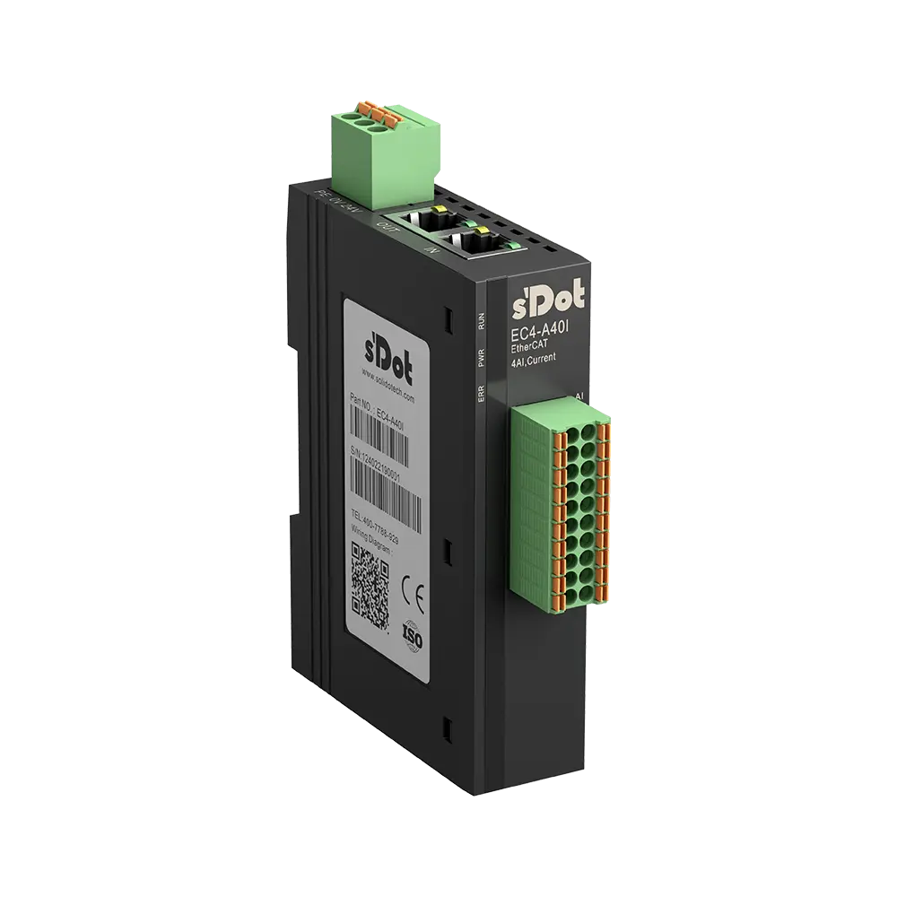
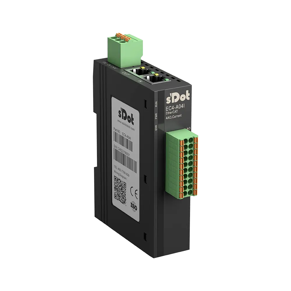
EC4-A40I · 4 AI 0/4–20 mA
| ESI type | Product code | Inputs | Outputs |
|---|---|---|---|
| EC4-A40I | 0x004A4020 | 4 × UINT | — |
Analog inputs AI0–AI3
| Terminal | Signal | Object | Name in the ESI |
|---|---|---|---|
| 1 / 11 | AI0 / COM | 0x6000:01 | Analog Input[0] (UINT) |
| 2 / 12 | AI1 / COM | 0x6000:02 | Analog Input[1] (UINT) |
| 3 / 13 | AI2 / COM | 0x6000:03 | Analog Input[2] (UINT) |
| 4 / 14 | AI3 / COM | 0x6000:04 | Analog Input[3] (UINT) |
Show wiring “2-wire transmitter 4–20 mA”Show wiring “3-wire transmitter”Show wiring “Transmitter 4-wire”
Startup parameters (object 0x8000)
| Object | Name in the ESI | Default | Meaning |
|---|---|---|---|
| 0x8000:01–04 | Channel0–3 Filter | 10 | moving average over 1–1024 A/D conversions per channel |
| 0x8000:05–08 | Channel0–3 Range Setting | 0 | 0 = 4–20 mA, 1 = 0–20 mA per channel |
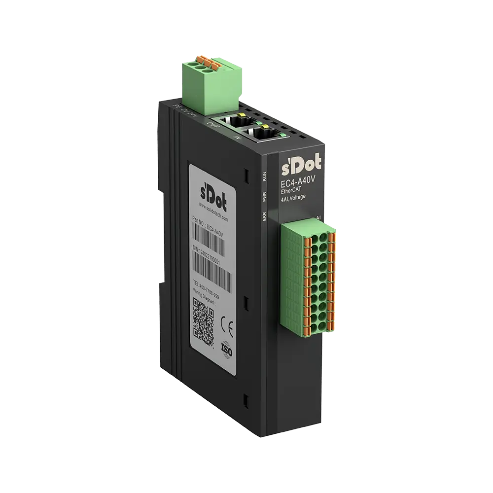
EC4-A40V · 4 AI ±10 V / 0–10 V
| ESI type | Product code | Inputs | Outputs |
|---|---|---|---|
| EC4-A40V | 0x004A4000 | 4 × INT | — |
Analog inputs AI0–AI3
| Terminal | Signal | Object | Name in the ESI |
|---|---|---|---|
| 1 / 11 | AI0 / COM | 0x6000:01 | Analog Input[0] (INT) |
| 2 / 12 | AI1 / COM | 0x6000:02 | Analog Input[1] (INT) |
| 3 / 13 | AI2 / COM | 0x6000:03 | Analog Input[2] (INT) |
| 4 / 14 | AI3 / COM | 0x6000:04 | Analog Input[3] (INT) |
Show wiring “3-wire transmitter”Show wiring “Transmitter 4-wire”
Startup parameters (object 0x8000)
| Object | Name in the ESI | Default | Meaning |
|---|---|---|---|
| 0x8000:01–04 | Channel0–3 Filter | 10 | moving average over 1–1024 A/D conversions per channel |
| 0x8000:05–08 | Channel0–3 Range Setting | 0 | 0 = ±10 V, 1 = 0–10 V per channel |
EC4-A04I · 4 AO 0/4–20 mA
| ESI type | Product code | Inputs | Outputs |
|---|---|---|---|
| EC4-A04I | 0x004A0420 | — | 4 × UINT |
Analog outputs AO0–AO3
| Terminal | Signal | Object | Name in the ESI |
|---|---|---|---|
| 1 / 11 | AO0 / COM | 0x7000:01 | Analog Output[0] (UINT) |
| 2 / 12 | AO1 / COM | 0x7000:02 | Analog Output[1] (UINT) |
| 3 / 13 | AO2 / COM | 0x7000:03 | Analog Output[2] (UINT) |
| 4 / 14 | AO3 / COM | 0x7000:04 | Analog Output[3] (UINT) |
Show wiring “Setpoint to frequency inverter”
Startup parameters (object 0x8000)
| Object | Name in the ESI | Default | Meaning |
|---|---|---|---|
| 0x8000:01 | BusFault_Clear/Hold | 0 | Outputs on bus failure: 0 = switch off (factory default), 1 = hold state (value derived) |
| 0x8000:02–05 | Channel0–3 Range Setting | 0 | 0 = 4–20 mA, 1 = 0–20 mA per channel |
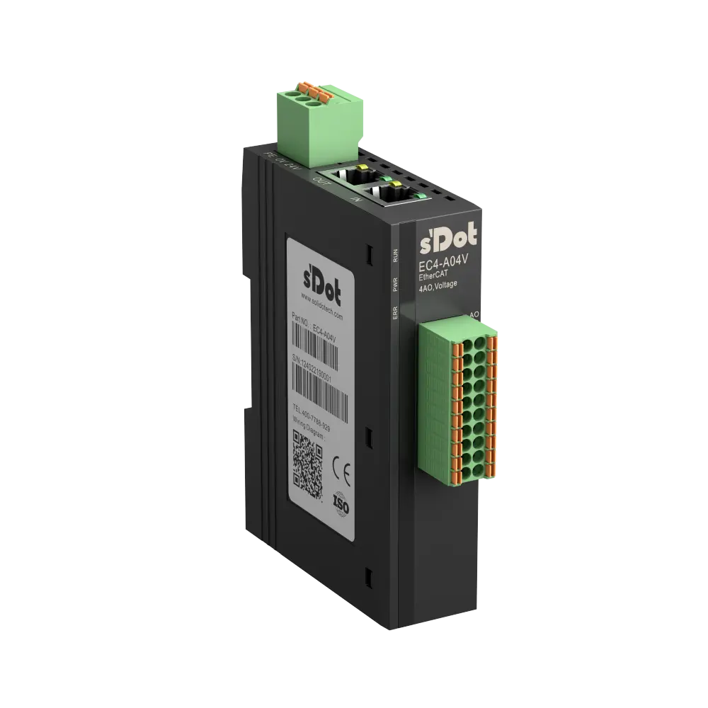
EC4-A04V · 4 AO ±10 V / 0–10 V
| ESI type | Product code | Inputs | Outputs |
|---|---|---|---|
| EC4-A04V | 0x004A0400 | — | 4 × INT |
Analog outputs AO0–AO3
| Terminal | Signal | Object | Name in the ESI |
|---|---|---|---|
| 1 / 11 | AO0 / COM | 0x7000:01 | Analog Output[0] (INT) |
| 2 / 12 | AO1 / COM | 0x7000:02 | Analog Output[1] (INT) |
| 3 / 13 | AO2 / COM | 0x7000:03 | Analog Output[2] (INT) |
| 4 / 14 | AO3 / COM | 0x7000:04 | Analog Output[3] (INT) |
Show wiring “Setpoint to frequency inverter”
Startup parameters (object 0x8000)
| Object | Name in the ESI | Default | Meaning |
|---|---|---|---|
| 0x8000:01 | BusFault_Clear/Hold | 0 | Outputs on bus failure: 0 = switch off (factory default), 1 = hold state (value derived) |
| 0x8000:02–05 | Channel0–3 Range Setting | 0 | 0 = ±10 V, 1 = 0–10 V per channel |
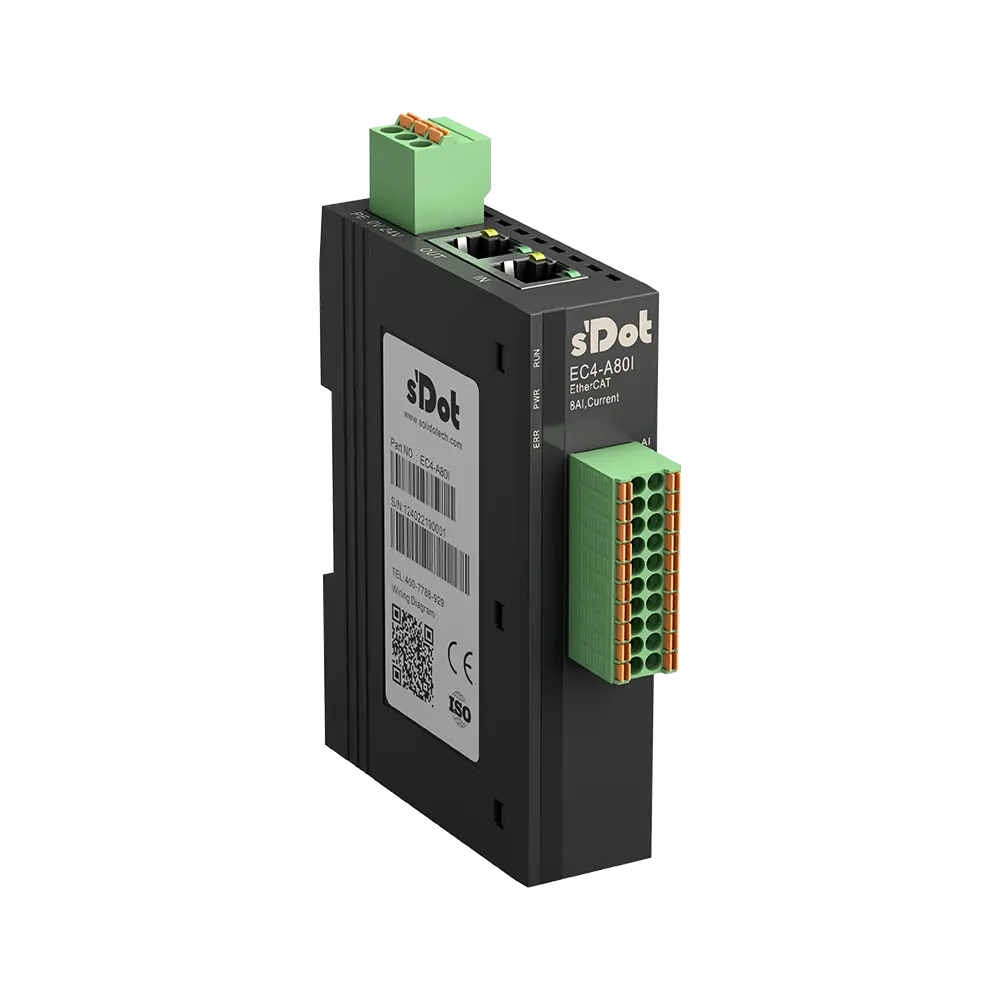
EC4-A80I · 8 AI 0/4–20 mA
| ESI type | Product code | Inputs | Outputs |
|---|---|---|---|
| EC4-A80I | 0x004A8020 | 8 × UINT | — |
Analog inputs AI0–AI7
| Terminal | Signal | Object | Name in the ESI |
|---|---|---|---|
| 1 / 11 | AI0 / COM | 0x6000:01 | Analog Input[0] (UINT) |
| 2 / 12 | AI1 / COM | 0x6000:02 | Analog Input[1] (UINT) |
| 3 / 13 | AI2 / COM | 0x6000:03 | Analog Input[2] (UINT) |
| 4 / 14 | AI3 / COM | 0x6000:04 | Analog Input[3] (UINT) |
| 5 / 15 | AI4 / COM | 0x6000:05 | Analog Input[4] (UINT) |
| 6 / 16 | AI5 / COM | 0x6000:06 | Analog Input[5] (UINT) |
| 7 / 17 | AI6 / COM | 0x6000:07 | Analog Input[6] (UINT) |
| 8 / 18 | AI7 / COM | 0x6000:08 | Analog Input[7] (UINT) |
Show wiring “2-wire transmitter 4–20 mA”Show wiring “3-wire transmitter”Show wiring “Transmitter 4-wire”
Startup parameters (object 0x8000)
| Object | Name in the ESI | Default | Meaning |
|---|---|---|---|
| 0x8000:01–08 | Channel0–7 Filter | 10 | moving average over 1–1024 A/D conversions per channel |
| 0x8000:09–10 | Channel0–7 Range Setting | 0 | 0 = 4–20 mA, 1 = 0–20 mA per channel |
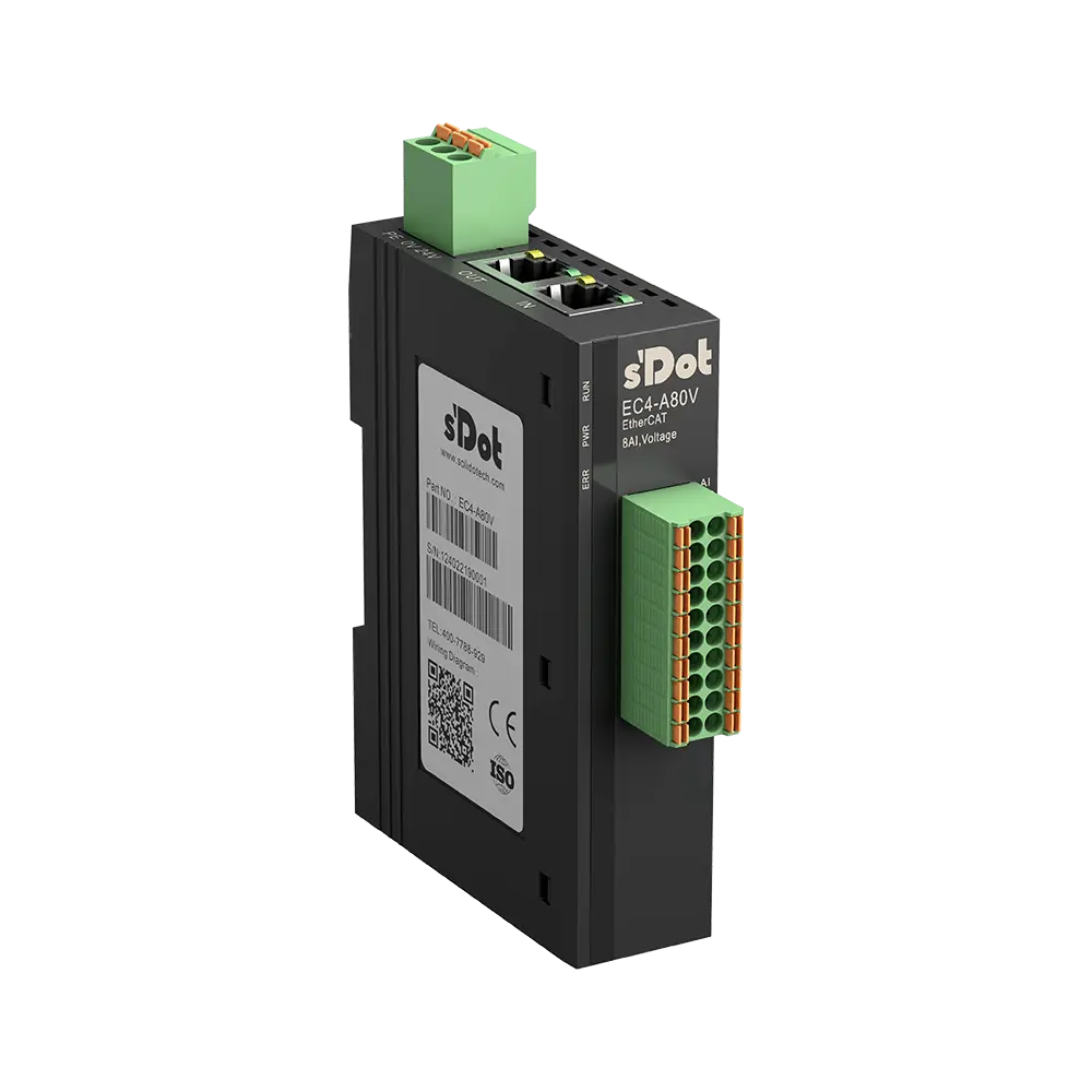
EC4-A80V · 8 AI ±10 V / 0–10 V
| ESI type | Product code | Inputs | Outputs |
|---|---|---|---|
| EC4-A80V | 0x004A8000 | 8 × INT | — |
Analog inputs AI0–AI7
| Terminal | Signal | Object | Name in the ESI |
|---|---|---|---|
| 1 / 11 | AI0 / COM | 0x6000:01 | Analog Input[0] (INT) |
| 2 / 12 | AI1 / COM | 0x6000:02 | Analog Input[1] (INT) |
| 3 / 13 | AI2 / COM | 0x6000:03 | Analog Input[2] (INT) |
| 4 / 14 | AI3 / COM | 0x6000:04 | Analog Input[3] (INT) |
| 5 / 15 | AI4 / COM | 0x6000:05 | Analog Input[4] (INT) |
| 6 / 16 | AI5 / COM | 0x6000:06 | Analog Input[5] (INT) |
| 7 / 17 | AI6 / COM | 0x6000:07 | Analog Input[6] (INT) |
| 8 / 18 | AI7 / COM | 0x6000:08 | Analog Input[7] (INT) |
Show wiring “3-wire transmitter”Show wiring “Transmitter 4-wire”
Startup parameters (object 0x8000)
| Object | Name in the ESI | Default | Meaning |
|---|---|---|---|
| 0x8000:01–08 | Channel0–7 Filter | 10 | moving average over 1–1024 A/D conversions per channel |
| 0x8000:09–10 | Channel0–7 Range Setting | 0 | 0 = ±10 V, 1 = 0–10 V per channel |
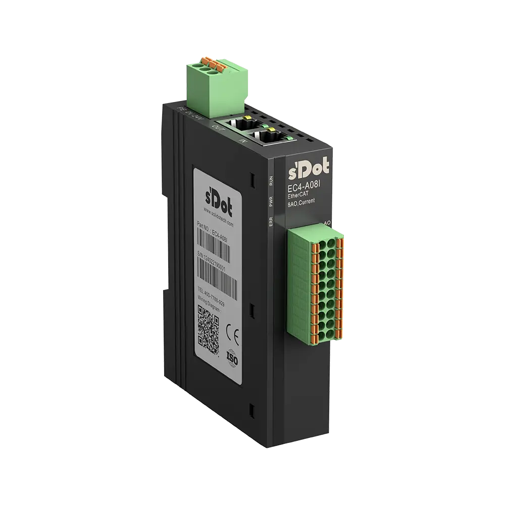
EC4-A08I · 8 AO 0/4–20 mA
| ESI type | Product code | Inputs | Outputs |
|---|---|---|---|
| EC4-A08I | 0x004A0820 | — | 8 × UINT |
Analog outputs AO0–AO7
| Terminal | Signal | Object | Name in the ESI |
|---|---|---|---|
| 1 / 11 | AO0 / COM | 0x7000:01 | Analog Output[0] (UINT) |
| 2 / 12 | AO1 / COM | 0x7000:02 | Analog Output[1] (UINT) |
| 3 / 13 | AO2 / COM | 0x7000:03 | Analog Output[2] (UINT) |
| 4 / 14 | AO3 / COM | 0x7000:04 | Analog Output[3] (UINT) |
| 5 / 15 | AO4 / COM | 0x7000:05 | Analog Output[4] (UINT) |
| 6 / 16 | AO5 / COM | 0x7000:06 | Analog Output[5] (UINT) |
| 7 / 17 | AO6 / COM | 0x7000:07 | Analog Output[6] (UINT) |
| 8 / 18 | AO7 / COM | 0x7000:08 | Analog Output[7] (UINT) |
Show wiring “Setpoint to frequency inverter”
Startup parameters (object 0x8000)
| Object | Name in the ESI | Default | Meaning |
|---|---|---|---|
| 0x8000:01 | BusFault_Clear/Hold | 0 | Outputs on bus failure: 0 = switch off (factory default), 1 = hold state (value derived) |
| 0x8000:02–09 | Channel0–7 Range Setting | 0 | 0 = 4–20 mA, 1 = 0–20 mA per channel |
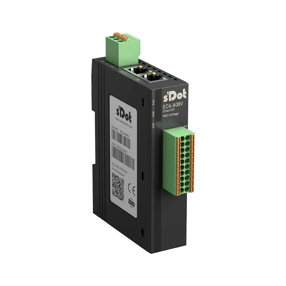
EC4-A08V · 8 AO ±10 V / 0–10 V
| ESI type | Product code | Inputs | Outputs |
|---|---|---|---|
| EC4-A08V | 0x004A0800 | — | 8 × INT |
Analog outputs AO0–AO7
| Terminal | Signal | Object | Name in the ESI |
|---|---|---|---|
| 1 / 11 | AO0 / COM | 0x7000:01 | Analog Output[0] (INT) |
| 2 / 12 | AO1 / COM | 0x7000:02 | Analog Output[1] (INT) |
| 3 / 13 | AO2 / COM | 0x7000:03 | Analog Output[2] (INT) |
| 4 / 14 | AO3 / COM | 0x7000:04 | Analog Output[3] (INT) |
| 5 / 15 | AO4 / COM | 0x7000:05 | Analog Output[4] (INT) |
| 6 / 16 | AO5 / COM | 0x7000:06 | Analog Output[5] (INT) |
| 7 / 17 | AO6 / COM | 0x7000:07 | Analog Output[6] (INT) |
| 8 / 18 | AO7 / COM | 0x7000:08 | Analog Output[7] (INT) |
Show wiring “Setpoint to frequency inverter”
Startup parameters (object 0x8000)
| Object | Name in the ESI | Default | Meaning |
|---|---|---|---|
| 0x8000:01 | BusFault_Clear/Hold | 0 | Outputs on bus failure: 0 = switch off (factory default), 1 = hold state (value derived) |
| 0x8000:02–09 | Channel0–7 Range Setting | 0 | 0 = ±10 V, 1 = 0–10 V per channel |
EC4-0012J · 12 DO relay 2 A
The ESI lists 16 output bits; the first twelve are used (Y00–Y0B), the last four are called “Reserve”.
| ESI type | Product code | Inputs | Outputs |
|---|---|---|---|
| EC4-0012J | 0x00400120 | — | 12 × BOOL + 4 reserve |
Relay outputs Y00–Y0B
| Terminal | Signal | Object | Name in the ESI |
|---|---|---|---|
| 1 | Y00 | 0x7000:01 | Channel Out1 |
| 2 | Y01 | 0x7000:02 | Channel Out2 |
| 11 | Y02 | 0x7000:03 | Channel Out3 |
| 12 | Y03 | 0x7000:04 | Channel Out4 |
| 4 | Y04 | 0x7000:05 | Channel Out5 |
| 5 | Y05 | 0x7000:06 | Channel Out6 |
| 14 | Y06 | 0x7000:07 | Channel Out7 |
| 15 | Y07 | 0x7000:08 | Channel Out8 |
| 7 | Y08 | 0x7000:09 | Channel Out9 |
| 8 | Y09 | 0x7000:0A | Channel Out10 |
| 17 | Y0A | 0x7000:0B | Channel Out11 |
| 18 | Y0B | 0x7000:0C | Channel Out12 |
| – | – | 0x7000:0D–10 | Reserve 1–4 (not used) |
Startup parameters (object 0x8000)
| Object | Name in the ESI | Default | Meaning |
|---|---|---|---|
| 0x8000:01 | BusFault_Clear/Hold | 0 | Outputs on bus failure: 0 = switch off (factory default), 1 = hold state (value derived) |
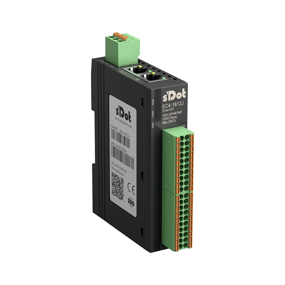
EC4-1612J · 16 DI NPN/PNP / 12 DO relay 2 A
The ESI lists 16 output bits; the first twelve are used (Y00–Y0B), the last four are called “Reserve”.
| ESI type | Product code | Inputs | Outputs |
|---|---|---|---|
| EC4-1612J | 0x00416120 | 16 × BOOL | 12 × BOOL + 4 reserve |
Digital inputs X00–X0F
| Terminal | Signal | Object | Name in the ESI |
|---|---|---|---|
| A1 | X00 | 0x6000:01 | Channel In1 |
| A2 | X01 | 0x6000:02 | Channel In2 |
| A3 | X02 | 0x6000:03 | Channel In3 |
| A4 | X03 | 0x6000:04 | Channel In4 |
| A5 | X04 | 0x6000:05 | Channel In5 |
| A6 | X05 | 0x6000:06 | Channel In6 |
| A7 | X06 | 0x6000:07 | Channel In7 |
| A8 | X07 | 0x6000:08 | Channel In8 |
| A11 | X08 | 0x6000:09 | Channel In9 |
| A12 | X09 | 0x6000:0A | Channel In10 |
| A13 | X0A | 0x6000:0B | Channel In11 |
| A14 | X0B | 0x6000:0C | Channel In12 |
| A15 | X0C | 0x6000:0D | Channel In13 |
| A16 | X0D | 0x6000:0E | Channel In14 |
| A17 | X0E | 0x6000:0F | Channel In15 |
| A18 | X0F | 0x6000:10 | Channel In16 |
Show wiring “PNP sensors on DI”
Relay outputs Y00–Y0B
| Terminal | Signal | Object | Name in the ESI |
|---|---|---|---|
| B1 | Y00 | 0x7000:01 | Channel Out1 |
| B2 | Y01 | 0x7000:02 | Channel Out2 |
| B11 | Y02 | 0x7000:03 | Channel Out3 |
| B12 | Y03 | 0x7000:04 | Channel Out4 |
| B4 | Y04 | 0x7000:05 | Channel Out5 |
| B5 | Y05 | 0x7000:06 | Channel Out6 |
| B14 | Y06 | 0x7000:07 | Channel Out7 |
| B15 | Y07 | 0x7000:08 | Channel Out8 |
| B7 | Y08 | 0x7000:09 | Channel Out9 |
| B8 | Y09 | 0x7000:0A | Channel Out10 |
| B17 | Y0A | 0x7000:0B | Channel Out11 |
| B18 | Y0B | 0x7000:0C | Channel Out12 |
| – | – | 0x7000:0D–10 | Reserve 1–4 (not used) |
Startup parameters (object 0x8000)
| Object | Name in the ESI | Default | Meaning |
|---|---|---|---|
| 0x8000:01 | BusFault_Clear/Hold | 0 | Outputs on bus failure: 0 = switch off (factory default), 1 = hold state (value derived) |
Range codes and conversion of the analog channels
Voltage (EC4-A40V, -A80V, -A04V, -A08V)
| Code | Range | Value range | Input formula (D = value) | Output formula |
|---|---|---|---|---|
| 0 | ±10 V | −32768 … 32767 | D = 65535/20 · U | U = 20 · D / 65535 |
| 1 | 0–10 V | 0 … 32767 | D = 32767/10 · U | U = 10 · D / 32767 |
Current (EC4-A40I, -A80I, -A04I, -A08I)
| Code | Range | Value range | Input formula (D = value) | Output formula |
|---|---|---|---|---|
| 0 | 4–20 mA | 0 … 65535 | D = 65535/16 · I − 16384 | I = 16 · (D + 16384) / 65535 |
| 1 | 0–20 mA | 0 … 65535 | D = 65535/20 · I | I = 20 · D / 65535 |
Example from the manual table: 5 V in the ±10 V range gives D = 16384, 12 mA in the 4–20 mA range gives D = 32767.
Range per channel via “Range Setting” in object 0x8000 as a startup parameter (manual chap. 3.3, 7.1.3).
If it does not work
| Problem | Check |
|---|---|
| Module is not found or not recognized during the scan | ESI file installed? Current version from EC4-XML V1.2? Software restarted after installation? (manual chap. 8.1) |
| Module does not go to OP | Project created and activated? Supply OK? IN/OUT cables correct? With Sysmac: node address written and module power-cycled afterwards? (chap. 8.2) |
| RUN keeps flashing | 5 Hz = Pre-OP, 2 Hz = Safe-OP: the master has not yet switched the module to OP – activate or download the configuration. |
| Analog value is wrong | Check the Range Setting of the channel (0x8000) and convert with the formula for the selected range. |
| Outputs stay on after bus failure | 0x8000:01 BusFault_Clear/Hold is set to 1 (Hold). |
For specialists
| Item | Value |
|---|---|
| Vendor ID | 0x00884443 (Nanjing Solidot Electronic Technology Co., Ltd) |
| Revision | 0x00000001 for all EC4 types in ESI V4.04 |
| Mailbox | CoE, SM0/SM1 128 bytes each |
| Process data | fixed PDOs 0x1A00 (inputs, object 0x6000) and 0x1600 (outputs, object 0x7000) |
| Distributed Clocks | not provided for the I/O modules (ESI without DC), operation in Free Run or SM-synchronous |
| Digital input filter | fixed at 3 ms, not adjustable per channel (chap. 7.1.2) |
| Analog filter | moving average, 1–1024 conversions per channel, factory default 10; sampling 800 µs for 8 channels, 400 µs for 4 channels (chap. 7.1.4) |
- That “Channel In1” or “Channel Out1” (subindex 1) corresponds to channel X00 or Y00 is derived from the order of the entries in the ESI; the manual only shows examples.
- After changing startup parameters, reload the configuration; with Sysmac Studio, power-cycle the controller and the module (manual chap. 7).
Source: EC4 Series User Manual V1.18 (11/2025), chap. 3, 4.2, 7, 8; ESI EcatTerminal-EC4_V4.04_BOOL.xml (EC4-XML V1.2, 10.04.2026).
First steps with the Solidot EC4
The EC4 brings inputs and outputs straight into EtherCAT: two sockets IN and OUT, spring-clamp terminals, integration via an ESI file. This guide applies to all EC4 models in the shop – digital with 16 or 32 channels, relay and analog with four or eight channels. It takes you from the DIN rail to the first signal in the master: supply, wire, install the ESI, scan and test.
Mount and remove only with the power off (manual chap. 5).
The module has protection class IP20 and belongs in a control cabinet or an enclosure.
Set up the system supply (module electronics) and the field supply (inputs and outputs) separately and do not mix them.
Ground PE at the supply terminal securely.
Relay modules: only DC voltage up to 48 V at the contacts (note in the connection diagram).
1Mount on the DIN railRequired
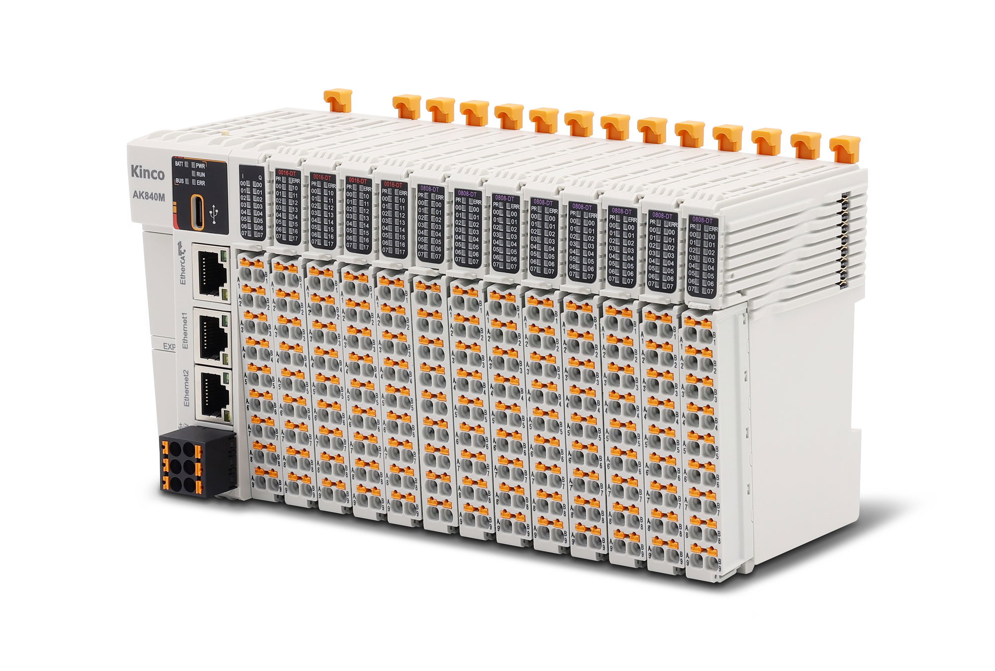
The module measures 25 × 102 × 72 mm (W × H × D), weighs about 140 g and snaps onto a 35 mm DIN rail. It must be mounted vertically so that air can flow through the housing.
Operating temperature −10 to +60 °C. Minimum clearances and connector dimensions are in the “Dimensions & mounting” tab.
Mounting
Pull the latch at the bottom of the module outwards until it audibly clicks into place.
Hook the module onto the top of the DIN rail and swing it onto the rail.
Push the latch towards the rail until it clicks.
Removal: insert a flat-blade screwdriver into the latch, lever it towards the module and swing the module off.
Source: Manual chap. 3.1, 5
2Connect system and field supplyRequired
The system supply powers the electronics: 24 V DC (18–36 V), max. 500 mA, at the three-pole terminal on the top, assigned 24V, 0V and PE.
The field supply powers the inputs and outputs via 24V/0V in the terminal block (terminal 9/10 and 19/20, each pair connected internally). Modules with two blocks need it on both blocks.
Relay modules (EC4-0012J, EC4-1612J): the relay block gets 24 V at terminal 10 and 0 V at terminal 20. You supply the loads via COM0–COM2 from a separate load supply.
The manual recommends twisted wires for the supply line. The signal terminals are rated for 9.5 A; the cross-sections in the connection diagram are derived from this and from the total current.
After switching on, PWR lights up green.
Show wiring “System supply 24 V”Show wiring “Field supply 24 V”
Source: Manual chap. 3.1, 3.2, 3.5, 6.1, 6.2, connection diagrams chap. 6.3
3Wire inputs and outputsRequired
Strip 10 mm of insulation; use a wire ferrule (10 mm) for fine-stranded wires. Press the button above the terminal with a flat-blade screwdriver up to 3 mm wide and insert the wire.
Digital inputs of the B models are PNP, filter fixed at 3 ms. On the EC4-1612J the inputs are NPN/PNP compatible: COM to 0 V for PNP sensors, to +24 V for NPN sensors.
Transistor outputs switch +24 V, max. 500 mA. Relay outputs switch up to 2 A in three groups of four contacts each (COM0: Y00–Y03, COM1: Y04–Y07, COM2: Y08–Y0B).
Analog channels: signal to AI or AO (terminal 1–8), reference to COM (terminal 11–18), twisted and shielded.
Show wiring “PNP sensors on DI”Show wiring “Valve and lamp on DO”Show wiring “Loads on relays”Show wiring “Transmitter 4-wire”Show wiring “3-wire transmitter”Show wiring “2-wire transmitter 4–20 mA”Show wiring “Setpoint to frequency inverter”
Source: Manual chap. 3.2, 3.3, 6.1–6.3, 7.1.2
4Have the ESI file readyRequired
Your EtherCAT master only knows the EC4 once it has its device description (ESI). The ZIP “EC4-XML V1.2” under Downloads contains one file for all models: EcatTerminal-EC4_V4.04_BOOL.xml.
The manual still gives older file names (“Solidot EC4_V1.0.2.xml” or “V1.1.7”). Use the file from the ZIP. You only need the two versions in the subfolder if your controller cannot map single bits.
The ESI type and product code for your model are in the EtherCAT tab.
Source: Manual chap. 7.2; ESI V4.04
5Integrate the module in the master (TwinCAT 3)Required
Plug the cable from the master into IN. You do not need an IP address or a device name: the master finds the module during the scan by its position in the line.
The manual shows the integration in detail with TwinCAT 3, CODESYS V3.5 and Omron Sysmac Studio. Here is the short version for TwinCAT; the other two are in the EtherCAT tab.
TwinCAT 3
Copy the ESI file to C:\TwinCAT\3.1\Config\Io\EtherCAT and restart TwinCAT.
Open TwinCAT XAE and create a “New TwinCAT Project”.
Right-click I/O → Devices → Scan and select the network card connected to the module.
Confirm “Scan for boxes” and “Activate Free Run” with Yes each.
Success: the “Online” tab shows the state OP, and RUN on the module lights steadily. If RUN flashes at 5 Hz, the module is in Pre-OP; at 2 Hz, in Safe-OP.
Show wiring “EtherCAT to the master”
Source: Manual chap. 4.2, 7.2.1
6Omron Sysmac Studio: write the node addressOptional
With Omron controllers (example in the manual: NX1P2), every module needs a node address that matches the configuration. It is written into the module.
Node address
ESI library: Configurations and Setup → EtherCAT → right-click Master → Display ESI Library → Install (File).
Insert the module from the Toolbox (Nanjing Solidot Electronic Technology Co., Ltd.) by double-clicking.
Go online, right-click Master → Write Slave Node Address, enter the address, Write.
Switch the module off and on again, then transfer the configuration (Transfer → To Controller) and power-cycle again.
Source: Manual chap. 7.2.3
7Test inputs and outputsRequired
Each channel is a separate BOOL: inputs in object 0x6000 (“Channel In1”, “Channel In2” …), outputs in object 0x7000 (“Channel Out1” …). Analog channels are 16-bit values (“Analog Input[0]” or “Analog Output[0]”).
Check in TwinCAT
Switch a sensor at X00: under Inputs → Channel In1 the value changes, and the channel LED lights green.
Set an output: Outputs → Channel Out1 → Online tab → Write, value 1 – Y00 switches, and the LED lights up.
Analog output: write Analog Output[0], e.g. 32767 in the ±10 V range for 10 V, and check with a meter.
That “Channel In1” corresponds to terminal X00 is derived from the order of the entries in the ESI. The assignment per terminal is in the EtherCAT tab.
Source: Manual chap. 3.3, 7.2.1 step 4, 7.2.3 step 9; ESI V4.04
8Set startup parametersOptional
The master writes settings into the module at startup (startup parameters, object 0x8000). In TwinCAT: select the module → Startup tab → New → select the object, enter the value. Then reload the configuration and the program.
BusFault_Clear/Hold (modules with outputs, 0x8000:01): factory default 0 – on bus failure the module switches the outputs off. With “Hold” they keep their state.
Analog modules: Range Setting per channel (factory default 0 = ±10 V or 4–20 mA) and, for inputs, a Filter per channel, moving average over 1 to 1024 conversions (factory default 10).
Parameter Value Meaning 0x8000:01 0 BusFault_Clear/Hold, factory default: outputs off on bus failure Range Setting 0 per channel, factory default; codes in the EtherCAT tab Filter 10 per analog input, 1–1024 conversions The subindexes differ by model, e.g. EC4-A80V: Filter 0x8000:01–08, Range 0x8000:09–10. The list for your model is in the EtherCAT tab.
Digital input filtering is fixed at 3 ms and cannot be adjusted.
Source: Manual chap. 3.3, 7.1; ESI V4.04 (object 0x8000)
9More devices in the lineOptional
Connect several EC4 and other EtherCAT devices one after the other: OUT of one module to IN of the next. Max. 100 m per segment, shielded cable of category 5 or higher.
After re-plugging or adding devices, scan again in the master; the order in the line determines the position.
If a module has no supply, you can no longer reach the devices behind it (derived; the manual does not mention a bypass).
Show wiring “Another device in the line”
Source: Manual chap. 3.1, 6.2
10TroubleshootingRequired
LEDs
LED State Meaning PWR (green) off no supply or faulty supply RUN (green) flashes 5 Hz Pre-OP RUN (green) flashes 2 Hz Safe-OP RUN (green) off initialization or no supply ERR (red) on error or special state in the system IN/OUT green off no network connection IN/OUT yellow off no data exchange Module is not found during the scan: ESI file installed correctly, current version, software restarted? (manual chap. 8.1)
Module does not start operating: check the project, node address (Sysmac), supply and EtherCAT cable; power-cycle after changing the node address (chap. 8.2).
Source: Manual chap. 4.2, 8
Revision 1.0 · 02.10.2026 · Source: EC4 Series User Manual V1.18 (24.11.2025); ESI EcatTerminal-EC4_V4.04_BOOL.xml (EC4-XML V1.2, 10.04.2026). Menu names as in the English user interface in the manual.. The manufacturer manual and applicable standards take precedence; installation and commissioning by a qualified electrician only.
Dimensions and mounting
All EC4 models are the same size and sit vertically on a 35 mm DIN rail. The drawing is projected from Solidot's 3D models (same housing as PN4 and MT4, shared 3D data “EC4_PN4_MT4”).
Connectors and wires
Supply 24V · 0V · PE (top)
- Type
- 3-pin, spring-clamp
- Pitch
- 5.08 mm*
- Size
- approx. 9 × 19 mm, 17 mm above the housing*
- Cross-section
- 0.3–1.5 mm² (22–16 AWG)
- Strip length
- 10 mm
Signals (front)
- Type
- 20-pin, two rows of 10 terminals, spring-clamp with push button; one block (16 channels, analog) or two blocks (32 channels and relay modules)
- Pitch
- 3.5 mm*
- Size
- approx. 13 × 36 mm per block, 16 mm in front of the housing*
- Cross-section
- 0.3–1.0 mm² (22–17 AWG)
- Strip length
- 10 mm
EtherCAT IN/OUT (top)
- Type
- 2 × RJ45 for EtherCAT cables or patch cables Cat. 5 or higher, double-shielded (STP) recommended, max. 100 m
* measured from Solidot's 3D model, not in the manual. We measured the supply connector at ≈ 5.1 mm and assume the standard pitch of 5.08 mm.
Wire ferrules with plastic collar, sleeve length 10 mm: E0310 (0.3 mm²), E0510 (0.5), E7510 (0.75), E1010 (1.0), E1510 (1.5 mm², supply only). Solid wires without ferrule.
Tools: flat-blade screwdriver up to 3 mm to open the spring clamp.
Cross-sections, ferrules and strip length: manual ch. 6.1 and 6.2. Rating as per ch. 6.1: signal terminal 200 V / 9.5 A, supply terminal 320 V / 20 A.
Mounting step by step
1Choose the installation site
Protection class IP20: the module belongs in a control cabinet or an enclosure. The cabinet needs good ventilation, e.g. a fan.
Mount the module vertically so that air flows through the housing. Do not mount it next to or above devices that give off a lot of heat. Operating temperature −10 to +60 °C, humidity up to 95 %, non-condensing.
At least 10 mm to neighbouring modules, 45 mm upwards and 25 mm downwards to devices or cable ducts. This leaves room at the top for the supply connector and patch cables.
2Mounting and removing
Mount and remove only with the power off.
Pull the latch at the bottom of the module outwards until it clicks into place.
Hook the module onto the top of the DIN rail and swing it onto the rail.
Push the latch towards the rail until it clicks.
Removing: insert a flat-blade screwdriver into the latch, lever it towards the module and swing the module off.
3Connecting the wires
Strip 10 mm of the wire. Stranded wires get a wire ferrule with a 10 mm sleeve length; solid wires go in directly.
Press down the push button above the terminal with a flat-blade screwdriver (up to 3 mm), insert the wire, release, give the wire a short pull.
Signal terminals take 0.3–1.0 mm², the supply terminal 0.3–1.5 mm². Run the supply cable twisted, use shielded pairs for analog signals.
Show wiring “System supply 24 V”Show wiring “PNP sensors on DI”
Revision 1.0 · 02.10.2026 · Source: EC4 Series User Manual V1.18 (11/2025), ch. 3.1, 5 and 6.1; Solidot 3D models EC4_PN4_MT4_1/_2 V1.00. The manufacturer manual and applicable standards take precedence; installation by a qualified electrician only.
Stuck?
Our support helps you free of charge. Tell us what you are planning and which model you use – via the contact form, by email or in the community forum.
Contact formEmail support@spstiger.deAsk in the community forum
More ways to contact us: Support contacts
We have compiled and checked this page carefully from the manufacturer’s documentation. Even so, an error may have slipped in. The manufacturer’s manual and the applicable standards always take precedence. Spotted something? Let us know – we’ll be glad to fix it.
Downloads
User manual, ESI files, 2D and 3D drawings and EPLAN macros:
Solidot EC4 remote I/O

Accessories