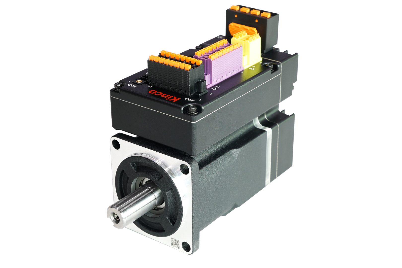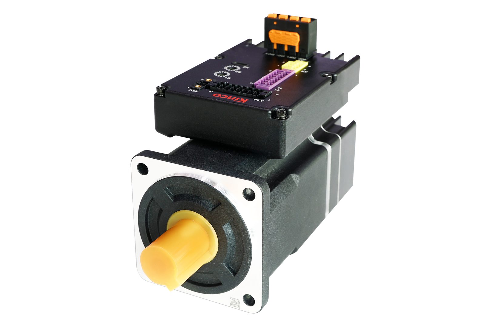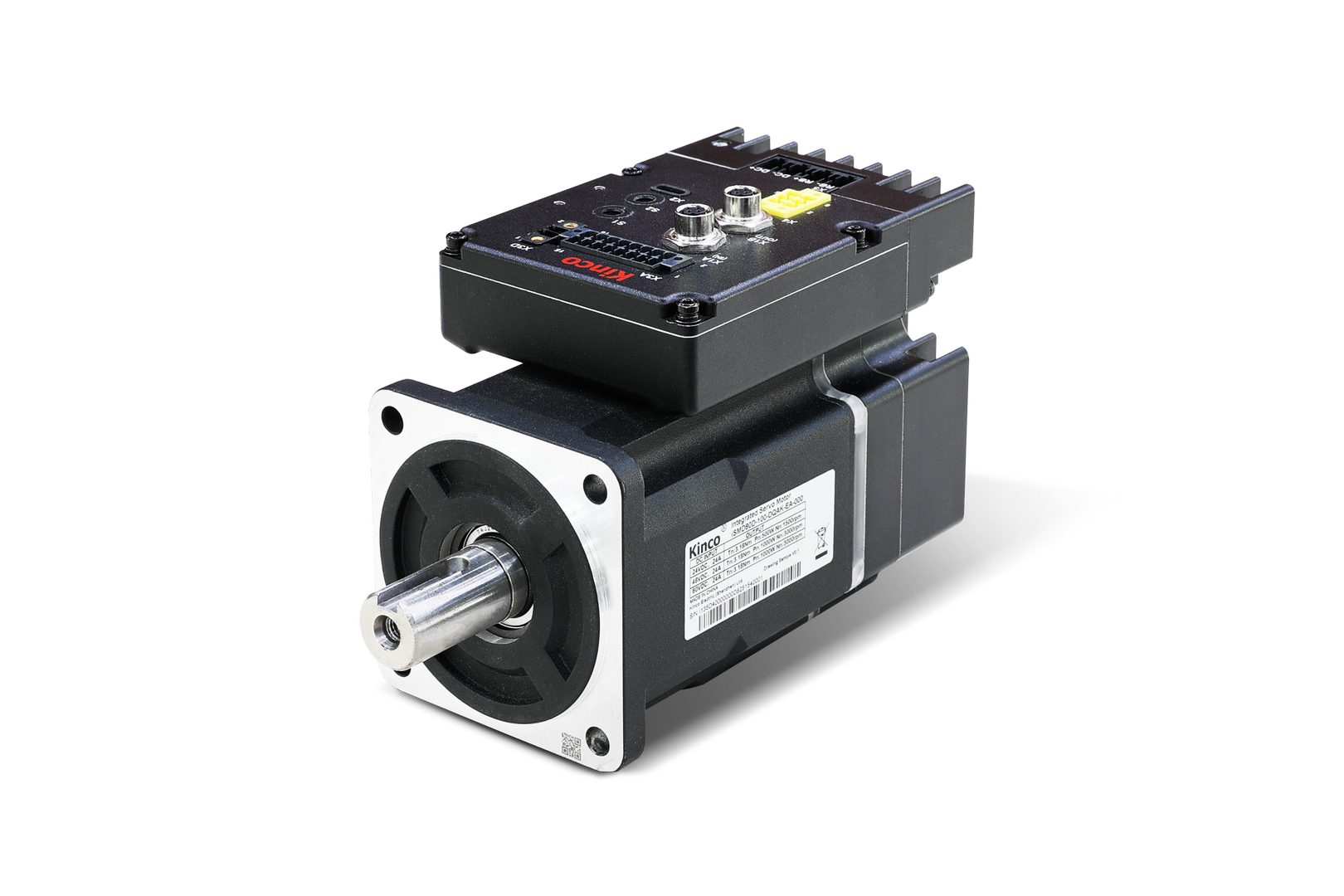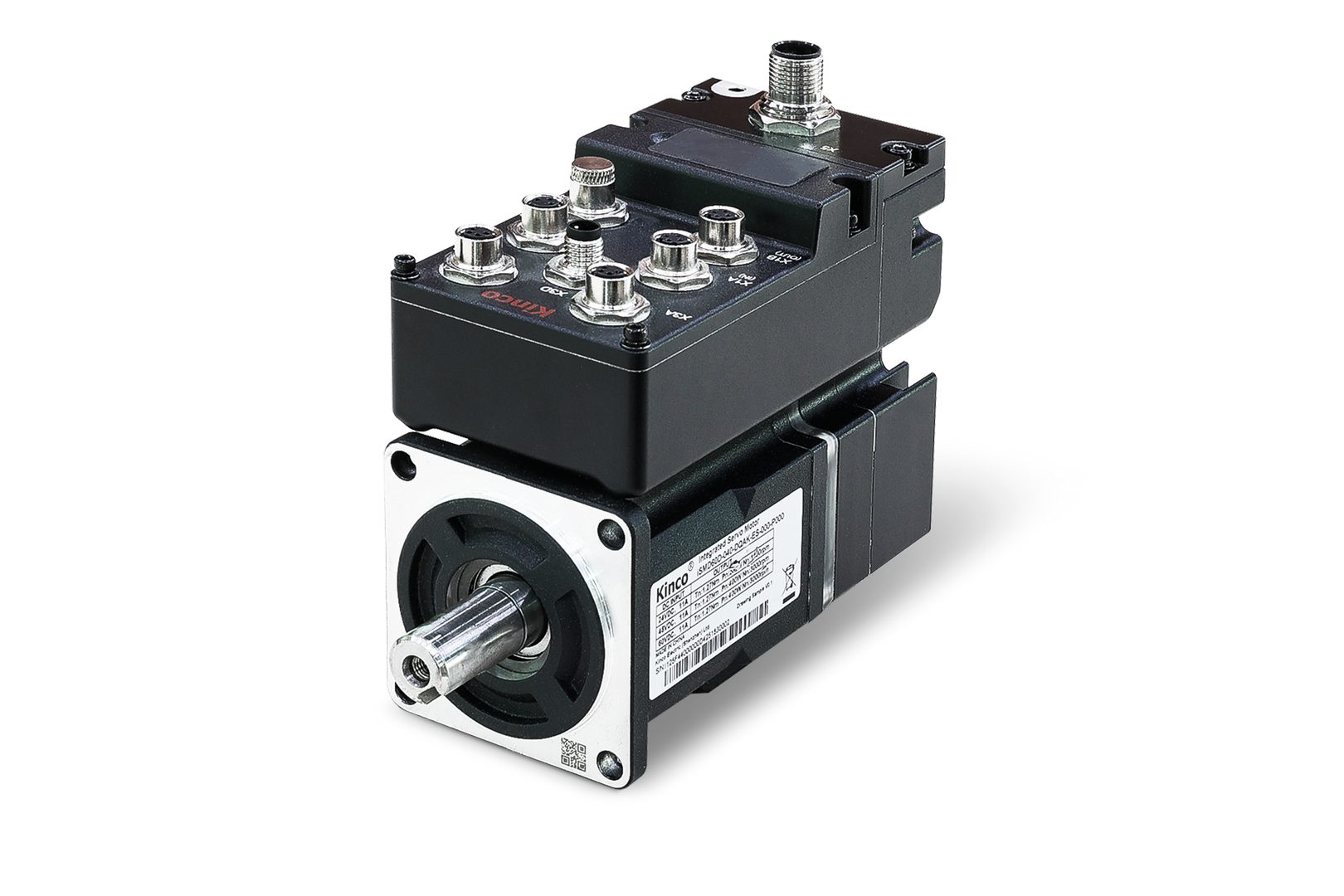



Kinco iSMD – Support, Wiring Diagram & Commissioning
Everything for your Kinco iSMD after purchase – for all 33 versions with 400, 750 and 1000 W, 24–60 V DC, with RS-485/CANopen, EtherCAT or PROFINET, with and without STO and holding brake, IP20 and IP65:
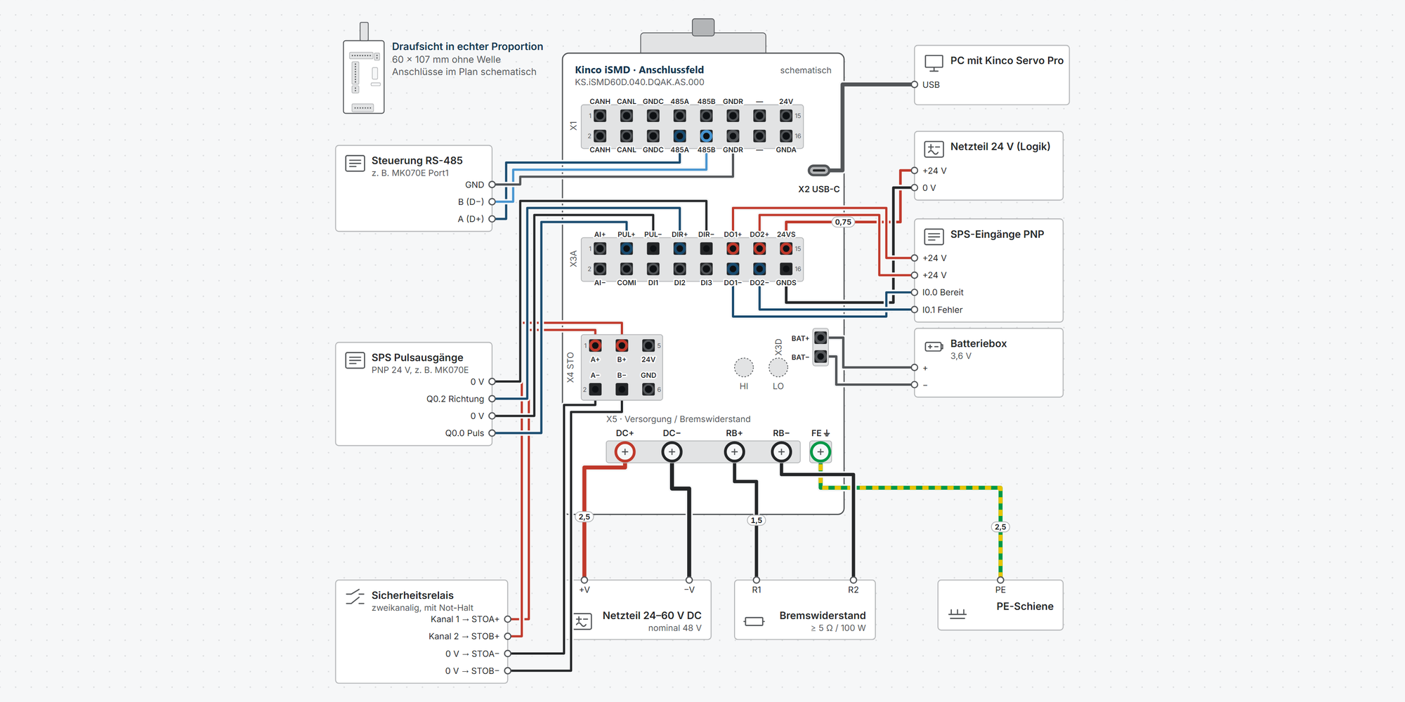
Interactive wiring diagram: power and logic supply, braking resistor, multi-turn battery, STO, digital inputs, pulse/direction, analog setpoint, digital outputs, Modbus RTU, CANopen, EtherCAT, PROFINET and USB-C, plus pin layout and mating connector of every circular connector, with cable cross-sections and parameters
First steps: commissioning in eleven steps, from wiring to the first motion with Kinco Servo Pro
Dimensions & mounting: dimensional drawing per model, drilling pattern, minimum clearances and a printable drilling template
Downloads: user manual, brochure and dimension drawings
Free support from spstiger if you get stuck
Interactive wiring diagram
Tap a terminal or wire in the drawing to see details.
Terminal overview iSMD
| Terminal | Group | mm² | Function |
|---|---|---|---|
| CANH | X1 | 0.2–1.5* | CAN high. Pins 1 and 2 are connected internally (bus in/out). |
| CANL | X1 | 0.2–1.5* | CAN low, parallel to pin 4. |
| GNDC | X1 | 0.2–1.5* | CAN signal ground. |
| 485A | X1 | 0.2–1.5* | RS-485 A, parallel to pin 8. Modbus RTU up to 115.2 kbit/s. |
| 485B | X1 | 0.2–1.5* | RS-485 B, parallel to pin 10. |
| GNDR | X1 | 0.2–1.5* | RS-485 signal ground. |
| — | X1 | 0.2–1.5* | Not assigned on the standard model (Kinco dimension drawing). Models ending in -05V0 provide 5 V for sensors here (manual chap. 1.3). |
| 24V | X1 | 0.2–1.5* | Auxiliary voltage 24 V (23–25 V), only for sensors. Load capacity 200 mA according to the specifications, 500 mA according to the pin description. |
| CANH | X1 | 0.2–1.5* | CAN high, parallel to pin 1. |
| CANL | X1 | 0.2–1.5* | CAN low, parallel to pin 3. |
| GNDC | X1 | 0.2–1.5* | CAN signal ground. |
| 485A | X1 | 0.2–1.5* | RS-485 A. |
| 485B | X1 | 0.2–1.5* | RS-485 B. |
| GNDR | X1 | 0.2–1.5* | RS-485 signal ground. |
| — | X1 | 0.2–1.5* | Not assigned on the standard model; on -05V0, reference of the 5 V auxiliary voltage. |
| GNDA | X1 | 0.2–1.5* | Reference of the 24 V auxiliary voltage. |
| X2 USB-C | X2 | – | Parameter setting and diagnostics with Kinco Servo Pro on the PC. |
| AI+ | X3A | 0.2–1.5 | Analog input ±10 V, 12 bit, differential (AA/AS models only). |
| PUL+ | X3A | 0.2–1.5 | Pulse input, 12–24 V, up to 500 kHz. Pulse/direction, CW/CCW or A/B. |
| PUL− | X3A | 0.2–1.5 | Pulse input minus. |
| DIR+ | X3A | 0.2–1.5 | Direction input, 12–24 V. Also usable as DI5 via software (20101E = 1). |
| DIR− | X3A | 0.2–1.5 | Direction input minus. |
| DO1+ | X3A | 0.2–1.5 | Open-collector output, isolated, max. 30 V, 100 mA. In the manual example: Ready. |
| DO2+ | X3A | 0.2–1.5 | Open-collector output, max. 30 V, 100 mA. In the manual example: Fault. |
| 24VS | X3A | 0.2–1.5 | Logic supply +18–30 V, max. 1 A. Optional: keeps communication and position even when the power is switched off. |
| AI− | X3A | 0.2–1.5 | Reference for the analog input. |
| COMI | X3A | 0.2–1.5 | Common terminal of the digital inputs DI1–DI3. PNP sensors: COMI to 0 V. |
| DI1 | X3A | 0.2–1.5 | Digital input, 12.5–30 V DC, up to 1 kHz. |
| DI2 | X3A | 0.2–1.5 | Digital input with probe function, response time ≤ 10 µs. |
| DI3 | X3A | 0.2–1.5 | Digital input, 12.5–30 V DC, up to 1 kHz. |
| DO1− | X3A | 0.2–1.5 | Emitter of DO1. |
| DO2− | X3A | 0.2–1.5 | Emitter of DO2. |
| GNDS | X3A | 0.2–1.5 | Reference of the logic supply. |
| A+ | X4 | 0.2–1.5 | STO channel A. Low ≤ 11 V, high ≥ 15 V at 2–2.5 mA; recommended ≤ 7 V and ≥ 18 V respectively. |
| B+ | X4 | 0.2–1.5 | STO channel B, same levels as channel A. |
| 24V | X4 | 0.2–1.5 | Output 24 V (18–30 V), max. 100 mA, only for STO, e.g. for the jumpers without safety function. |
| A− | X4 | 0.2–1.5 | STO channel A, reference. |
| B− | X4 | 0.2–1.5 | STO channel B, reference. |
| GND | X4 | 0.2–1.5 | Reference of the 24 V output. |
| BAT+ | X3D | – | Backup battery 3.6 V for the multi-turn absolute encoder (accessory BAT-iSMD). |
| BAT− | X3D | – | Backup battery minus. |
| DC+ | X5 | 0.5–6* | Power supply 24–60 V DC, nominal 48 V. |
| DC− | X5 | 0.5–6* | Power supply minus. |
| RB+ | X5 | 0.5–6* | External braking resistor. |
| RB− | X5 | 0.5–6* | External braking resistor. |
| FE ⏚ | FE | 0.5–6* | Connect the housing to the machine earth. |
* Clamping range not stated in the manual, derived.
First steps with the Kinco iSMD
From connecting to the first motion in eleven steps: supply, sort out STO, connect Kinco Servo Pro, set up the encoder, check the inputs, jog, select the operation mode and save. You only need pulse mode, fieldbus, holding brake and braking resistor if your application uses them.
Disconnect all supplies before you plug in or clamp any cables.
The power supply goes to DC+ and DC− (X5). Never connect the braking resistor to DC+ and DC−.
Use PELV power supplies; on STO models this is mandatory (manual chap. 3.3.4). Mount the motor firmly on the machine before it turns for the first time.
1Connect the supplyRequired
Power 24–60 V DC (nominal 48 V) via a circuit breaker and fuse to DC+ and DC− at X5. Connect the housing to the machine earth via the earthing screw FE (IP65: PE) by the shortest route.
The 24 V logic supply goes to 24VS and GNDS: on the IP20 model at X3A pins 15 and 16, on the IP65 model at X5 pins 2 and 1. On the models with STO (…-AS, …-ES) it is mandatory, on the others optional. With the logic supply, communication and position are retained when you switch off the power.
The wiring diagram shows cross-sections, circuit protection and connectors for your model.
The manual shows installation on an aluminum plate 255 × 255 × 8 mm for heat dissipation (chap. 2.3). The flange needs good contact with metal.
The drive switches off on overvoltage at 68 ± 2 V and on undervoltage at 16 ± 2 V.
Show wiring “Supply 48 V”Show wiring “Supply 48 V”Show wiring “Logic supply 24 V”Show wiring “Logic supply 24 V”
Source: iSMD User Manual chap. 1.3, 2.3, 3.3.1.3, 3.3.1.5, 3.3.2.5, 3.5
2STO: jumpers or safety relay (models with STO only)Required
The …-AS and …-ES models have the STO connector X4. Without a signal at both STO inputs, the drive cannot be enabled. For the first commissioning without a safety function, jumper the internal 24V to STOA+ and STOB+ and GND to STOA− and STOB−. On the IP65 model, the jumper plug M8-P6A-MWO does this.
In operation with personnel protection, STOA+ and STOB+ come from two channels of a safety relay or a safety controller. If either channel drops out, the drive switches off the torque.
Models without STO (…-AA, …-EA, …-PA) have no X4; skip this step.
Parameter Value Meaning 60F7.11 0 STO_Status: both channels high, no fault STO_Status 60F7.11
Value Fault code Meaning resettable 0 — STO A and B high, no diagnostic faults — 3 0xFF1A STO A drops out, B stays high for more than 100 ms ja 5 0xFF1B STO B drops out, A stays high for more than 100 ms ja 6 0xFF10 both channels dropped out while enabled, or low when enabling ja 1, 7 0xFF21, 0xFF20 self-diagnosis or hardware fault in the STO circuit no Ratings according to the manual: SIL 3, PL e. Allow for a response time of up to 20 ms until STO takes effect.
STO does not disconnect the voltage. A moving axis coasts to a stop. For suspended loads, STO alone is not sufficient.
Check and document STO during commissioning, then trigger it at least every three months.
Show wiring “STO jumpered (without safety function)”Show wiring “STO with safety relay”
Source: iSMD User Manual chap. 3.3.1.4, 3.3.2.4, 3.3.4, tables 3-2, 3-3, fig. 3-11, 3-12
3Connect Kinco Servo ProRequired
The iSMD is set up with the PC software Kinco Servo Pro (KS PRO). It supports the iSMD and has the clearest user interface. The older programs Kinco Servo+ and KincoServo3 (described in the manual) also work.
Connect via a USB-C data cable to X2. The USB-C socket uses the RS232 protocol, so select RS232 in Servo Pro. On the IP65 model, X2 sits under the cover next to the rotary switches.
How it works
Switch on the power or the logic supply.
In Servo Pro, open Start → Online mode.
Select the RS232 interface, choose the COM port or refresh the port list. Leave “Auto” for the baud rate and keep “Auto-Scan Node_ID” checked.
Click Start scanning. The drive appears in the list.
Select the drive and click Start config. Servo Pro creates a project in the process.
Do not power the drive via USB only: if the connection drops while saving, the drive reports an EEPROM fault.
Under Windows 7 to 11, the USB-C socket normally needs no driver.
Via X1 (RS-485), the iSMD speaks Modbus RTU at 38,400 bit/s by factory default. To use Servo Pro via RS-485, switch it to the RS232 protocol with 65100C.08 = 3, save and restart (chap. 4.1.2).
On the IP65 model, close the cover again after setting up, otherwise the protection class does not apply.
Show wiring “PC diagnostics via USB-C”
Source: iSMD User Manual chap. 4.1.2; Kinco Servo Pro help chap. 2.2
4Set up the motor and multi-turn encoderRequired
In the iSMD, motor, encoder and drive are permanently connected. The drive reads the motor data from the encoder. Under Motor Config, check that Servo Pro shows the motor correctly.
The models with Q in the name (e.g. DQAK) have a magnetic multi-turn encoder. At first power-up, the drive reports 000.4; this is normal: write 2690.00 = 10, then restart or reset the fault. To retain the position while the drive is switched off, plug the battery box into X3D.
The models with N (mechanical multi-turn encoder, 23 bit) need no battery.
Parameter Value Meaning 3041.06 2 Read motor data from the encoder (factory) 2690.00 10 Reset encoder status and revolution counter (fault 000.4) 2340.0E 1 Disable multi-turn: operate the Q encoder without battery as single-turn After 2690.00, the drive fault is not yet reset. That takes control word 0x86 or a restart.
With 2340.0E = 1, the position is lost at power-off. Homing is then required after power-up.
Battery: below 3.1 V the drive issues a warning; below 2.5 V the revolutions are lost (fault 000.4). With the drive switched on, you can replace the battery without data loss.
Show wiring “Multi-turn battery”
Source: iSMD User Manual chap. 5.7.4, 7.15, table 5-21
5Check inputs and set the rotation directionRequired
Assigned input functions can block enabling and jogging in Servo Pro. IO Config shows the assignment; Batch Clear removes all functions you do not need.
Then assign what you use, e.g. DI1 = enable. Connect limit switches as normally closed contacts: 0 means end position reached, that direction is blocked.
On the IP65 model, you also select whether the inputs switch PNP or NPN and whether the outputs work as sink or source.
Parameter Value Meaning 2010.03–06 HEX Function DI1–DI4: 0001 enable, 0002 fault reset, 0010 limit switch +, 0020 limit switch −, 0040 home switch, 1000 quick stop 2010.0F / .10 0001 / 0002 DO1 ready, DO2 fault (factory) 20101E 0 / 1 IP20: PUL and DIR as pulse input (factory) or as DI4 and DI5 20101F 0 / 1 IP65: inputs PNP (factory) or NPN, NPN only with logic supply 20101D 0 / 1 IP65: outputs as sink (factory) or source, source only with logic supply 607E.00 0 / 1 Rotation direction: 0 = counterclockwise positive (factory), 1 = clockwise positive The manual contradicts itself on the factory setting: the parameter list gives 0000 for all inputs, chap. 5.7.1 limit switches on DIN4 and DIN5. What Servo Pro shows under IO Config is what counts.
The IP20 inputs share a common terminal COMI: to 0 V for PNP sensors, to +24 V for NPN sensors.
Show wiring “Digital inputs”Show wiring “PNP sensors”Show wiring “NPN sensors”Show wiring “Digital outputs to PLC”Show wiring “Outputs to relays”
Source: iSMD User Manual chap. 3.3.1.3, 3.3.2.3, 5.7.1, 7.9; Kinco Servo Pro help chap. 2.3
6Jog mode and reversing runRequired
Under JOG you run the motor without a controller. The drive must not be enabled via an input or fieldbus, otherwise the function cannot be used.
First check that the mechanics can move freely. For the first run, choose a low speed and pay attention to rotation direction, vibration and noise.
Jog
Enter the jog speed.
Click Enable.
Hold down CW or CCW. The motor turns as long as you hold the button.
If the axis oscillates or hums, stop immediately and check the controller tuning (manual chap. 6).
Source: iSMD User Manual chap. 4.3; Kinco Servo Pro help chap. 2.3
7Select the operation mode and enableRequired
Set the operation mode in 6060.00. Enable via the control word 6040.00 according to CiA 402: first 0x06, then 0x07, then 0x0F. The status word then shows 0x0037.
Parameter Value Meaning 6040.00 0x06 → 0x07 → 0x0F Enable; 0x2F → 0x3F absolute positioning, 0x4F → 0x5F relative, 0x86 fault reset 607A.00 inc Target position in encoder increments 6098.00 35 Homing: current position becomes the zero point Operation modes 6060.00
Value Operation mode 1 Positioning 3 Speed with ramp −3 Speed direct, without ramp, e.g. for the first test run 4 Torque 6 Homing −4 Pulse mode, IP20 only 7 Interpolation via CANopen With EtherCAT, the master sets the operation mode; CSP, CSV, PP, PV, PT and HM are supported.
Source: iSMD User Manual chap. 1.3, 5.1, 5.5, table 5-2
8Pulse mode with a controller (IP20 only)Optional
In pulse mode (6060.00 = −4), the controller specifies pulse and direction. The PUL and DIR inputs accept 12–24 V up to 500 kHz. The IP65 model does not support pulse mode.
The electronic gear defines how many pulses make one motor revolution: numerator / denominator = increments per revolution / pulses per revolution. Servo Pro shows the increments per revolution under Motor Config.
Parameter Value Meaning 2508.03 0 / 1 / 2 Pulse type: CW/CCW, pulse/direction, A/B 2508.01 Numerator Electronic gear, numerator 2508.02 Denominator Electronic gear, denominator 2508.06 Filter Input filter, must be above the pulse frequency Use a shielded, twisted cable for the pulses.
Reverse the rotation direction with 607E.00 = 1.
Show wiring “Pulse / direction from PLC”
Source: iSMD User Manual chap. 5.6, table 5-16
9Fieldbus: station number and baud rateOptional
AA/AS (RS-485 and CANopen): the rotary switches HI and LO give the station number 0x00–0x7F, so HI 0–7. With HI set to C, LO sets the baud rate. Factory default: CANopen 500 kbit/s, RS-485 38,400 bit/s, Modbus RTU with 8 data bits, 1 stop bit, no parity.
EA/ES (EtherCAT): the rotary switches give the station alias 0x00–0xFF. X1A is the input from the master, X1B goes to the next node.
PA (PROFINET): no rotary switches; the controller assigns device name and address. Supported are telegrams 1, 3, 5, 9, 102, 105 and 111, IRT and DSC.
Set the rotary switches (AA/AS, EA/ES)
Switch off the drive. The switches are only read at power-up.
Set HI and LO with a 2–2.5 mm slotted screwdriver.
Switch on. After a new baud rate, the LED ring flashes green twice.
Enter the same station number or baud rate in the controller.
HI set to 8–B or D–F is invalid: the LED ring lights red and the drive reports a CAN communication fault.
At both ends of an RS-485 or CAN bus, 120 Ω between A and B or CAN_H and CAN_L.
Show wiring “Modbus RTU (RS-485)”Show wiring “CANopen”Show wiring “EtherCAT”Show wiring “PROFINET”
Source: iSMD User Manual chap. 1.3, 3.3.3, 4.1.2
10Holding brake and braking resistorOptional
The models with B in the name (e.g. DQBK) have a holding brake. The drive powers and controls it itself; no separate connection or 24 V power supply is needed for it. For the drive to control it correctly, the motor must be configured as a motor with brake.
A braking resistor at RB+ and RB− (X5, IP20 only) absorbs the energy during braking. It becomes necessary when the bus voltage rises above 63 V during braking and the drive reports overvoltage (002.0). For the IP65 model, the braking resistor module PRC-69-40-20 V2 is available.
Parameter Value Meaning 6410.17 1 Motor with brake 6410.11 70 % Duty cycle of the brake voltage (factory), recommended 40–90 % 6410.12 150 ms Brake delay (factory) 605A.00 2 Quick stop with ramp, the brake engages only afterwards (factory 0 = uncontrolled) Minimum braking resistor values: iSMD60D 5 Ω / 100 W, iSMD80D 3 Ω / 400 W. Smaller values are not permitted.
For suspended loads, choose a motor with brake.
Show wiring “Braking resistor”
Source: iSMD User Manual chap. 1.3, 5.7.2, table 5-19
11Save and back upRequired
Changed parameters are only permanent after saving. Without saving, they are gone after the next power-off.
In addition, export the parameters in Servo Pro as a .ksparam file. Use it to restore the settings or to set up further drives the same way.
Parameter Value Meaning 2FF0.01 1 Save configuration and controller parameters (10 = reset to factory default) 2FF0.03 1 Save motor parameters 2FFF.00 0xAA55 Restart the drive Common faults
Code Fault Typical cause FFF.F Motor not configured Motor data do not match, read in again under Motor Config 000.2 Encoder communication Encoder not responding 000.4 Encoder internal Multi-turn data invalid: 2690.00 = 10, check the battery (step 4) 000.8 Encoder CRC Interference, check the earthing of the drive 001.0 Overtemperature Insufficient heat dissipation via the flange, ambient above 40 °C 002.0 Overvoltage Regeneration during braking, add a braking resistor 004.0 Undervoltage Power supply too weak or voltage drops during acceleration 008.0 Overcurrent Short circuit or fault in the power stage 020.0 Following error Brake not released, mechanics stiff, limits too small 040.0 Logic voltage too low Check the logic supply 080.0 I²t motor or drive Overload or stiff mechanics On a fault, the red ERR indicator lights up. Servo Pro shows the fault code and the fault history (the last 8 faults).
Fix the fault first, then reset it (control word 0x86 or an input with the fault reset function).
Source: iSMD User Manual chap. 7.11, 7.15, 10, tables 10-1, 10-5
Revision 1.0 · 03.10.2026 · Source: Kinco iSMD User Manual (03/2026), brochure K4E45 (07/2026), Kinco Servo Pro help (05/2026). The manufacturer manual and applicable standards take precedence; installation and commissioning by a qualified electrician only.
Dimensions and mounting
Flange dimensions, drilling pattern and space requirements of the selected model. The view is simplified; the dimensions come from the Kinco dimension drawings.
All models
| Item | Rating | W × H × D (mm) | Drilling pattern (mm) | Hole ⌀ (mm) | Weight (kg) |
|---|---|---|---|---|---|
| KS.iSMD60D.040.DQAK.AA.000 | iSMD60D-040 · 400 W | 60 × 90 × 107 | pitch circle ⌀ 70, spigot ⌀ 50 | 5.5 | 1.4 |
| KS.iSMD60D.040.DQAK.AS.000 | iSMD60D-040 · 400 W | ||||
| KS.iSMD60D.040.DQBK.AA.000 | iSMD60D-040 · 400 W · holding brake | 60 × 90 × 141 | pitch circle ⌀ 70, spigot ⌀ 50 | 5.5 | 1.8 |
| KS.iSMD60D.040.DQBK.AS.000 | iSMD60D-040 · 400 W · holding brake | ||||
| KS.iSMD60D.040.DNAK.AA.000 | iSMD60D-040 · 400 W · encoder N | 60 × 90 × 114 | pitch circle ⌀ 70, spigot ⌀ 50 | 5.5 | 1.4 |
| KS.iSMD80D.075.DQAK.AA.000 | iSMD80D-075 · 750 W | 80 × 110 × 125 | pitch circle ⌀ 90, spigot ⌀ 70 | 6.5 | 2.4 |
| KS.iSMD80D.075.DQAK.AS.000 | iSMD80D-075 · 750 W | ||||
| KS.iSMD80D.075.DQBK.AA.000 | iSMD80D-075 · 750 W · holding brake | 80 × 110 × 158 | pitch circle ⌀ 90, spigot ⌀ 70 | 6.5 | 3.1 |
| KS.iSMD80D.075.DQBK.AS.000 | iSMD80D-075 · 750 W · holding brake | ||||
| KS.iSMD80D.100.DQAK.AA.000 | iSMD80D-100 · 1000 W | 80 × 110 × 140 | pitch circle ⌀ 90, spigot ⌀ 70 | 6.5 | 2.9 |
| KS.iSMD80D.100.DQAK.AS.000 | iSMD80D-100 · 1000 W | ||||
| KS.iSMD80D.100.DQBK.AA.000 | iSMD80D-100 · 1000 W · holding brake | 80 × 110 × 173 | pitch circle ⌀ 90, spigot ⌀ 70 | 6.5 | 3.6 |
| KS.iSMD80D.100.DQBK.AS.000 | iSMD80D-100 · 1000 W · holding brake | ||||
| KS.iSMD60D.040.DQAK.EA.000 | iSMD60D-040 · 400 W | 60 × 98 × 107 | pitch circle ⌀ 70, spigot ⌀ 50 | 5.5 | 1.4 |
| KS.iSMD60D.040.DQAK.PA.000 | iSMD60D-040 · 400 W | ||||
| KS.iSMD60D.040.DQBK.EA.000 | iSMD60D-040 · 400 W · holding brake | 60 × 98 × 141 | pitch circle ⌀ 70, spigot ⌀ 50 | 5.5 | 1.8 |
| KS.iSMD60D.040.DQBK.PA.000 | iSMD60D-040 · 400 W · holding brake | ||||
| KS.iSMD80D.075.DQAK.EA.000 | iSMD80D-075 · 750 W | 80 × 118 × 125 | pitch circle ⌀ 90, spigot ⌀ 70 | 6.5 | 2.4 |
| KS.iSMD80D.075.DQAK.PA.000 | iSMD80D-075 · 750 W | ||||
| KS.iSMD80D.075.DQBK.EA.000 | iSMD80D-075 · 750 W · holding brake | 80 × 118 × 158 | pitch circle ⌀ 90, spigot ⌀ 70 | 6.5 | 3.1 |
| KS.iSMD80D.075.DQBK.PA.000 | iSMD80D-075 · 750 W · holding brake | ||||
| KS.iSMD80D.100.DQAK.EA.000 | iSMD80D-100 · 1000 W | 80 × 118 × 140 | pitch circle ⌀ 90, spigot ⌀ 70 | 6.5 | 2.9 |
| KS.iSMD80D.100.DQAK.ES.000 | iSMD80D-100 · 1000 W | ||||
| KS.iSMD80D.100.DQAK.PA.000 | iSMD80D-100 · 1000 W | ||||
| KS.iSMD80D.100.DQBK.EA.000 | iSMD80D-100 · 1000 W · holding brake | 80 × 118 × 173 | pitch circle ⌀ 90, spigot ⌀ 70 | 6.5 | 3.6 |
| KS.iSMD80D.100.DQBK.ES.000 | iSMD80D-100 · 1000 W · holding brake | ||||
| KS.iSMD80D.100.DQBK.PA.000 | iSMD80D-100 · 1000 W · holding brake | ||||
| KS.iSMD60D.040.DQAK.EA.000.P000 | iSMD60D-040 · 400 W | 60 × 108 × 122 | pitch circle ⌀ 70, spigot ⌀ 50 | 5.5 | 1.6 |
| KS.iSMD60D.040.DQAK.ES.000.P000 | iSMD60D-040 · 400 W | ||||
| KS.iSMD60D.040.DQBK.EA.000.P000 | iSMD60D-040 · 400 W · holding brake | 60 × 108 × 156 | pitch circle ⌀ 70, spigot ⌀ 50 | 5.5 | 2.0 |
| KS.iSMD60D.040.DQBK.ES.000.P000 | iSMD60D-040 · 400 W · holding brake | ||||
| KS.iSMD60D.040.DNAK.EA.000.P000 | iSMD60D-040 · 400 W · encoder N | 60 × 108 × 129 | pitch circle ⌀ 70, spigot ⌀ 50 | 5.5 | 1.6 |
| KS.iSMD60D.040.DNBK.EA.000.P000 | iSMD60D-040 · 400 W · holding brake · encoder N | 60 × 108 × 163 | pitch circle ⌀ 70, spigot ⌀ 50 | 5.5 | 2.0 |
Mounting step by step
1Check the installation site
The iSMD is screwed to the machine by its flange. The IP20 version needs a dry, dust-free location; the IP65 version is protected against dust and water jets at the housing, IP54 at the shaft exit.
Ambient temperature −20 to +40 °C, humidity below 90 %, without condensation.
Altitude up to 3000 m; above 1000 m derate by 1.5 % per 100 m.
No chips, oil mist or coolant on the device, no direct sunlight, keep away from heat sources.
If oil drips onto the shaft, choose a model with a shaft seal and keep the oil level below the sealing lip.
2Fasten the flange
Four screws go through the flange into the machine plate. The spigot (3 mm deep) sits in a bore in the plate and aligns the shaft. The 1:1 drilling template shows the pitch circle, mounting holes and centering bore.
The plate dissipates the heat. The manual shows installation on an aluminum plate 255 × 255 × 8 mm (chap. 2.3).
iSMD60D: 4 × ⌀ 5.5 mm on pitch circle ⌀ 70 mm, spigot ⌀ 50 mm.
iSMD80D: 4 × ⌀ 6.5 mm on pitch circle ⌀ 90 mm, spigot ⌀ 70 mm.
Screws M5 or M6 to suit the hole diameter (derived, the manual gives no screw size). Secure every screw against loosening.
3Shaft and coupling
Motor shaft and machine shaft must be aligned. They are connected via a coupling or a clamping set. Inaccurate alignment causes vibration and can damage the bearings and encoder.
Shaft with key: iSMD60D ⌀ 14 × 30 mm, iSMD80D ⌀ 19 × 35 mm.
Pull a pulley or coupling on using the thread in the shaft end (iSMD60D M5 × 15, iSMD80D M6 × 20), never hammer it on. Use a puller to remove it.
Maximum shaft load: iSMD60D radial 245 N, axial 74 N; iSMD80D radial 392 N, axial 147 N.
Fit rotating parts with a protective cover.
4Space for connectors and cables
The connectors sit on top of the housing. Above them, keep clear the cable space given in the Kinco drawing: 50 mm for AA/AS, 60 mm for EA/ES/PA, 80 mm for the IP65 model.
For the battery box of the multi-turn encoder, the drawing allows 30 mm at the side.
Do not pull on the connectors; provide strain relief for the cables.
Bending radius at least 5 to 10 times the cable diameter; use flexible cables in drag chains.
Route power and signal cables at least 30 cm apart.
Show clearances in the drawingShow wiring “Multi-turn battery”
Revision 1.0 · 03.10.2026 · Source: Kinco dimension drawings iSMD60D/80D IP20 and IP65 (V1.0–V1.5, 2025), iSMD User Manual (03/2026) chap. 1.3, 2.1, 2.2, 2.3. The manufacturer manual and applicable standards take precedence; installation by a qualified electrician only.
Stuck?
Our support helps you free of charge. Tell us what you are planning and which model you use – via the contact form, by email or in the community forum.
Contact formEmail support@spstiger.deAsk in the community forum
More ways to contact us: Support contacts
We have compiled and checked this page carefully from the manufacturer’s documentation. Even so, an error may have slipped in. The manufacturer’s manual and the applicable standards always take precedence. Spotted something? Let us know – we’ll be glad to fix it.
Downloads
User manual, brochure and dimension drawings:
Kinco iSMD integrated servo motors