


Kinco MK series – Support, Wiring Diagram & Commissioning
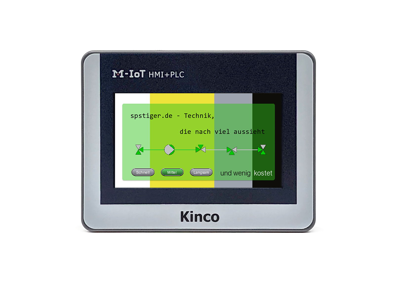
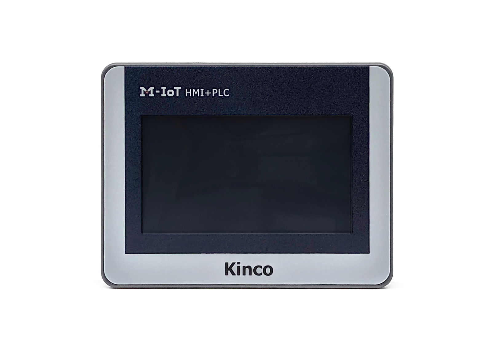
Everything for your Kinco MK-Serie after purchase – for all six MK043E and MK070E models, also with neutral front (Blank):
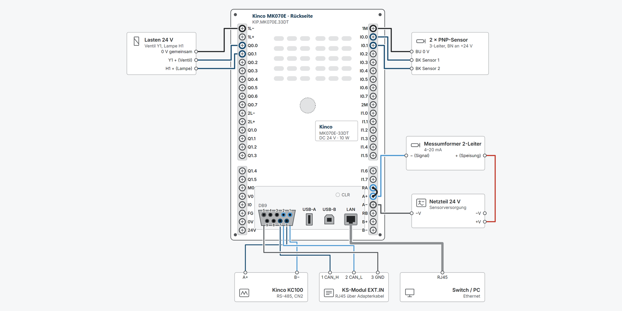
Interactive wiring diagram: power supply, inputs and outputs, relays, pulse output, high-speed counters, analog sensors, Pt100, thermocouple, Modbus RTU, KS expansion modules and Ethernet, with cable cross-sections and parameters
First steps: commissioning in ten steps, from first power-up to your first own program with an HMI screen
System menu: set IP address, clock and remote access on the HMI, to try out
Dimensions & mounting: outside dimensions, panel cut-out and a printable cut-out template
Downloads: MK series user manual
Free support from spstiger if you get stuck
Interactive wiring diagram
Tap a terminal or wire in the drawing to see details.
Terminal overview MK
| Terminal | Group | mm² | Function |
|---|---|---|---|
| 1L− | DO | 0.2–1.5* | Reference for Q0.0–Q0.7. To 0 V of the 24 V supply. |
| 1L+ | DO | 0.2–1.5* | Supplies the PNP outputs Q0.0–Q0.7. Without 1L+ the outputs do not switch. |
| Q0.0 | DO | 0.2–1.5* | PNP, 24 V DC, 200 mA. Fast pulse output (PTO/PWM). |
| Q0.1 | DO | 0.2–1.5* | PNP, 24 V DC, 200 mA. Fast pulse output (PTO/PWM). |
| Q0.2 | DO | 0.2–1.5* | PNP, 24 V DC, 200 mA. Direction output for pulse/direction. |
| Q0.3 | DO | 0.2–1.5* | PNP, 24 V DC, 200 mA. Direction output for pulse/direction. |
| Q0.4 | DO | 0.2–1.5* | PNP, 24 V DC, 200 mA. Fast pulse output (PTO/PWM). |
| Q0.5 | DO | 0.2–1.5* | PNP, 24 V DC, 200 mA. Fast pulse output (PTO/PWM). |
| Q0.6 | DO | 0.2–1.5* | PNP, 24 V DC, 200 mA. Direction output for pulse/direction. |
| Q0.7 | DO | 0.2–1.5* | PNP, 24 V DC, 200 mA. Direction output for pulse/direction. |
| 2L− | DO | 0.2–1.5* | Reference for Q1.0–Q1.5. |
| 2L+ | DO | 0.2–1.5* | Supplies the PNP outputs Q1.0–Q1.5. |
| Q1.0 | DO | 0.2–1.5* | PNP, 24 V DC, 200 mA. |
| Q1.1 | DO | 0.2–1.5* | PNP, 24 V DC, 200 mA. |
| Q1.2 | DO | 0.2–1.5* | PNP, 24 V DC, 200 mA. |
| Q1.3 | DO | 0.2–1.5* | PNP, 24 V DC, 200 mA. |
| Q1.4 | PWR | 0.2–1.5* | PNP, 24 V DC, 200 mA. |
| Q1.5 | PWR | 0.2–1.5* | PNP, 24 V DC, 200 mA. |
| M0 | PWR | 0.2–1.5* | Common reference for V0 and I0. |
| V0 | PWR | 0.2–1.5* | 0–10 V or 1–5 V, load ≥ 1 kΩ, 12 bit. Select signal type in KincoBuilder. |
| I0 | PWR | 0.2–1.5* | 0–20 mA or 4–20 mA, burden ≤ 500 Ω. |
| FG | PWR | 0.2–1.5* | Connect to the protective earth bar. |
| 0V | PWR | 0.2–1.5* | 24 V DC negative. |
| 24V | PWR | 0.2–1.5* | 24 V DC (20.4–28.8 V), power consumption max. 10 W. |
| 1M | DI | 0.2–1.5* | For I0.0–I0.7. PNP sensor (source): 1M to 0 V. NPN sensor (sink): 1M to +24 V. |
| I0.0 | DI | 0.2–1.5* | 24 V DC, PNP or NPN, 3.5 mA. Edge interrupt. HSC0: direction (mode 3) or track B (mode 9), max. 50 kHz. |
| I0.1 | DI | 0.2–1.5* | 24 V DC, PNP or NPN, 3.5 mA. Edge interrupt. HSC0: clock (mode 0, 3) or track A (mode 9), max. 50 kHz. |
| I0.2 | DI | 0.2–1.5* | 24 V DC, PNP or NPN, 3.5 mA. High-speed counter up to 50 kHz. Edge interrupt. |
| I0.3 | DI | 0.2–1.5* | 24 V DC, PNP or NPN, 3.5 mA. High-speed counter up to 50 kHz. Edge interrupt. |
| I0.4 | DI | 0.2–1.5* | 24 V DC, PNP or NPN, 3.5 mA. High-speed counter up to 50 kHz. |
| I0.5 | DI | 0.2–1.5* | 24 V DC, PNP or NPN, 3.5 mA. High-speed counter up to 50 kHz. |
| I0.6 | DI | 0.2–1.5* | 24 V DC, PNP or NPN, 3.5 mA. High-speed counter up to 50 kHz. |
| I0.7 | DI | 0.2–1.5* | 24 V DC, PNP or NPN, 3.5 mA. High-speed counter up to 50 kHz. |
| 2M | DI | 0.2–1.5* | For I1.0–I1.7, wiring as for 1M. |
| I1.0 | DI | 0.2–1.5* | 24 V DC, PNP or NPN, 3.5 mA. |
| I1.1 | DI | 0.2–1.5* | 24 V DC, PNP or NPN, 3.5 mA. |
| I1.2 | DI | 0.2–1.5* | 24 V DC, PNP or NPN, 3.5 mA. |
| I1.3 | DI | 0.2–1.5* | 24 V DC, PNP or NPN, 3.5 mA. |
| I1.4 | DI | 0.2–1.5* | 24 V DC, PNP or NPN, 3.5 mA. |
| I1.5 | DI | 0.2–1.5* | 24 V DC, PNP or NPN, 3.5 mA. |
| I1.6 | AI | 0.2–1.5* | 24 V DC, PNP or NPN, 3.5 mA. |
| I1.7 | AI | 0.2–1.5* | 24 V DC, PNP or NPN, 3.5 mA. |
| RA | AI | 0.2–1.5* | Shunt resistor channel A. For current measurement jumper RA to A+; signal + to A+, signal − to A− (manual Fig. 2.2.11-1). |
| A+ | AI | 0.2–1.5* | 0–10 V / 1–5 V, input resistance > 4 MΩ, 12 bit. |
| A− | AI | 0.2–1.5* | Reference channel A. |
| RB | AI | 0.2–1.5* | Shunt resistor channel B. For current measurement jumper RB to B+; signal + to RB/B+, signal − to B− (manual Fig. 2.2.11-1). |
| B+ | AI | 0.2–1.5* | Voltage input channel B. |
| B− | AI | 0.2–1.5* | Reference channel B. |
| 5 | DB9 | 0.14–0.5* | Signal ground for RS-485 and CAN. |
| 4 | DB9 | 0.14–0.5* | RS-485 Port2, B. Modbus RTU and free communication. |
| 3 | DB9 | 0.14–0.5* | Not assigned (MK043E-27DT only: COM2 RXD). |
| 2 | DB9 | 0.14–0.5* | Expansion bus to KS modules. |
| 1 | DB9 | 0.14–0.5* | RS-485 Port1, TXD−/B. Port1 supports Modbus RTU master/slave and programming. |
| 9 | DB9 | 0.14–0.5* | RS-485 Port2, A. |
| 8 | DB9 | 0.14–0.5* | Not assigned (MK043E-27DT only: COM2 TXD). |
| 7 | DB9 | 0.14–0.5* | Expansion bus to up to 8 KS modules. |
| 6 | DB9 | 0.14–0.5* | RS-485 Port1, TXD+/A. |
| USB-A | PORTS | – | For a USB stick, keyboard, mouse, barcode scanner or RFID reader, several via a USB hub. Cannot be used at the same time as the USB slave (programming) – shared controller. |
| USB-B | PORTS | – | Programming of PLC and HMI with KincoBuilder or KincoDTools. While the PC is connected, devices on USB-A do not work. |
| LAN | PORTS | – | 10/100 Mbit/s, auto-MDI. As delivered usually 192.168.0.253, PC then e.g. at 192.168.0.10. For HMI download, Modbus TCP and remote maintenance. |
* Clamping range not stated in the manual, derived.
First steps with the Kinco MK series
The MK combines two independent devices in one housing: a touch operator panel (HMI) and a PLC. You program each of them with its own software. This guide applies to all MK043E and MK070E models and takes you from first power-up to your first own program with an operator screen: supply, connect, create the PLC and HMI projects, store values retentively. You need the clock, program backup and diagnostics as soon as the machine is in operation.
Every MK device needs 24 V DC from a power supply (permissible 20.4–28.8 V, power consumption max. 10 W). No 230 V mains connection.
Connect terminal FG to the functional earth or PE of the control cabinet.
Only wire with the supply switched off.
Do not use the permanent backup area in KincoBuilder. If it is written cyclically, it destroys the PLC within just a few days (see step “Store setting values retentively”).
1Power supply and first startRequired
24 V to 24V, minus to 0V, functional earth to FG. Transistor outputs need their own supply: 1L+/1L− (L+/L− on the MK043E-20DT and -20DTC), plus 2L+/2L− on the MK070E-33DT. Relay outputs (MK070E-32DX, -27DRT) switch whatever you connect to their common terminal 1L … 4L.
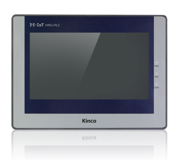
Only the 7-inch devices (MK070E) have LEDs on the front. After power-up, the top LED PWR lights up orange. On the MK043E you see the PLC status in KincoBuilder.
LEDs on the front (MK070E only)
LED State Meaning PWR (orange, top) on Supply OK RUN (green) on PLC running (RUN) RUN (green) flashing PLC in firmware update mode RUN (green) off PLC stopped (STOP) STA (blue) on Error in the user program or in the PLC The manual says PWR is green; on current MK070E units it lights up orange (checked on the device, 29.09.2026).
Older devices have a red LED Err instead of STA; the first series also have Com (flashes during data traffic on Port1/Port2). The meaning is the same.
Show wiring “24 V supply”Show wiring “Supplying the outputs”
Source: Manual ch. 2.2.5.1, 2.2.8.1, 2.2.9, 2.2.10
2Inputs and outputs of the modelsOptional
All models have the same PLC technology, the same software and the same interfaces in the DB9 (2 × RS-485, CAN for up to 8 KS modules). They differ in screen size and inputs and outputs. In the wiring diagram, select your model at the top; it then shows only the matching examples.
The Blank variants only have a neutral front and are technically identical.
Model Inputs Outputs Analog / temperature Special feature MK043E-20DT 9 DI 9 DO (transistor) 2 AI, 0–10 V – MK043E-20DTC 9 DI 9 DO (transistor) 2 thermocouples J/K/E/T – MK043E-27DT 10 DI 10 DO (transistor) 2 AI (current/voltage), 1 AO 4 DIO, COM2 (RS-232), USB-C MK070E-33DT 16 DI 14 DO (transistor) 2 AI (current/voltage), 1 AO – MK070E-32DX 16 DI 12 relays, 4 DO (transistor) – – MK070E-27DRT 12 DI 12 relays 3 Pt100 (2- or 3-wire) – Relay outputs cannot output pulses. For stepper motors and servos via pulse/direction, you need a model with transistor outputs on Q0.0–Q0.7.
According to the manual text, the MK043E-20DT only measures voltage (0–10 V); the connection diagram in ch. 2.2.12 labels the channels “Current input”. We follow the text.
Show wiring “Relay outputs”Show wiring “Pt100 3-wire”Show wiring “Thermocouple on channel A”Show wiring “DIO as input and output”
Source: Manual ch. 1.4, 2.2.10, 2.2.11, 2.2.12
3Two devices, two programsRequired
In the MK, the HMI and PLC work independently of each other and exchange their data via an internal serial connection. That is why you need two programs: KincoBuilder for the PLC and KincoDTools for the operator screen. For remote maintenance via VPN, add the EdgeAccess Viewer.
The ports are permanently assigned: Ethernet belongs to the HMI, the two RS-485 ports and the CAN bus in the DB9 belong to the PLC.
Task Software Connection Program and monitor the PLC, set the PLC clock KincoBuilder (LD/IL) USB slave (virtual COM port) Create and download the operator screen, update the HMI firmware KincoDTools USB slave or Ethernet Remote maintenance of HMI and PLC via VPN EdgeAccess Viewer Internet (Kinco VPN server) Back up your project before switching to a new software version. A project saved with a newer version cannot always be opened in the older one (experience from the forum).
Download KincoBuilderDownload KincoDToolsIn the system menu: Enable VPN
Source: Manual p. 2 (Programming Software Acquisition), ch. 2.2.8.7; spstiger forum: "SPS des Kinco MK über Ethernet programmieren", "Kinco Builder 8.5"
4Connect the PC to the MKRequired
Connect the PC to the USB-Slave socket on the back (USB-B, USB-C on the MK043E-27DT). Use a USB data cable, not a charge-only cable.
Windows then detects two devices: the HMI as a USB device for KincoDTools and the PLC as a virtual COM port, e.g. “Kinco Virtual COM (COM5)”, for KincoBuilder. Device Manager shows the COM port number.
USB slave and USB host share one controller in the device. As long as the PC is connected via USB, no USB stick works, and vice versa. So remove the stick before you program.
Connection in KincoBuilder
Remove the USB stick, plug in the USB cable.
Read the new COM port in Device Manager.
In KincoBuilder, open the communication settings and select Use COM Port, not USB. Then set the COM port.
Click Start: KincoBuilder searches for the PLC and takes over its parameters.
Confirm with OK.
The HMI's USB driver sometimes gets stuck: Windows then reports “Unknown USB device”, or KincoDTools cannot find the HMI. In Device Manager, select “Update driver” and point it to the driver folder in the KincoDTools installation directory (spstiger forum: "Kinco HMI wird per USB nicht erkannt").
You can reach the HMI via Ethernet if your PC is in the same network: with the mask 255.255.255.0, the first three numbers of the IP address match and the last one differs. The PLC can only be programmed via Ethernet with a workaround (virtual COM communication with pass-through in the KincoDTools device manager, spstiger forum: "SPS des Kinco MK über Ethernet programmieren"). To get started, USB is the easier way.
In the system menu: Check the IP address and PC adapter
Source: Manual ch. 4.6.1; spstiger forum: "USB-Stick und USB-Programmieren nicht gleichzeitig", "Verwendung des USB-Programmier-Port"
5Create and download the PLC projectRequired
KincoBuilder remembers the CPU you programmed last and creates new projects with it. After the first installation, a different model is usually set there (according to the manual K606-24DT). So check in the hardware configuration that your MK model is in the first row. If the CPU does not match, KincoBuilder does not download the project.
In the hardware configuration you also define which values the outputs take in STOP. In STOP, the PLC immediately sets all DO and AO to these values, also after a fatal error.
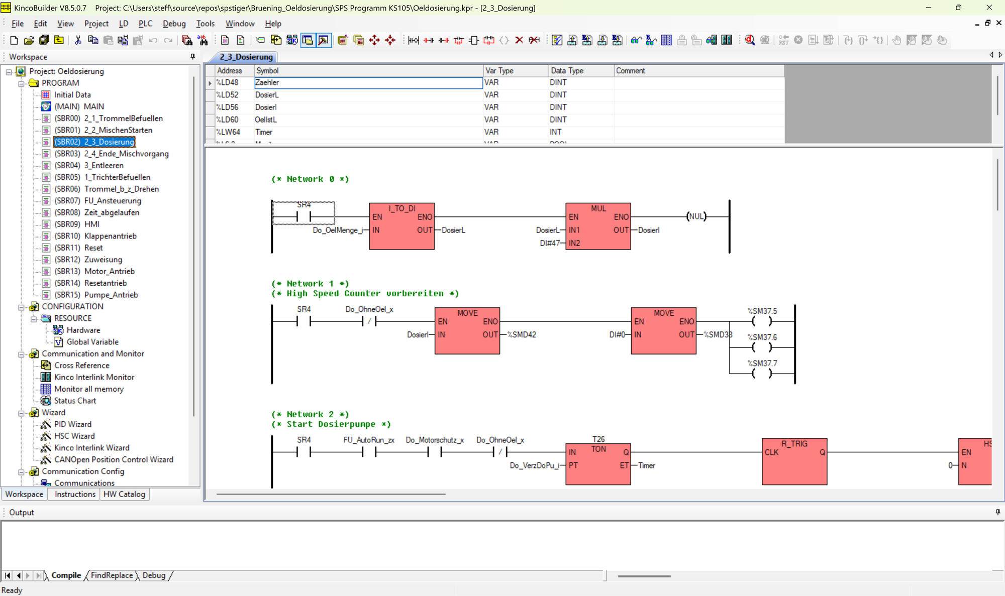
Module I Address Q Address Comment 1 MK070E-33DT DI 0…1, AI 0…3 DO 0…1, AO 0…1 MK070, DI 16*DC24V, DO 14*DC24V, AI 2*IV, AO 1*IV 2 KS121-16DX 2…3 KS121, DI 16*DC24V 3 KS133-06IV 4…11 2…5 KS133, AI*4, AO*2, 4–20mA/0–20mA/1–5V/0–10V Hardware configuration with two KS expansions: the CPU at the top, below it the modules in plug-in order. KincoBuilder assigns the address ranges itself. The first network in ladder diagram: normally open contact %I0.0 switches coil %Q0.0. First program
File › New Project, choose location and name.
In the project tree, double-click Hardware. If the first row does not show your model: delete the CPU with a right-click.
In the HW catalog, double-click your model, e.g. MK070E-33DT. Set the output values for STOP here as well.
Under Reten, switch off the permanent backup area (All of the above areas are Not used), see step “Store setting values retentively”.
Enter KS expansion modules in the same order in which they are wired.
Write a small network, e.g. I0.0 switches Q0.0.
Optionally test in the simulator.
PLC › Download (F8). KincoBuilder compiles automatically beforehand.
Debug › Start PLC, then press F6 for monitoring mode.
You can also set the CPU for new projects permanently under Tools › Options.
Write names of variables, blocks and programs without umlauts and without ß. The software core does not support Unicode; on the device this leads to error 29, even though the simulation runs (spstiger forum: "Fehlermeldung 29").
A project consists of the .kpr file and the folder next to it with the subroutines. Always copy and back up both together (spstiger forum: "HMI+PLC (MK070E) Modbus RTU Master").
Show wiring “PNP devices on DI”Show wiring “Valve and lamp on DO”Show wiring “KS expansion via CAN”Show wiring “Supply and expansion bus”
Source: Manual ch. 2.2.5.1, 4.2, 4.3, 4.6.2
6Create the HMI project and connect it to the PLCRequired
You create the operator screen in KincoDTools. So that the HMI can read and write the data of the built-in PLC, you enter the PLC on COM0. The connection is internal; you do not need to wire anything.
As HMI type, select MK070E for all 7-inch models; from the HMI's point of view, 33DT, 32DX and 27DRT are identical. For the 4.3-inch device there are two types: MK043E for the 20DT and 20DTC, and MK043E-27DT, because on the 27DT the RS-232 interface COM2 can also be configured (DB9: pin 3 RXD, pin 8 TXD, pin 5 GND). The MK2070E in the list is a different device.
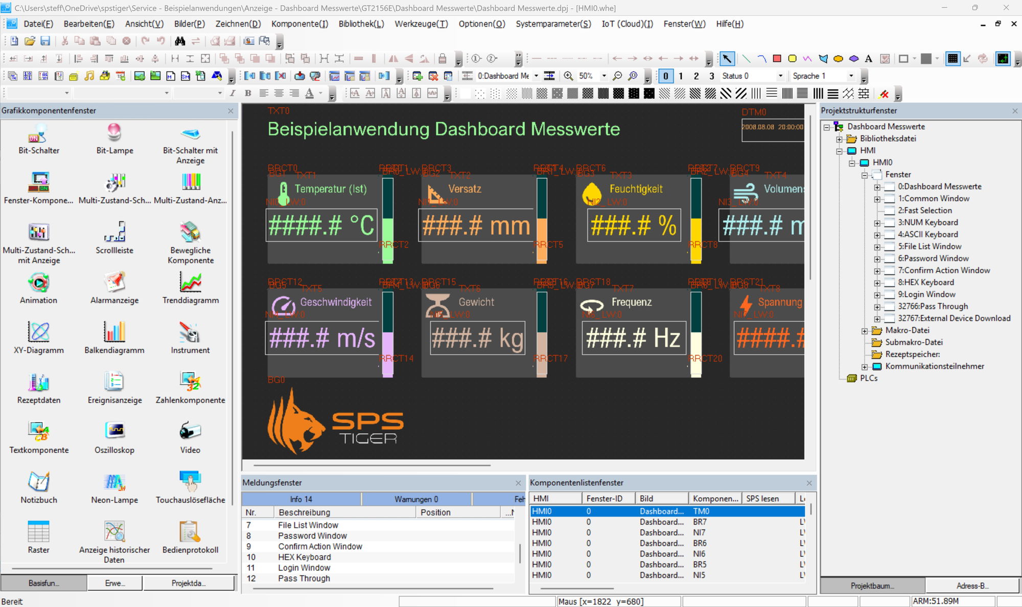
This is how KincoDTools shows the connection: HMI0 is connected via COM0 to PLC_0_1 (Kinco PLC Series), the built-in PLC. Net is the Ethernet interface. The MK043E-27DT adds COM2, to which you can connect another device via RS-232. HMI – PLC connection
File › New, select HMI type MK070E, MK043E or MK043E-27DT.
Open the system parameters, click COM0.
Select manufacturer Kinco, protocol Kinco PLC Series, Add, then Finish.
Under Network Device Setting, enter the HMI's IP address if required.
In the HMI editor, assign a button and a lamp to PLC addresses, e.g. M0.0 and Q0.0.
Test with the offline simulation.
Compile All, then Download. In the download dialog, check the connection (USB or Ethernet).
Never change the download port 21845 in KincoDTools. It has nothing to do with the ports for Modbus TCP (502) or Siemens (102). If you change it, the HMI can no longer be reached for downloads (spstiger forum: "Bitte nie den Port 21845 ändern").
If “Update IP after download” is set in the download dialog, the HMI takes over the IP address from the project. The device may then be reachable at a different address.
In the system menu: IP address of the HMI
Source: Manual ch. 5.1, 5.2, 5.6, 5.9.1; spstiger forum: "MK070E in Dtools mit interner SPS verbinden", "HMI-Gerätetausch auf MK070E-33DT"
7Store setting values retentively⚠ CautionRequired
Do not use the permanent backup area – it can destroy the PLC
In the hardware configuration, KincoBuilder offers a permanent backup area (VB3648–VB3902 or VB3648–VB4095). It is located in the EEPROM, which according to the manual only tolerates 1 million write cycles.
If a variable in it is written cyclically, this limit is reached quickly and the PLC is permanently damaged. Example (calculated): at one write per second, it is over after just under 12 days. We see such failures in support again and again.
Therefore: set the area to All of the above areas are Not used and store setting values only via Reten. If KincoBuilder warns about a limited number of write cycles for V addresses, the area is still active.
Values that your operator sets on the HMI are stored in the PLC, usually in the V area. Without configuration, they are lost after a power failure. In the hardware configuration, you define under Reten which area is retained.
A CR2032 coin cell keeps the data in RAM. It is only drawn on while the device is without power and, according to the manual, lasts at least 3 years without supply. Reading and writing are as fast and as unlimited as with normal variables.
I/OCommRetenLocal AILocal AOCANOpenOthersData Maintain Data Area Start Length Range 1 VB 1000 500 Range 2 VB 0 0 Range 3 C 0 0 Range 4 C 0 0 Up to four retentive areas; here VB1000–VB1499 are retained. Counter values (C) in Range 3 and 4 if required. Set the retentive area
In KincoBuilder, open Hardware, tab Reten.
Enter start address and length. Example: from VB1000, length 500 bytes. VR200, for example, occupies VB200–VB203.
Set the permanent backup area to All of the above areas are Not used.
Download the project. In the download dialog, only set “Clear the Retentive Ranges in V area after downloading” if you really want to delete the stored values.
Memory types of the MK PLC
Memory Range Use Retentive (battery, RAM) V: VB0–VB1907 (max. 1908 bytes), counters C0–C63 Setting values, counter values, everything that changes Permanent backup area (EEPROM) VB3648–VB3902 or VB3648–VB4095 do not use (see warning above) SM0.7 reports the battery status: TRUE = battery voltage low. Ideally, show this bit as a message on the HMI.
Source: Manual ch. 2.2.7.1, 2.2.8.8, 4.6.2; spstiger forum: "Einstellwerte dauerhaft speichern"
9Protect, back up and update the program in the fieldOptional
If you want to prevent anyone from reading out your PLC program, set the option Upload Disabled during download. The program is then stored encrypted and can never be uploaded again. Store your own project safely beforehand.
You can load new programs without a PC via USB stick (FAT32). That saves taking the laptop to the machine.
PLC program via USB stick
Compile the project in KincoBuilder. This creates the file default.obj.
Copy the project folder to a FAT32 stick and plug the stick into USB-Host.
At power-up, press and hold the screen, System Setup › English › File › PLC Project Download.
Select options (upload lock, deletion of the retentive or permanent data) and OK.
Select default.obj. The device restarts after the transfer.
Do not use the CPU password protection in KincoBuilder. If the password is forgotten, the CPU cannot be reset. The upload lock is the better protection (spstiger forum: "Passwortschutz bei Kinco HMI+SPS").
Transferring the HMI project by stick is even easier: put the compiled .pkgx file in the root directory of the stick and plug in the stick. The HMI then asks whether it should load the project (spstiger forum: "Verwendung des USB-Programmier-Port").
The PLC stick download requires HMI firmware from KincoDTools 4.3.0.2. If the menu item is missing in the file manager, update the HMI firmware first.
Source: Manual ch. 4.6.2, 5.9.2; spstiger forum as mentioned
10First run and diagnosticsRequired
Delete the PLC program with the CLR button
Press CLR on the back for about 5 seconds until STA flashes at 2-second intervals.
Release for at least 2 seconds. STA now flashes quickly (600 ms). After 60 seconds without confirmation, the PLC aborts.
To confirm, press CLR again for at least 5 seconds. STA lights up continuously and the program is deleted.
Success: STA flashes twice at 2-second intervals. Failed: four times at 1-second intervals.
Switch the supply off and on again within 60 seconds, otherwise repeat everything.
Common error messages in KincoBuilder
Code Meaning Remedy 20 CPU in the hardware configuration does not match the device Correct the CPU in Hardware; until then KincoBuilder does not download the project 21 Expansion modules in the hardware configuration faulty Compare order and models with the wiring 29 Unknown instructions in the program at power-up Firmware does not match the KincoBuilder version, or umlauts in names Feedback via STA is only available on the MK070E. On the MK043E, carry out the procedure by timing and then check in KincoBuilder whether the program has been deleted (derived; the manual only describes the LED indication).
CLR helps if a program error has sent the PLC into the safety subsystem (RUN off, Err flashing; PLC no longer responding). You can do the same in KincoBuilder via Tools › Clear. SM2.0 defines whether the PLC instead restarts after a fatal error (1) or stops (0, factory default after power-up).
You update the HMI firmware via KincoDTools (device manager). This is uncritical, but deletes the project, recipes and records on the HMI: back them up first. You can only get PLC firmware via our support. The update is risky and only necessary if a new instruction requires it (error 29).
Other error codes are described in the KincoBuilder online help (Help › Contents and Index).
In the system menu: Firmware update mode
Source: Manual ch. 2.2.5.1, 2.2.5.2, 4.7, 4.8; spstiger forum: "SPS-Projekt auf dem Kinco MK über den Button löschen", "Wie mache ich ein Firmware-Update auf dem HMI?", "MK070E [20]Device error"
Revision 2.1 · 29.09.2026 · Source: Kinco MK Series User Manual V001 (04/2025); KincoBuilder help (ch. 6.11); screens and video of an MK070E; practical tips from the spstiger community forum (forum.spstiger.de), cited at each step. The manufacturer manual and applicable standards take precedence; installation and commissioning by a qualified electrician only.
Dimensions and mounting
The MK sits in a cut-out in the control cabinet door or an operator panel and is held from behind by four mounting clips. The dimensions are taken from the manual; the sketches are schematic.
| Housing | Models | W × H × D (mm) | Panel cut-out (mm) | Depth behind panel (mm) |
|---|---|---|---|---|
| MK070E (7 inch) | MK070E-33DT, MK070E-32DX, MK070E-27DRT | 204 × 150 × 34 | 192 × 138 | 27 (calculated) |
| MK043E-20DT / -20DTC (4.3 inch) | MK043E-20DT, MK043E-20DTC | 132 × 102 × 32 | 119 × 93 | 25 (calculated) |
| MK043E-27DT (4.3 inch) | MK043E-27DT | 132 × 102 × 45 | 119 × 93 | 39 (calculated) |
Mounting step by step
1Check the installation site
The MK is designed for installation in control cabinet doors and operator panels. The manual specifies these operating conditions:
Ambient temperature −10 to +55 °C with natural ventilation.
Humidity 10 to 95 %, non-condensing. Pollution degree 2, altitude up to 2000 m.
Degree of protection according to the manual: IP20. It gives no rating for the front; the gasket on the bezel is meant to keep out dust and water (ch. 3.3).
The manual gives no minimum clearances. Keep the ventilation openings on the back free and allow space behind the unit for DB9 connectors, USB and patch cables.
Landscape or portrait orientation is possible; you set the screen orientation accordingly in KincoDTools.
2Mark and cut the panel cut-out
You will find the panel cut-out for your model in the table above: 192 × 138 mm for the MK070E, 119 × 93 mm for all MK043E. The 1:1 cut-out template helps with marking out. Print it at actual size (100 %) and check the 100 mm reference length with a ruler.
The manual gives no tolerance and no permissible panel thickness. Better to cut slightly small and rework than to cut too large. Deburr the edges so the gasket seats properly.
3Insert and clamp
The bag in the box contains four mounting clips with screws (ch. 3.3).
Insert the unit into the cut-out from the front. Do not remove the gasket on the front bezel.
Hook the mounting clips into the square slots on the housing from behind. The MK070E has slots on all four sides; the clips go either top and bottom or left and right.
Tighten the screws clockwise, evenly and crosswise, to 0.5 N·m. Tightening harder deforms the housing; too loose and the front does not seal.
4Unplug and wire the terminal blocks
All terminal blocks are pluggable. You can unplug them and wire them conveniently outside the cabinet (ch. 3.2).
Unplugging: grip the block by the side handles at the top and pull it straight off.
Plugging in: place the guide lugs at the end of the block into the slot and press firmly until it is seated.
The wiring diagram for your model shows which cable goes where.
Revision 1.0 · 29.09.2026 · Source: Kinco MK Series User Manual V001 (04/2025), ch. 1.3, 2.2.4, 2.2.13, 3.2 and 3.3. The manufacturer manual and applicable standards take precedence; installation by a qualified electrician only.
Stuck?
Our support helps you free of charge. Tell us what you are planning and which model you use – via the contact form, by email or in the community forum.
Contact formEmail support@spstiger.deAsk in the community forum
More ways to contact us: Support contacts
We have compiled and checked this page carefully from the manufacturer’s documentation. Even so, an error may have slipped in. The manufacturer’s manual and the applicable standards always take precedence. Spotted something? Let us know – we’ll be glad to fix it.
Downloads
MK series user manual:
Kinco MK series HMI with PLC
Compatible software
Accessories