


Versandkostenfrei innerhalb Deutschlands Professioneller technischer Support

Kinco K6 – Support, Wiring Diagram & Commissioning
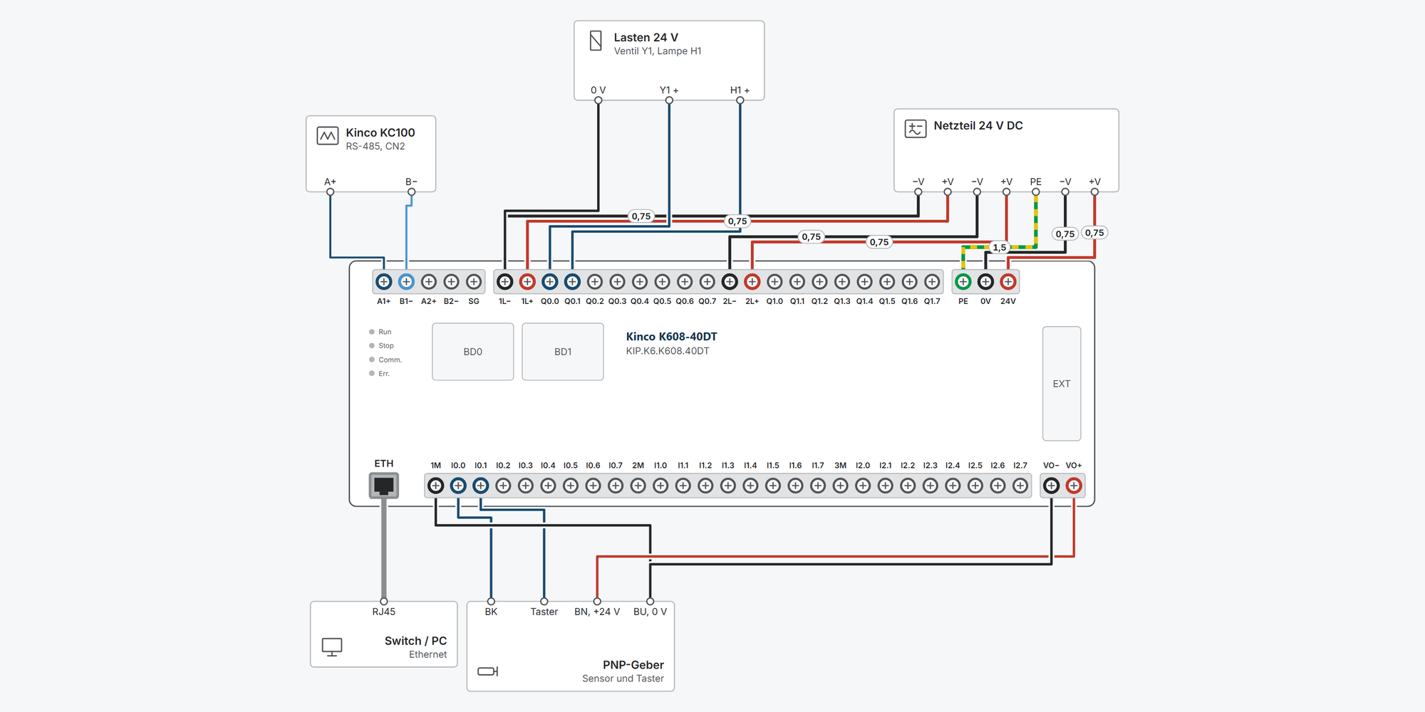
Interaktiver Anschlussplan Kinco K6

Everything for your Kinco K6 after purchase – for the CPUs K606-24, K606EA-30 and K608-40 in all versions:

  • Interactive wiring diagram: power supply 24 V DC and 230 V AC, PNP and NPN sensors, encoder, analog sensors and analog output (K606EA), transistor and relay outputs, pulse output, Modbus RTU and Ethernet, with cable cross-sections and parameters

  • First steps: commissioning in ten steps, from first power-up to your first own program

  • Dimensions & mounting: dimensional drawing per model, drilling pattern, minimum clearances and a printable drilling template

  • Downloads: K6 user manual, dimension drawings (2D and 3D) and wiring diagrams of all CPUs and expansion modules

  • Free support from spstiger if you get stuck

Further down:HelpDownloads

Interactive wiring diagram

Tap a terminal or wire in the drawing to see details.

Terminal overview K6

TerminalGroupmm²Function
A1+RS4850.2–1.5*TXD+/A of the first RS-485 interface. Modbus RTU master/slave, programming protocol, free communication; 1200–115 200 bit/s, galvanically isolated.
B1−RS4850.2–1.5*TXD−/B of the first RS-485 interface.
A2+RS4850.2–1.5*TXD+/A of the second RS-485 interface, same functions as PORT1.
B2−RS4850.2–1.5*TXD−/B of the second RS-485 interface.
SGRS4850.2–1.5*Signal ground of both RS-485 interfaces (manual: Ground).
1L−DO0.2–1.5*Reference of outputs Q0.0–Q0.4, return conductor of the loads.
1L+DO0.2–1.5*+24 V DC for the PNP outputs Q0.0–Q0.4 (20.4–28.8 V).
Q0.0DO0.2–1.5*PNP transistor output (group 1L), max. 500 mA at 24 V DC, short-circuit proof. Fast output: PTO/PWM channel 0 up to 200 kHz.
Q0.1DO0.2–1.5*PNP transistor output (group 1L), max. 500 mA at 24 V DC, short-circuit proof. Fast output: PTO/PWM channel 1 up to 200 kHz.
Q0.2DO0.2–1.5*PNP transistor output (group 1L), max. 500 mA at 24 V DC, short-circuit proof. Direction for PTO channel 0.
Q0.3DO0.2–1.5*PNP transistor output (group 1L), max. 500 mA at 24 V DC, short-circuit proof. Direction for PTO channel 1.
Q0.4DO0.2–1.5*PNP transistor output (group 1L), max. 500 mA at 24 V DC, short-circuit proof. Fast output: PTO/PWM channel 2 up to 200 kHz.
2L−DO0.2–1.5*Reference of outputs Q0.5–Q1.1, return conductor of the loads.
2L+DO0.2–1.5*+24 V DC for the PNP outputs Q0.5–Q1.1 (20.4–28.8 V).
Q0.5DO0.2–1.5*PNP transistor output (group 2L), max. 500 mA at 24 V DC, short-circuit proof. Fast output: PTO/PWM channel 3 up to 10 kHz.
Q0.6DO0.2–1.5*PNP transistor output (group 2L), max. 500 mA at 24 V DC, short-circuit proof. Direction for PTO channel 2.
Q0.7DO0.2–1.5*PNP transistor output (group 2L), max. 500 mA at 24 V DC, short-circuit proof. Direction for PTO channel 3.
Q1.0DO0.2–1.5*PNP transistor output (group 2L), max. 500 mA at 24 V DC, short-circuit proof.
Q1.1DO0.2–1.5*PNP transistor output (group 2L), max. 500 mA at 24 V DC, short-circuit proof.
PEPWR0.2–1.5*Marked with the earth symbol on the device. Connect to earth or the protective conductor.
0VPWR0.2–1.5*Reference of the 24 V supply.
24VPWR0.2–1.5*24 V DC ±20 %, reverse polarity and short-circuit protected. Power consumption {pwrDC}.
1MDI0.2–1.5*For I0.0–I0.7. PNP devices (sourcing): 1M to 0 V. NPN devices (sinking): 1M to +24 V.
I0.0DI0.2–1.5*Digital input 24 V DC, PNP or NPN, 3.5 mA. Fast input: HSC0 track B, reset (mode 1/2/4), interrupt.
I0.1DI0.2–1.5*Digital input 24 V DC, PNP or NPN, 3.5 mA. Fast input: HSC0 clock or track A, interrupt.
I0.2DI0.2–1.5*Digital input 24 V DC, PNP or NPN, 3.5 mA. Fast input: HSC1 track B or direction (mode 3/4), interrupt.
I0.3DI0.2–1.5*Digital input 24 V DC, PNP or NPN, 3.5 mA. Fast input: HSC1 clock or track A, interrupt.
I0.4DI0.2–1.5*Digital input 24 V DC, PNP or NPN, 3.5 mA. Fast input: HSC2 clock or track B, HSC1 reset.
I0.5DI0.2–1.5*Digital input 24 V DC, PNP or NPN, 3.5 mA. Fast input: HSC2 track A, HSC0 start or direction (mode 2–4).
I0.6DI0.2–1.5*Digital input 24 V DC, PNP or NPN, 3.5 mA. Fast input: HSC3 clock or track B, HSC1 start.
I0.7DI0.2–1.5*Digital input 24 V DC, PNP or NPN, 3.5 mA. Fast input: HSC3 track A.
2MDI0.2–1.5*For I1.0–I1.5. PNP devices (sourcing): 2M to 0 V. NPN devices (sinking): 2M to +24 V.
I1.0DI0.2–1.5*Digital input 24 V DC, PNP or NPN, 3.5 mA.
I1.1DI0.2–1.5*Digital input 24 V DC, PNP or NPN, 3.5 mA.
I1.2DI0.2–1.5*Digital input 24 V DC, PNP or NPN, 3.5 mA.
I1.3DI0.2–1.5*Digital input 24 V DC, PNP or NPN, 3.5 mA.
I1.4DI0.2–1.5*Digital input 24 V DC, PNP or NPN, 3.5 mA.
I1.5DI0.2–1.5*Digital input 24 V DC, PNP or NPN, 3.5 mA.
VO−VO0.2–1.5*Reference of the built-in 24 V source.
VO+VO0.2–1.5*Built-in 24 V DC source for sensors and field devices, max. {voI}. Do not connect in parallel with an external power supply.
ETHETH–10/100 Mbit/s, auto-negotiation. Programming, Modbus TCP client/server, free TCP/UDP, firmware update. Factory IP 192.168.0.252.

* Clamping range not stated in the manual, derived.

Getting started with the Kinco K6

The K6 is a compact PLC with Ethernet, two RS-485 interfaces and slots for BD cards. This guide applies to the K606-24, K606EA-30 and K608-40 CPUs and takes you from first power-up to your first own program: supply, connect via Ethernet, create and download a project in KincoBuilder, store values retentively. You need expansions, the clock, program protection and diagnostics as soon as the machine grows or is in operation.

Before connecting
  • Check the rating plate: models with D before the output type (…DT, …DR) need 24 V DC (±20 %). Models with A (K606-24AR, K608-40AR) are supplied directly with 100–240 V AC.

  • Connect the earth terminal (earth symbol next to the supply) to PE.

  • Only wire and plug in BD cards with the supply switched off.

  • Route control and communication cables at least 100 mm away from power cables.

  • Do not use the permanent backup area for values that change often. The EEPROM only tolerates 1 million write cycles (see step “Store data retentively”).

  1. 1Power supply and first startRequired

    DC units: 24 V to 24V, minus to 0V. AC units: L and N. On both, connect the earth terminal to PE.

    Transistor outputs (…DT) need their own supply per group: 1L+/1L− and 2L+/2L−. Relay outputs (…DR, …AR) switch whatever you connect to their common terminal 1L, 2L …, 24 V DC or 230 V AC.

    The CPU has a built-in 24 V output VO+/VO− for encoders and field devices. It supplies max. 300 mA on the K606 and on DC units, max. 500 mA on the K608-40AR.

    You can also switch between RUN and STOP without a PC: the switch is located in slot BD0 under the cover. Remove the cover and slide the switch to the RUN or STOP side.

    Status LEDs on the front

    LEDStateMeaning
    Run (green)onPLC running (RUN)
    Run (green)flashingFirmware update mode
    Stop (red)onPLC stopped (STOP)
    Comm. (green)flashingData traffic on PORT1/PORT2
    Err. (red)onError in the program or in the CPU, details in KincoBuilder

    In one place the manual gives 500 mA for the 24 V output for all CPUs (ch. 2.2.3.10), in the table in appendix 8.2 300 mA (K606 and DC units) or 500 mA (AC units K606EA/K608). We state the lower value here.

    If the CPU detects a fatal error during operation, it goes to STOP by itself.

    Show wiring “Supply 24 V DC”Show wiring “Supply 230 V AC”Show wiring “Supplying the outputs”

    Source: Manual ch. 2.2.3.1, 2.2.3.10, 3.1.3, 3.1.4, appendix 8.2

  2. 2Inputs and outputs of the modelsOptional

    All inputs are 24 V inputs for PNP or NPN sensors, in groups via 1M, 2M, 3M. The K606EA only has group 1M. Transistor outputs switch PNP (positive switching), max. 500 mA per output. Relay outputs switch 2 A per contact, max. 8 A per group.

    High-speed counters and pulse outputs are on the same terminals on all CPUs: counters on I0.0–I0.7 (HSC0/HSC1 up to 200 kHz), pulses on Q0.0, Q0.1, Q0.4 (up to 200 kHz) and Q0.5 (10 kHz), direction on Q0.2, Q0.3, Q0.6, Q0.7. Relay CPUs cannot output pulses.

    CPUSupplyDIDOAnalogBD slots
    K606-24DT24 V DC1410 transistor–1
    K606-24DR24 V DC1410 relay–1
    K606-24AR100–240 V AC1410 relay–1
    K606EA-30DT24 V DC1410 transistor4 AI, 2 AO2
    K608-40DT24 V DC2416 transistor–2
    K608-40DR24 V DC2416 relay–2
    K608-40AR100–240 V AC2416 relay–2

    The analog channels of the K606EA measure 4–20 mA, 0–20 mA, 1–5 V or 0–10 V (12 bit, 0.3 %). For current, switch in the measuring resistor: connect R* to *+.

    All CPUs have 2 × RS-485 (PORT1, PORT2) and 1 × Ethernet, program memory 8k instructions, V area 16 KB.

    Show wiring “PNP devices on DI”Show wiring “NPN devices on DI”Show wiring “Encoder on HSC0 (A/B)”Show wiring “Sensor 2-wire 4–20 mA”

    Source: Manual ch. 1.4, 2.2.3.7, 2.2.3.8, 2.2.4

  3. 3Install KincoBuilderRequired

    The K6 is programmed with KincoBuilder in ladder diagram (LD) or instruction list (IL) according to IEC 61131-3. The software is free of charge and includes a simulator you can use to test programs without a PLC.

    You can connect via Ethernet (recommended) or via one of the two RS-485 ports with a USB-RS-485 adapter. Both are suitable for programming and monitoring; the firmware update runs via Ethernet.

    Back up your project before switching to a new software version. A project saved with a newer version cannot always be opened in the older one (experience from the forum).

    New instructions sometimes need matching firmware in the CPU. If the two do not match, the CPU reports error 29 (see step “First run and diagnostics”).

    Download KincoBuilder

    Source: Manual p. II (Programming Software Acquisition), ch. 6.1, 6.4, 6.5; spstiger forum: "Kinco Builder 8.5"

  4. 4Connect the PC via EthernetRequired

    Ex works, the K6 is set to the IP address 192.168.0.252. KincoBuilder can only reach the CPU in the same network. So give your PC an address such as 192.168.0.10 with the mask 255.255.255.0: the first three numbers are the same, the last one differs.

    Alternatively, leave the PC address as it is and change the IP address of the CPU found directly in KincoBuilder. According to the manual, this also works across network boundaries.

    Connection in KincoBuilder

    1. Connect the PC and CPU with a patch cable (directly or via a switch), switch on the CPU.

    2. In the project tree, double-click Double click scan Ethernet or select Tools › Communications › Scan Net.

    3. Select the CPU found with right-click › Communicate with.

    4. If KincoBuilder shows a warning, set Use TCP or Use UDP under Communications and repeat.

    5. If the scan finds nothing: under Communications › Adaptor, select the network card the CPU is connected to and search again.

    Via RS-485: adapter to A1+/B1− (PORT1) or A2+/B2− (PORT2), select Use COM Port in Communications, enter the COM port from Device Manager and click Start. KincoBuilder then takes over the parameters of the CPU.

    You set the PC address in Windows under Network Connections › Adapter › Properties › Internet Protocol Version 4 (TCP/IPv4). Change it back afterwards for the company network.

    Show wiring “Ethernet”Show wiring “Modbus RTU on PORT1”

    Source: Manual ch. 2.2.3.3, 6.6.1

  5. 5Create and download a projectRequired

    KincoBuilder creates a new project with a preset CPU, according to the manual K606-24DT. So check in the hardware configuration that your model is in the first row. If the CPU does not match, the PLC reports error 20.

    In the hardware configuration you also define which values the outputs take in STOP. In STOP, the CPU immediately outputs these values.

    KincoBuilder › MAIN (LD)
    (* Network 0 *)%I0.0%Q0.0
    The first network in ladder diagram: normally open contact %I0.0 switches coil %Q0.0.

    First program

    1. File › New Project, choose location and name.

    2. In the project tree, double-click Hardware. If the first row does not show your model: delete the CPU with a right-click.

    3. In the HW Catalog, double-click your model, e.g. K608-40DT. Set the output values for STOP here too.

    4. Enter BD cards and expansion modules, see step “Expansions and BD cards”.

    5. Write a small network, e.g. I0.0 switches Q0.0.

    6. Project › Compile All (F7). Errors are listed in the Output window; double-click jumps to the location.

    7. Optionally test in the simulator.

    8. PLC › Download (F8). KincoBuilder compiles automatically beforehand.

    9. Debug › Start PLC (or switch to RUN), then press F6 for monitoring mode.

    You can set the CPU for new projects permanently under Tools › Options.

    Write names of variables, blocks and programs without umlauts and without ß. The software core does not support Unicode; on the device this leads to error 29, even though the simulation runs (spstiger forum: "Fehlermeldung 29").

    A project consists of the .kpr file and the folder next to it with the subroutines. Always copy and back up both together (spstiger forum: "HMI+PLC (MK070E) Modbus RTU Master").

    Help on any instruction: select the instruction and press F1.

    Show wiring “PNP devices on DI”Show wiring “Valve and lamp on DO”

    Source: Manual ch. 2.2.3.1, 6.2, 6.3.1, 6.4, 6.5, 6.6.2

  6. 6Expansions and BD cardsOptional

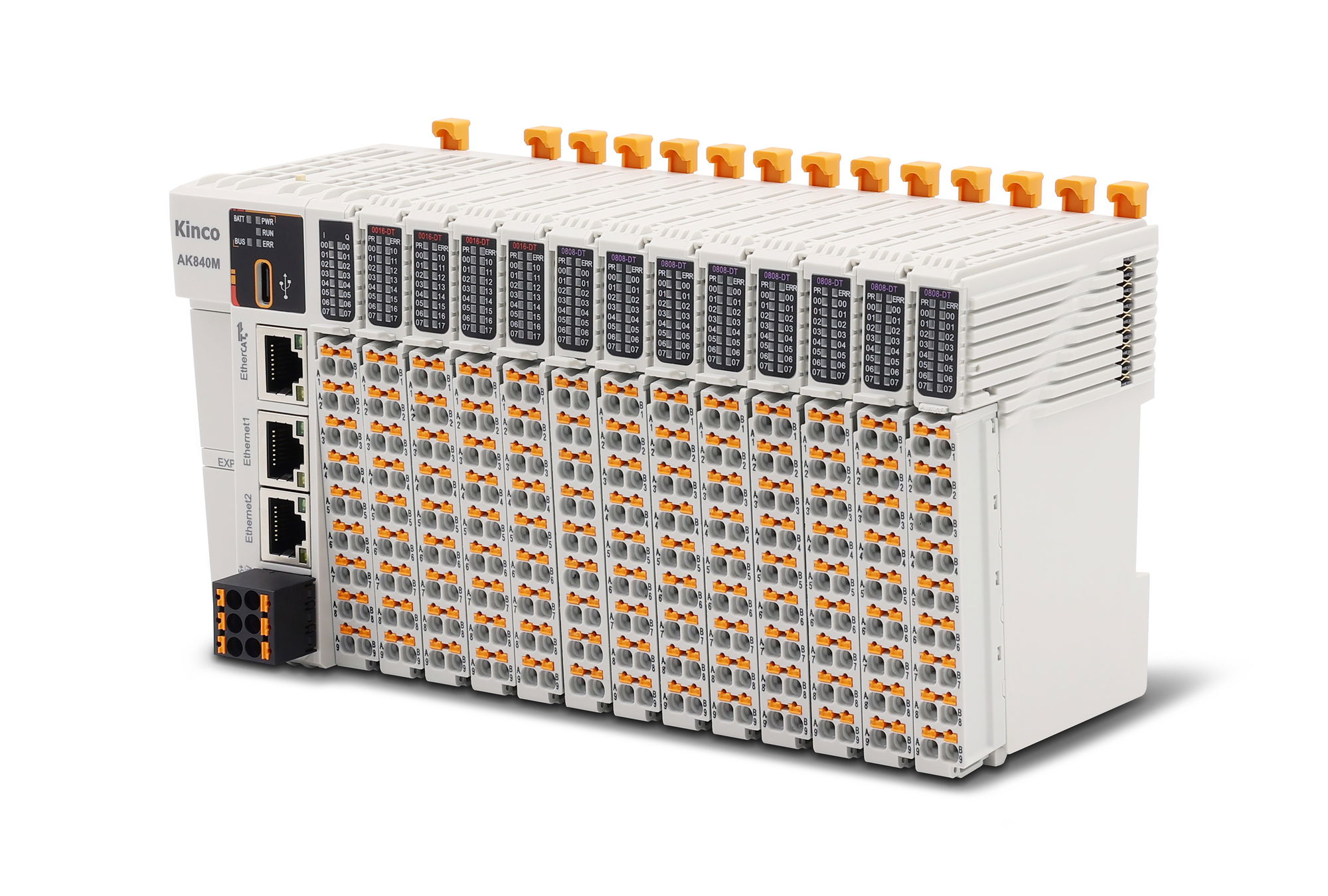
    Up to 14 expansion modules fit to the right of the CPU (K6 modules, according to the manual also K5 modules). The modules are connected from left to right with the supplied ribbon cable; the CPU is always on the far left. In KincoBuilder you enter them under Hardware in exactly this order, otherwise the PLC reports error 21.

    BD cards plug into the front of the CPU, under the cover: the K606 has one slot (BD0), the K606EA and K608 have two (BD0, BD1). Communication cards (KB6-CAN, KB6-2COM) only fit in BD0, I/O cards (KB6-4DI, KB6-4DO) in both.

    Install modules and cards

    1. Switch off the supply.

    2. Place the modules on the DIN rail, only then plug in the ribbon cables (otherwise the interface can break).

    3. Plug the cable from the output of the left module into the input of the right one, push the modules close together, close the covers.

    4. With many modules or more than 0.5 m bus length, connect pin 9 and 10 of the expansion interface on the last module with a short wire jumper.

    5. Remove the cover and plug the BD card into BD0 or BD1.

    6. In KincoBuilder under Hardware, enter the modules in plug-in order and the BD cards in the matching slot.

    Current consumption on the expansion bus (examples from the manual)

    Module+5 V+24 V (relay coils)
    CPU supplies (all K6)1500 mA360 mA
    K680 supplies in addition1000 mA250 mA
    K621-16DX (16 DI)210 mA–
    K622-16XR (16 relays)210 mA120 mA
    K623-16DR (8 DI, 8 relays)210 mA60 mA
    K631-04IV (4 AI)172 mA– (10 mA external)
    K633-04IV (2 AI, 2 AO)166 mA– (10 mA external)

    If the CPU's current is not sufficient, insert the K680 power supply module in between or use a second CPU. Calculation example in the manual, appendix 8.5.

    If a BD card is plugged in but not configured, the CPU uses default values: KB6-4DI at IB30 (BD0) or IB31 (BD1), KB6-4DO at QB30 or QB31; KB6-2COM with PORT0 and PORT3 as Modbus RTU slave, address 1, 9600 bit/s, 8N1; KB6-CAN with 500 kbit/s.

    The KB6-CAN has a switchable 120 Ω termination (switch ON). It turns the K6 into a CANopen master for up to 64 nodes, e.g. Kinco servos.

    KB6-CANKB6-2COMK680 power supply module

    Source: Manual ch. 2.2.3.2, 2.2.3.4, 5.1, 5.2, 6.3.2, 6.3.3, appendix 8.3

  7. 7Store data retentively⚠ CautionRequired

    Setting values and counter values are usually stored in the V area. Without configuration, they are lost after switching off. In the hardware configuration, you define under Reten which area is retained: up to 16 KB in the V area and the counters (C area).

    A CR2032 coin cell keeps this data in RAM. According to the manual, it lasts at least 3 years without supply. Reading and writing are as fast and as unlimited as with normal variables.

    KincoBuilder › Hardware › Reten
    I/OCommRetenOthers
    Data MaintainData AreaStartLength
    Range 1VB1000500
    Range 2VB00
    Range 3C00
    Simplified view: here VB1000–VB1499 are retained. Counter values (C) in another range if required.

    Set the retentive area

    1. In KincoBuilder, open Hardware, tab Reten.

    2. Enter data area, start address and length. Example: VB from 1000, length 500 bytes. VR200, for example, occupies VB200–VB203.

    3. In the Others tab, set the permanent area to All of the above areas are NOT used if you do not need it.

    4. Download the project. In the download dialog, only set “Clear the Retentive Ranges in V area after downloading” if you really want to delete the stored values.

    Memory types of the K6

    MemoryRangeUse
    Retentive (battery, RAM)V area up to 16 KB, C area 512 bytes, set under RetenSetting values, counter values, everything that changes
    Permanent (EEPROM)VB3648–VB4095 and/or VB15360–VB16383, under Othersonly for values that rarely change

    SM0.7 reports the battery status: TRUE = battery voltage low. Ideally, output this bit as a message, e.g. on an operator panel.

    The options in the Others tab: compatible with K3 (VB3648–VB3902), with K5 (VB3648–VB4095), with K6 (VB15360–VB16383), both areas together or none.

    Source: Manual ch. 2.2.3.5, 2.2.4.8, 6.6.2; spstiger forum: "Einstellwerte dauerhaft speichern"

  8. 8Clock and batteryOptional

    The K6 has a real-time clock that runs on the coin cell when the supply is switched off. On first use, set it with an active connection in KincoBuilder under PLC › Adjust CPU Clock….

    In the program, READ_RTC, SET_RTC, RTC_R and RTC_W read and write the clock. READ_RTC returns BCD values; RTC_R returns decimal values with FMT = 0 (FMT = 1 = BCD).

    Replace the battery (CR2032, 3 V)

    1. Switch off the supply. Retentive data is lost during the replacement if it has not been backed up (derived).

    2. Release the latches on both sides with a small screwdriver and remove the cover.

    3. Remove the silicone adhesive on the battery, lever the battery out at the bottom left.

    4. Insert the new battery into the holder on the right first, then press it in; secure it again with silicone on the left.

    5. Dispose of the old lithium battery according to local regulations.

    The battery typically lasts 5 years, at least 3 years without supply. If it is weak, KincoBuilder reports this under PLC Information › General Errors, in the program SM0.7 = TRUE.

    According to the manual, the clock deviates by less than 5 minutes per month (25 °C).

    Daylight saving time: if Windows changes the clock automatically, the KincoBuilder help says to also set “Using Daylight Saving Time” when setting the CPU clock.

    Source: Manual ch. 2.2.3.6, 2.2.4.8; KincoBuilder help ch. 6.11

  9. 9Protect and back up the programOptional

    If you want to prevent anyone from reading out your program, set the option Set the CPU to “Upload Disabled” during download. The program is then stored encrypted and can never be uploaded again. Store your own project safely beforehand.

    You get a program from the CPU with PLC › Upload. With an unstable connection or large projects, use the variant Upload (breakpoint resume); it continues after an interruption. The same exists for the download.

    Options in the download dialog

    OptionEffect
    Set the CPU to “Upload Disabled”Program encrypted, upload no longer possible
    Clear the Retentive Ranges in V area after downloadingdeletes the retentive data (V and C area)
    Clear the Permanent Backup Ranges after downloadingdeletes the permanent area in the EEPROM
    Not automatically compiled before downloadingnot recommended, only applies until KincoBuilder is restarted

    Do not use the CPU password protection in KincoBuilder. If the password is forgotten, the CPU cannot be reset. The upload lock is the better protection (spstiger forum: "Passwortschutz bei Kinco HMI+SPS").

    Source: Manual ch. 6.6.2; spstiger forum as mentioned

  10. 10First run and diagnosticsRequired

    Firmware update via Ethernet

    1. Only necessary if a new instruction requires it (error 29). You can get the firmware file from our support.

    2. Connect the CPU via Ethernet, open Tools › PLC Firmware Upgrade (Common)… in KincoBuilder and read the help in the window.

    3. Set Communications…, then Select Firmware File… and choose the file. The matching model and versions appear under File Information.

    4. Enter Upgrade Mode: after about 2 seconds, Run flashes quickly.

    5. Start Upgrading: the CPU erases, writes and verifies the memory; the progress is shown at the bottom of the window.

    6. After the success message, restart the CPU.

    Error patterns on the LEDs and in KincoBuilder

    Indication or codeMeaningRemedy
    Run off, Stop on, Err. flashingfatal error, CPU in the safety subsystemin KincoBuilder Tools › Clear (for fatal errors only)
    Run off, Stop on, Err. onserious error, program stops runningView the error in KincoBuilder under PLC Information
    Run on, Err. ongeneral error, program keeps runningView the error in KincoBuilder
    20CPU in the hardware configuration does not match the deviceCorrect the CPU under Hardware
    21Expansion modules in the hardware configuration faultyCompare order and models with the actual setup
    29unknown instructions in the program at power-upFirmware does not match the KincoBuilder version, or umlauts in names

    If the update aborts and Run keeps flashing, click Start Upgrading again. If the CPU can be connected after a restart but cannot be put into update mode, leave it switched off for a while and try again.

    SM2.0 defines whether the CPU restarts after a fatal error (1) or stays in the safety subsystem (0, factory default after power-up). Communication may fail in the safety subsystem.

    Other error codes are described in the KincoBuilder online help (Help › Contents and Index).

    Source: Manual ch. 2.2.3.1, 6.7, 6.8

Revision 1.0 · 29.09.2026 · Source: Kinco K6-Series PLC User Manual (03/2024); KincoBuilder help; practical tips from the spstiger community forum (forum.spstiger.de) on KincoBuilder, cited at each step. The manufacturer manual and applicable standards take precedence; installation and commissioning by a qualified electrician only.

Dimensions and mounting

The K6 mounts on a 35 mm DIN rail or with two M4 screws. The drawing follows Kinco's dimensional drawings; the drilling pattern is available as a printable template.

All models

ItemRatingW × H × D (mm)Hole spacing (mm)Hole ⌀ (mm)Weight (kg)
KIP.K606.24DTK606-24DT · 24 V DC, 14 DI, 10 DO transistor128 × 94 × 762 holes in mounting lugs, top left and bottom right: 118 × 104 (measured from the Kinco drawing)M4–
KIP.K606.24DRK606-24DR · 24 V DC, 14 DI, 10 DO relay
KIP.K606.24ARK606-24AR · 100–240 V AC, 14 DI, 10 DO relay
KIP.K6.K608.40DTK608-40DT · 24 V DC, 24 DI, 16 DO transistor186 × 94 × 732 holes in mounting lugs, top left and bottom right: 176 × 104M4–
KIP.K6.K608.40DRK608-40DR · 24 V DC, 24 DI, 16 DO relay
KIP.K6.K608.40ARK608-40AR · 100–240 V AC, 24 DI, 16 DO relay
KIP.K6.K606.EA.30DTK606EA-30DT · 24 V DC, 14 DI, 10 DO, 4 AI, 2 AO

Mounting step by step

  1. 1Installation site and space requirement

    The K6 is an open device (IP20) for the control cabinet: −10 to 55 °C, 10–95 % humidity non-condensing, up to 2000 m altitude, pollution degree 2.

    Leave at least 60 mm free above and below the devices and allow at least 100 mm mounting depth. When mounted vertically, the permissible ambient temperature drops by 10 K.

    • Width of the row = sum of the housing widths, because the modules butt directly against each other. Example: K608 (186 mm) with two digital modules (75 mm each) = 336 mm (calculated).

    • Route control cables at least 100 mm away from power cables; don't let chips or wire ends fall into the ventilation slots.

    Show clearances in the drawing

  2. 2Mount on the DIN rail

    The units fit 35 mm DIN rails (7.5 or 15 mm high). When mounted horizontally, the CPU is on the left; when mounted vertically, at the top.

    • Pull the sliding latch at the bottom of the unit downwards (unlock).

    • Hook the unit into the rail at the top and press it on at the bottom.

    • Mount all modules this way and slide them next to each other, only then plug in the ribbon cables of the expansion interface. Otherwise the interface can be damaged.

    • Push the modules close together, press the latches upwards (lock).

  3. 3Alternatively with M4 screws

    Each device has two mounting lugs for M4 screws, top left and bottom right. The holes are 5 mm inside the side edges and 5 mm above or below the housing; vertically they are 104 mm apart on all K6 devices.

    The drilling template above is available for each CPU, to print at actual size.

    • Horizontal hole spacing: K606 118 mm (measured), K606EA/K608 176 mm, digital modules 65 mm, analog modules 40 mm.

    • Drill the holes according to the layout plan, CPU on the left or at the top. In a row, each module starts right at the edge of the previous one.

    • Screw the units on one after the other; use a spring washer and flat washer to prevent loosening due to vibration.

    • Plug in the ribbon cables of the expansion interface and place them in the cable duct on the left of the module.

    Show drilling pattern in the drawing

  4. 4Dimensions of the expansion modules

    The expansion modules have the same height (94 mm), depth (73 mm) and vertical hole spacing (104 mm) as the CPUs. So all mounting holes of a row lie on two lines.

    • Digital modules K621, K622, K623 and power supply K680: 75 × 94 × 73 mm, holes 65 × 104 mm.

    • Analog and temperature modules K631, K632, K633: 50 × 94 × 73 mm, holes 40 × 104 mm.

    • According to the manual, K5 expansion modules fit as well; their dimensions are in the K5 manual.

  5. 5Terminal blocks and wiring

    The screw terminal blocks can be unplugged, which makes wiring and replacing units easier. The pin assignment is printed under the flap.

    • Unplugging: open the flap, place a screwdriver vertically in the notch in the middle of the block and lever the block outwards.

    • Plugging in: place the lug at the back of the block into the holder, align the pins and press the block in flush.

    • Tighten the terminal screws to the correct torque; the manual does not state a value.

    Show wiring “Supply 24 V DC”Show wiring “Supplying the outputs”

Revision 2.0 · 30.09.2026 · Source: Kinco K6-Series PLC User Manual (03/2024), ch. 4 and 5; Kinco dimensional drawings K606, K608/K606EA and expansion modules (2023). The manufacturer manual and applicable standards take precedence; installation by a qualified electrician only.

Stuck?

Our support helps you free of charge. Tell us what you are planning and which model you use – via the contact form, by email or in the community forum.

More ways to contact us: Support contacts

Downloads

K6 user manual, dimension drawings (2D and 3D) and wiring diagrams of all CPUs and expansion modules:

Kinco K6 — series documents
Manual, 2D dimension drawings (DWG/PDF), 3D models (STEP) and all wiring diagrams for the Kinco K6 series. The wiring diagram of each device is also attached to the individual model.

Kinco K6 PLC

Kinco K6 PLC K606-24DT with 24 V DC-10 transistor
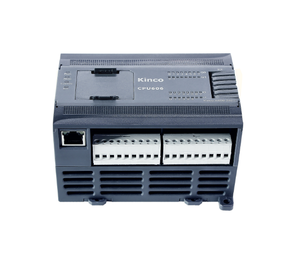
You need a controller for a machine with a manageable number of signals and want to expand later without replacing the PLC? The Kinco K606-24 comes with 14 digital inputs, 10 outputs, Ethernet and two galvanically isolated RS-485 ports, and grows with your system via one BD slot and up to 14 expansion modules. 🏭 Typical applications Conveying and packaging: belts, diverters and feeders. The high-speed counters read encoders up to 200 kHz directly on the device. Positioning with stepper or servo drives: the transistor variants output pulse and direction on four channels, three of them up to 200 kHz. Pumps, fans and frequency inverters: control drives and meters directly via Modbus RTU on RS-485. Connection to HMI and control system: Modbus TCP via Ethernet, for example to a Kinco HMI or a higher-level SCADA. ⚙️ Four variants K606-24DT: 24 V DC supply, 10 PNP transistor outputs K606-24AT: 100 – 240 V AC supply, 10 PNP transistor outputs K606-24DR: 24 V DC supply, 10 relay outputs K606-24AR: 100 – 240 V AC supply, 10 relay outputs 💡 The relay variants have no pulse outputs. For positioning tasks, choose DT or AT. ⚡ Inputs and outputs 14 digital inputs 24 V DC, wired as PNP or NPN, optically isolated, input delay below 40 µs (high-speed channels below 5 µs). PNP transistor outputs: 500 mA per channel at 24 V DC, protected against short circuit, inductive loads and reverse polarity. Relay outputs: 2 A per contact at 30 V DC or 250 V AC, max. 8 A per group of 4 channels, electrical life 100 000 operations at rated load. High-speed counters: 4 channels, HSC0 and HSC1 up to 200 kHz, HSC2 and HSC3 up to 20 kHz single-phase or 10 kHz A/B. 4 edge interrupts on I0.0 to I0.3. Pulse outputs (transistor variants only): 4 channels for PTO (pulse/direction) and PWM, PTO0 to PTO2 up to 200 kHz, PTO3 up to 10 kHz. Positioning instructions and a follow function are included in KincoBuilder. 🔌 Communication Ethernet 10/100 Mbit/s: Modbus TCP client and server, free communication via TCP and UDP, program upload/download and firmware update over the network. 2 × RS-485, galvanically isolated: 1200 to 115 200 bit/s, Modbus RTU master or slave, free protocol and programming on both ports. Up to 32 devices per port. 🧩 Expansion One BD slot takes an expansion board directly on the CPU: KB6-CAN (CANopen master), KB6-2COM (RS-232 + RS-485), KB6-4DI or KB6-4DO. On top, up to 14 expansion modules connect to the local bus. The CPU supplies them with up to 1500 mA at 5 V and 360 mA at 24 V. From about 7 modules, or when the current budget runs out, you add the K680 power supply to the module row. 💻 Programming and memory You program the controller with KincoBuilder (IEC 61131-3) in ladder diagram (LD) or instruction list (IL), version V8.5.0.3 or later. The CPU offers 8k instructions of program memory and 20 kB of data memory (16 kB V area, 4 kB M area). 1000 standard instructions execute in 0.3 ms. On top come 256 timers, 256 counters, arrays with up to 1024 elements and a battery-backed real-time clock (deviation below 5 min per month at 25 °C). The V area and counter values are retained on power loss, and the battery is replaceable. 🔗 Compatible with Kinco K5 Terminal layout and power connection match the K5 series, existing K5 programs run without changes, and K5 expansion modules plug in directly. This lets you replace a K5 in the cabinet without rewiring or reprogramming. 🏷️ Manufacturer and standards Kinco Automation, based in Shanghai and Shenzhen, develops controllers, HMIs and drive technology for international machine builders. The K606-24 is CE marked (EN IEC 61000-6-2:2019, EN IEC 61000-6-4:2019) and tested to GB/T 15969.3-2007, which is equivalent to IEC 61131-2:2007. Protection class IP20, operation from −10 °C to +55 °C, 10 % – 95 % relative humidity without condensation, altitude up to 2000 m. 🔧 Mounting On 35 mm DIN rail or with M4 screws on the mounting plate. Dimensions 128 mm × 114 mm × 76 mm, the terminal blocks are pluggable.
Digital Outputs (Quantity & Type)
Nominal Supply Voltage
From €103.80 *

Preis exkl. MwSt., zzgl. Versandkosten

Kinco K6 PLC K606-24DR with 24 V DC-10 relay
You need a controller for a machine with a manageable number of signals and want to expand later without replacing the PLC? The Kinco K606-24 comes with 14 digital inputs, 10 outputs, Ethernet and two galvanically isolated RS-485 ports, and grows with your system via one BD slot and up to 14 expansion modules. 🏭 Typical applications Conveying and packaging: belts, diverters and feeders. The high-speed counters read encoders up to 200 kHz directly on the device. Positioning with stepper or servo drives: the transistor variants output pulse and direction on four channels, three of them up to 200 kHz. Pumps, fans and frequency inverters: control drives and meters directly via Modbus RTU on RS-485. Connection to HMI and control system: Modbus TCP via Ethernet, for example to a Kinco HMI or a higher-level SCADA. ⚙️ Four variants K606-24DT: 24 V DC supply, 10 PNP transistor outputs K606-24AT: 100 – 240 V AC supply, 10 PNP transistor outputs K606-24DR: 24 V DC supply, 10 relay outputs K606-24AR: 100 – 240 V AC supply, 10 relay outputs 💡 The relay variants have no pulse outputs. For positioning tasks, choose DT or AT. ⚡ Inputs and outputs 14 digital inputs 24 V DC, wired as PNP or NPN, optically isolated, input delay below 40 µs (high-speed channels below 5 µs). PNP transistor outputs: 500 mA per channel at 24 V DC, protected against short circuit, inductive loads and reverse polarity. Relay outputs: 2 A per contact at 30 V DC or 250 V AC, max. 8 A per group of 4 channels, electrical life 100 000 operations at rated load. High-speed counters: 4 channels, HSC0 and HSC1 up to 200 kHz, HSC2 and HSC3 up to 20 kHz single-phase or 10 kHz A/B. 4 edge interrupts on I0.0 to I0.3. Pulse outputs (transistor variants only): 4 channels for PTO (pulse/direction) and PWM, PTO0 to PTO2 up to 200 kHz, PTO3 up to 10 kHz. Positioning instructions and a follow function are included in KincoBuilder. 🔌 Communication Ethernet 10/100 Mbit/s: Modbus TCP client and server, free communication via TCP and UDP, program upload/download and firmware update over the network. 2 × RS-485, galvanically isolated: 1200 to 115 200 bit/s, Modbus RTU master or slave, free protocol and programming on both ports. Up to 32 devices per port. 🧩 Expansion One BD slot takes an expansion board directly on the CPU: KB6-CAN (CANopen master), KB6-2COM (RS-232 + RS-485), KB6-4DI or KB6-4DO. On top, up to 14 expansion modules connect to the local bus. The CPU supplies them with up to 1500 mA at 5 V and 360 mA at 24 V. From about 7 modules, or when the current budget runs out, you add the K680 power supply to the module row. 💻 Programming and memory You program the controller with KincoBuilder (IEC 61131-3) in ladder diagram (LD) or instruction list (IL), version V8.5.0.3 or later. The CPU offers 8k instructions of program memory and 20 kB of data memory (16 kB V area, 4 kB M area). 1000 standard instructions execute in 0.3 ms. On top come 256 timers, 256 counters, arrays with up to 1024 elements and a battery-backed real-time clock (deviation below 5 min per month at 25 °C). The V area and counter values are retained on power loss, and the battery is replaceable. 🔗 Compatible with Kinco K5 Terminal layout and power connection match the K5 series, existing K5 programs run without changes, and K5 expansion modules plug in directly. This lets you replace a K5 in the cabinet without rewiring or reprogramming. 🏷️ Manufacturer and standards Kinco Automation, based in Shanghai and Shenzhen, develops controllers, HMIs and drive technology for international machine builders. The K606-24 is CE marked (EN IEC 61000-6-2:2019, EN IEC 61000-6-4:2019) and tested to GB/T 15969.3-2007, which is equivalent to IEC 61131-2:2007. Protection class IP20, operation from −10 °C to +55 °C, 10 % – 95 % relative humidity without condensation, altitude up to 2000 m. 🔧 Mounting On 35 mm DIN rail or with M4 screws on the mounting plate. Dimensions 128 mm × 114 mm × 76 mm, the terminal blocks are pluggable.
Digital Outputs (Quantity & Type)
Nominal Supply Voltage
From €103.80 *

Preis exkl. MwSt., zzgl. Versandkosten

Kinco K6 PLC K606-24AR with 230 V AC-10 relay
You need a controller for a machine with a manageable number of signals and want to expand later without replacing the PLC? The Kinco K606-24 comes with 14 digital inputs, 10 outputs, Ethernet and two galvanically isolated RS-485 ports, and grows with your system via one BD slot and up to 14 expansion modules. 🏭 Typical applications Conveying and packaging: belts, diverters and feeders. The high-speed counters read encoders up to 200 kHz directly on the device. Positioning with stepper or servo drives: the transistor variants output pulse and direction on four channels, three of them up to 200 kHz. Pumps, fans and frequency inverters: control drives and meters directly via Modbus RTU on RS-485. Connection to HMI and control system: Modbus TCP via Ethernet, for example to a Kinco HMI or a higher-level SCADA. ⚙️ Four variants K606-24DT: 24 V DC supply, 10 PNP transistor outputs K606-24AT: 100 – 240 V AC supply, 10 PNP transistor outputs K606-24DR: 24 V DC supply, 10 relay outputs K606-24AR: 100 – 240 V AC supply, 10 relay outputs 💡 The relay variants have no pulse outputs. For positioning tasks, choose DT or AT. ⚡ Inputs and outputs 14 digital inputs 24 V DC, wired as PNP or NPN, optically isolated, input delay below 40 µs (high-speed channels below 5 µs). PNP transistor outputs: 500 mA per channel at 24 V DC, protected against short circuit, inductive loads and reverse polarity. Relay outputs: 2 A per contact at 30 V DC or 250 V AC, max. 8 A per group of 4 channels, electrical life 100 000 operations at rated load. High-speed counters: 4 channels, HSC0 and HSC1 up to 200 kHz, HSC2 and HSC3 up to 20 kHz single-phase or 10 kHz A/B. 4 edge interrupts on I0.0 to I0.3. Pulse outputs (transistor variants only): 4 channels for PTO (pulse/direction) and PWM, PTO0 to PTO2 up to 200 kHz, PTO3 up to 10 kHz. Positioning instructions and a follow function are included in KincoBuilder. 🔌 Communication Ethernet 10/100 Mbit/s: Modbus TCP client and server, free communication via TCP and UDP, program upload/download and firmware update over the network. 2 × RS-485, galvanically isolated: 1200 to 115 200 bit/s, Modbus RTU master or slave, free protocol and programming on both ports. Up to 32 devices per port. 🧩 Expansion One BD slot takes an expansion board directly on the CPU: KB6-CAN (CANopen master), KB6-2COM (RS-232 + RS-485), KB6-4DI or KB6-4DO. On top, up to 14 expansion modules connect to the local bus. The CPU supplies them with up to 1500 mA at 5 V and 360 mA at 24 V. From about 7 modules, or when the current budget runs out, you add the K680 power supply to the module row. 💻 Programming and memory You program the controller with KincoBuilder (IEC 61131-3) in ladder diagram (LD) or instruction list (IL), version V8.5.0.3 or later. The CPU offers 8k instructions of program memory and 20 kB of data memory (16 kB V area, 4 kB M area). 1000 standard instructions execute in 0.3 ms. On top come 256 timers, 256 counters, arrays with up to 1024 elements and a battery-backed real-time clock (deviation below 5 min per month at 25 °C). The V area and counter values are retained on power loss, and the battery is replaceable. 🔗 Compatible with Kinco K5 Terminal layout and power connection match the K5 series, existing K5 programs run without changes, and K5 expansion modules plug in directly. This lets you replace a K5 in the cabinet without rewiring or reprogramming. 🏷️ Manufacturer and standards Kinco Automation, based in Shanghai and Shenzhen, develops controllers, HMIs and drive technology for international machine builders. The K606-24 is CE marked (EN IEC 61000-6-2:2019, EN IEC 61000-6-4:2019) and tested to GB/T 15969.3-2007, which is equivalent to IEC 61131-2:2007. Protection class IP20, operation from −10 °C to +55 °C, 10 % – 95 % relative humidity without condensation, altitude up to 2000 m. 🔧 Mounting On 35 mm DIN rail or with M4 screws on the mounting plate. Dimensions 128 mm × 114 mm × 76 mm, the terminal blocks are pluggable.
Digital Outputs (Quantity & Type)
Nominal Supply Voltage
From €103.80 *

Preis exkl. MwSt., zzgl. Versandkosten

Kinco K6 PLC K608-40DR with 40 I/O
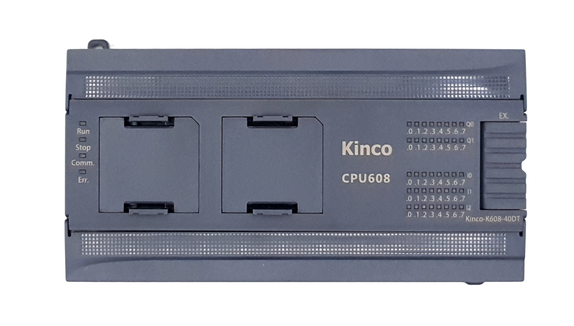
Your system has more sensors and actuators than a compact PLC with 24 channels can handle? The Kinco K608-40 comes with 24 digital inputs and 16 outputs, plus two BD slots for CAN, additional interfaces or I/O. Many machines manage without a single expansion module. 🏭 Typical applications Multi-station machines: assembly, test and packaging lines with many limit switches, light barriers and valves. Drives via CANopen: with the KB6-CAN board you control up to 64 CANopen nodes, or Kinco servo and stepper drives via the Kinco motion protocol. Positioning: the transistor variants output pulse and direction on four channels, three of them up to 200 kHz. Building services: pumps, ventilation and inverters via Modbus RTU, visualisation via Modbus TCP. ⚙️ Four variants K608-40DT: 24 V DC supply, 16 PNP transistor outputs K608-40AT: 100 – 240 V AC supply, 16 PNP transistor outputs K608-40DR: 24 V DC supply, 16 relay outputs K608-40AR: 100 – 240 V AC supply, 16 relay outputs 💡 The relay variants have no pulse outputs. For positioning tasks, choose DT or AT. ⚡ Inputs and outputs 24 digital inputs 24 V DC, wired as PNP or NPN, optically isolated, input delay below 40 µs (high-speed channels below 5 µs). PNP transistor outputs: 500 mA per channel at 24 V DC, protected against short circuit, inductive loads and reverse polarity. Relay outputs: 2 A per contact at 30 V DC or 250 V AC, max. 8 A per group of 4 channels, electrical life 100 000 operations at rated load. High-speed counters: 4 channels, HSC0 and HSC1 up to 200 kHz, HSC2 and HSC3 up to 20 kHz single-phase or 10 kHz A/B. 4 edge interrupts on I0.0 to I0.3. Pulse outputs (transistor variants only): 4 channels for PTO (pulse/direction) and PWM, PTO0 to PTO2 up to 200 kHz, PTO3 up to 10 kHz. Positioning instructions and a follow function are included in KincoBuilder. 🔌 Communication Ethernet 10/100 Mbit/s: Modbus TCP client and server, free communication via TCP and UDP, program upload/download and firmware update over the network. 2 × RS-485, galvanically isolated: 1200 to 115 200 bit/s, Modbus RTU master or slave, free protocol and programming on both ports. Up to 32 devices per port. 🧩 Expansion Two BD slots take expansion boards directly on the CPU. BD0 accepts communication and I/O boards (KB6-CAN, KB6-2COM, KB6-4DI, KB6-4DO), BD1 accepts I/O boards only (KB6-4DI, KB6-4DO). On top, up to 14 expansion modules connect to the local bus. The CPU supplies them with up to 1500 mA at 5 V and 360 mA at 24 V. From about 7 modules, or when the current budget runs out, you add the K680 power supply to the module row. 💻 Programming and memory You program the controller with KincoBuilder (IEC 61131-3) in ladder diagram (LD) or instruction list (IL), version V8.5.0.3 or later. The CPU offers 8k instructions of program memory and 20 kB of data memory (16 kB V area, 4 kB M area). 1000 standard instructions execute in 0.3 ms. On top come 256 timers, 256 counters, arrays with up to 1024 elements and a battery-backed real-time clock (deviation below 5 min per month at 25 °C). The V area and counter values are retained on power loss, and the battery is replaceable. 🔗 Compatible with Kinco K5 Terminal layout and power connection match the K5 series, existing K5 programs run without changes, and K5 expansion modules plug in directly. This lets you replace a K5 in the cabinet without rewiring or reprogramming. 🏷️ Manufacturer and standards Kinco Automation, based in Shanghai and Shenzhen, develops controllers, HMIs and drive technology for international machine builders. The K608-40 is CE marked (EN IEC 61000-6-2:2019, EN IEC 61000-6-4:2019) and tested to GB/T 15969.3-2007, which is equivalent to IEC 61131-2:2007. Protection class IP20, operation from −10 °C to +55 °C, 10 % – 95 % relative humidity without condensation, altitude up to 2000 m. 🔧 Mounting On 35 mm DIN rail or with M4 screws on the mounting plate. Dimensions 186 mm × 114 mm × 76 mm, the terminal blocks are pluggable.
Digital Outputs (Quantity & Type)
Nominal Supply Voltage
From €128.32 *

Preis exkl. MwSt., zzgl. Versandkosten

Kinco K6 PLC K608-40DR with 40 I/O
Your system has more sensors and actuators than a compact PLC with 24 channels can handle? The Kinco K608-40 comes with 24 digital inputs and 16 outputs, plus two BD slots for CAN, additional interfaces or I/O. Many machines manage without a single expansion module. 🏭 Typical applications Multi-station machines: assembly, test and packaging lines with many limit switches, light barriers and valves. Drives via CANopen: with the KB6-CAN board you control up to 64 CANopen nodes, or Kinco servo and stepper drives via the Kinco motion protocol. Positioning: the transistor variants output pulse and direction on four channels, three of them up to 200 kHz. Building services: pumps, ventilation and inverters via Modbus RTU, visualisation via Modbus TCP. ⚙️ Four variants K608-40DT: 24 V DC supply, 16 PNP transistor outputs K608-40AT: 100 – 240 V AC supply, 16 PNP transistor outputs K608-40DR: 24 V DC supply, 16 relay outputs K608-40AR: 100 – 240 V AC supply, 16 relay outputs 💡 The relay variants have no pulse outputs. For positioning tasks, choose DT or AT. ⚡ Inputs and outputs 24 digital inputs 24 V DC, wired as PNP or NPN, optically isolated, input delay below 40 µs (high-speed channels below 5 µs). PNP transistor outputs: 500 mA per channel at 24 V DC, protected against short circuit, inductive loads and reverse polarity. Relay outputs: 2 A per contact at 30 V DC or 250 V AC, max. 8 A per group of 4 channels, electrical life 100 000 operations at rated load. High-speed counters: 4 channels, HSC0 and HSC1 up to 200 kHz, HSC2 and HSC3 up to 20 kHz single-phase or 10 kHz A/B. 4 edge interrupts on I0.0 to I0.3. Pulse outputs (transistor variants only): 4 channels for PTO (pulse/direction) and PWM, PTO0 to PTO2 up to 200 kHz, PTO3 up to 10 kHz. Positioning instructions and a follow function are included in KincoBuilder. 🔌 Communication Ethernet 10/100 Mbit/s: Modbus TCP client and server, free communication via TCP and UDP, program upload/download and firmware update over the network. 2 × RS-485, galvanically isolated: 1200 to 115 200 bit/s, Modbus RTU master or slave, free protocol and programming on both ports. Up to 32 devices per port. 🧩 Expansion Two BD slots take expansion boards directly on the CPU. BD0 accepts communication and I/O boards (KB6-CAN, KB6-2COM, KB6-4DI, KB6-4DO), BD1 accepts I/O boards only (KB6-4DI, KB6-4DO). On top, up to 14 expansion modules connect to the local bus. The CPU supplies them with up to 1500 mA at 5 V and 360 mA at 24 V. From about 7 modules, or when the current budget runs out, you add the K680 power supply to the module row. 💻 Programming and memory You program the controller with KincoBuilder (IEC 61131-3) in ladder diagram (LD) or instruction list (IL), version V8.5.0.3 or later. The CPU offers 8k instructions of program memory and 20 kB of data memory (16 kB V area, 4 kB M area). 1000 standard instructions execute in 0.3 ms. On top come 256 timers, 256 counters, arrays with up to 1024 elements and a battery-backed real-time clock (deviation below 5 min per month at 25 °C). The V area and counter values are retained on power loss, and the battery is replaceable. 🔗 Compatible with Kinco K5 Terminal layout and power connection match the K5 series, existing K5 programs run without changes, and K5 expansion modules plug in directly. This lets you replace a K5 in the cabinet without rewiring or reprogramming. 🏷️ Manufacturer and standards Kinco Automation, based in Shanghai and Shenzhen, develops controllers, HMIs and drive technology for international machine builders. The K608-40 is CE marked (EN IEC 61000-6-2:2019, EN IEC 61000-6-4:2019) and tested to GB/T 15969.3-2007, which is equivalent to IEC 61131-2:2007. Protection class IP20, operation from −10 °C to +55 °C, 10 % – 95 % relative humidity without condensation, altitude up to 2000 m. 🔧 Mounting On 35 mm DIN rail or with M4 screws on the mounting plate. Dimensions 186 mm × 114 mm × 76 mm, the terminal blocks are pluggable.
Digital Outputs (Quantity & Type)
Nominal Supply Voltage
From €128.32 *

Preis exkl. MwSt., zzgl. Versandkosten

Kinco K6 PLC K608-40DR with 40 I/O
Your system has more sensors and actuators than a compact PLC with 24 channels can handle? The Kinco K608-40 comes with 24 digital inputs and 16 outputs, plus two BD slots for CAN, additional interfaces or I/O. Many machines manage without a single expansion module. 🏭 Typical applications Multi-station machines: assembly, test and packaging lines with many limit switches, light barriers and valves. Drives via CANopen: with the KB6-CAN board you control up to 64 CANopen nodes, or Kinco servo and stepper drives via the Kinco motion protocol. Positioning: the transistor variants output pulse and direction on four channels, three of them up to 200 kHz. Building services: pumps, ventilation and inverters via Modbus RTU, visualisation via Modbus TCP. ⚙️ Four variants K608-40DT: 24 V DC supply, 16 PNP transistor outputs K608-40AT: 100 – 240 V AC supply, 16 PNP transistor outputs K608-40DR: 24 V DC supply, 16 relay outputs K608-40AR: 100 – 240 V AC supply, 16 relay outputs 💡 The relay variants have no pulse outputs. For positioning tasks, choose DT or AT. ⚡ Inputs and outputs 24 digital inputs 24 V DC, wired as PNP or NPN, optically isolated, input delay below 40 µs (high-speed channels below 5 µs). PNP transistor outputs: 500 mA per channel at 24 V DC, protected against short circuit, inductive loads and reverse polarity. Relay outputs: 2 A per contact at 30 V DC or 250 V AC, max. 8 A per group of 4 channels, electrical life 100 000 operations at rated load. High-speed counters: 4 channels, HSC0 and HSC1 up to 200 kHz, HSC2 and HSC3 up to 20 kHz single-phase or 10 kHz A/B. 4 edge interrupts on I0.0 to I0.3. Pulse outputs (transistor variants only): 4 channels for PTO (pulse/direction) and PWM, PTO0 to PTO2 up to 200 kHz, PTO3 up to 10 kHz. Positioning instructions and a follow function are included in KincoBuilder. 🔌 Communication Ethernet 10/100 Mbit/s: Modbus TCP client and server, free communication via TCP and UDP, program upload/download and firmware update over the network. 2 × RS-485, galvanically isolated: 1200 to 115 200 bit/s, Modbus RTU master or slave, free protocol and programming on both ports. Up to 32 devices per port. 🧩 Expansion Two BD slots take expansion boards directly on the CPU. BD0 accepts communication and I/O boards (KB6-CAN, KB6-2COM, KB6-4DI, KB6-4DO), BD1 accepts I/O boards only (KB6-4DI, KB6-4DO). On top, up to 14 expansion modules connect to the local bus. The CPU supplies them with up to 1500 mA at 5 V and 360 mA at 24 V. From about 7 modules, or when the current budget runs out, you add the K680 power supply to the module row. 💻 Programming and memory You program the controller with KincoBuilder (IEC 61131-3) in ladder diagram (LD) or instruction list (IL), version V8.5.0.3 or later. The CPU offers 8k instructions of program memory and 20 kB of data memory (16 kB V area, 4 kB M area). 1000 standard instructions execute in 0.3 ms. On top come 256 timers, 256 counters, arrays with up to 1024 elements and a battery-backed real-time clock (deviation below 5 min per month at 25 °C). The V area and counter values are retained on power loss, and the battery is replaceable. 🔗 Compatible with Kinco K5 Terminal layout and power connection match the K5 series, existing K5 programs run without changes, and K5 expansion modules plug in directly. This lets you replace a K5 in the cabinet without rewiring or reprogramming. 🏷️ Manufacturer and standards Kinco Automation, based in Shanghai and Shenzhen, develops controllers, HMIs and drive technology for international machine builders. The K608-40 is CE marked (EN IEC 61000-6-2:2019, EN IEC 61000-6-4:2019) and tested to GB/T 15969.3-2007, which is equivalent to IEC 61131-2:2007. Protection class IP20, operation from −10 °C to +55 °C, 10 % – 95 % relative humidity without condensation, altitude up to 2000 m. 🔧 Mounting On 35 mm DIN rail or with M4 screws on the mounting plate. Dimensions 186 mm × 114 mm × 76 mm, the terminal blocks are pluggable.
Digital Outputs (Quantity & Type)
Nominal Supply Voltage
From €128.32 *

Preis exkl. MwSt., zzgl. Versandkosten

Kinco K6 PLC K606EA-30DT with 30 I/O
Your machine needs to measure pressures, temperatures or levels and drive an inverter via an analog signal, not just switch? The Kinco K606EA-30DT already has 4 analog inputs and 2 analog outputs on board. You save the first analog module and still keep all 14 expansion positions. 🏭 Typical applications Pressure and flow control: connect 4 – 20 mA transmitters directly, including 2-wire sensors, and calculate the control output in your program. Inverters with analog setpoint: an analog output with 0 – 10 V or 4 – 20 mA sets the speed, the digital outputs switch enable and direction. Heating, cooling, dosing: temperature and level monitoring with limit alarms without an extra analog module. Positioning tasks: 4 pulse outputs for stepper and servo drives, three of them up to 200 kHz. ⚡ Inputs and outputs 14 digital inputs 24 V DC, wired as PNP or NPN, optically isolated, input delay below 40 µs (high-speed channels below 5 µs). 10 PNP transistor outputs: 500 mA per channel at 24 V DC, protected against short circuit, inductive loads and reverse polarity. 4 analog inputs: 4 – 20 mA, 0 – 20 mA, 1 – 5 V and 0 – 10 V, 12-bit resolution, accuracy 0.3 % of full scale, about 30 conversions per second and channel. A red LED indicates an out-of-range value. 2 analog outputs: 4 – 20 mA, 0 – 20 mA, 1 – 5 V and 0 – 10 V, 12 bit, accuracy 0.3 % of full scale, load up to 500 Ω in current mode, at least 1 kΩ in voltage mode. High-speed counters: 4 channels, HSC0 and HSC1 up to 200 kHz, HSC2 and HSC3 up to 20 kHz single-phase or 10 kHz A/B. 4 edge interrupts on I0.0 to I0.3. Pulse outputs: 4 channels for PTO (pulse/direction) and PWM, PTO0 to PTO2 up to 200 kHz, PTO3 up to 10 kHz. 24 V DC supply; the device provides 300 mA at 24 V for sensors. 🔌 Communication Ethernet 10/100 Mbit/s: Modbus TCP client and server, free communication via TCP and UDP, program upload/download and firmware update over the network. 2 × RS-485, galvanically isolated: 1200 to 115 200 bit/s, Modbus RTU master or slave, free protocol and programming on both ports. Up to 32 devices per port. 🧩 Expansion Two BD slots take expansion boards directly on the CPU. BD0 accepts communication and I/O boards (KB6-CAN, KB6-2COM, KB6-4DI, KB6-4DO), BD1 accepts I/O boards only (KB6-4DI, KB6-4DO). On top, up to 14 expansion modules connect to the local bus. The CPU supplies them with up to 1500 mA at 5 V and 360 mA at 24 V. From about 7 modules, or when the current budget runs out, you add the K680 power supply to the module row. 💻 Programming and memory You program the controller with KincoBuilder (IEC 61131-3) in ladder diagram (LD) or instruction list (IL), version V8.5.0.3 or later. The CPU offers 8k instructions of program memory and 20 kB of data memory (16 kB V area, 4 kB M area). 1000 standard instructions execute in 0.3 ms. On top come 256 timers, 256 counters, arrays with up to 1024 elements and a battery-backed real-time clock (deviation below 5 min per month at 25 °C). The V area and counter values are retained on power loss, and the battery is replaceable. 🔗 Compatible with Kinco K5 Terminal layout and power connection match the K5 series, existing K5 programs run without changes, and K5 expansion modules plug in directly. This lets you replace a K5 in the cabinet without rewiring or reprogramming. 🏷️ Manufacturer and standards Kinco Automation, based in Shanghai and Shenzhen, develops controllers, HMIs and drive technology for international machine builders. The K606EA-30DT is CE marked (EN IEC 61000-6-2:2019, EN IEC 61000-6-4:2019) and tested to GB/T 15969.3-2007, which is equivalent to IEC 61131-2:2007. Protection class IP20, operation from −10 °C to +55 °C, 10 % – 95 % relative humidity without condensation, altitude up to 2000 m. 🔧 Mounting On 35 mm DIN rail or with M4 screws on the mounting plate. Dimensions 186 mm × 114 mm × 76 mm, the terminal blocks are pluggable.
€192.00 *

Preis exkl. MwSt., zzgl. Versandkosten

Compatible software

Kinco Builder - Programming software for Kinco PLCs of the MK, KS, K2, K6 and K6S series
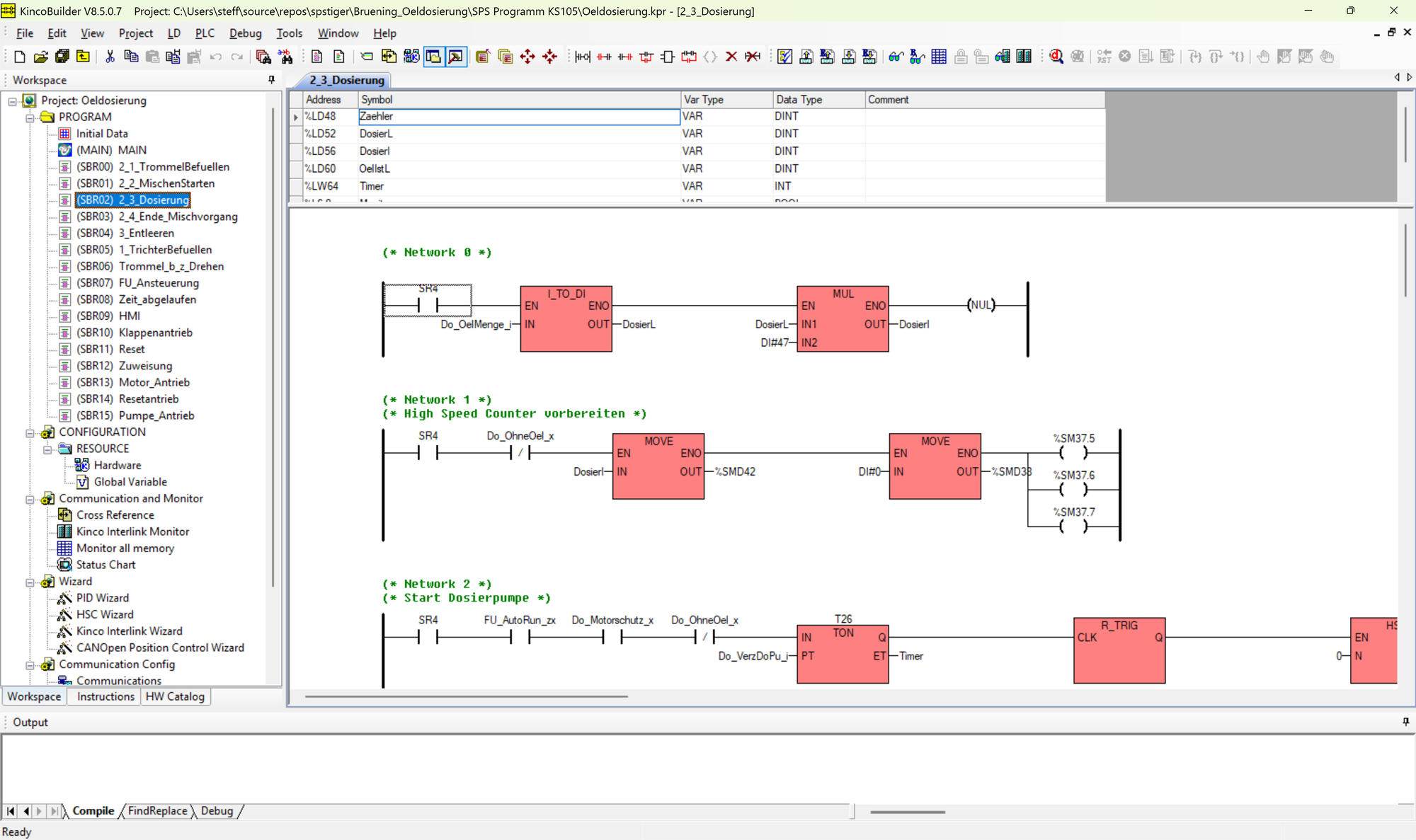
Kinco Builder is the Kinco programming software for the MK (combined HMI and PLC), KS, K2, K6 and K6S series controllers.The software is small and lightweight, free of charge and offers a wide range of instructions and functions for PLCs:Bit instructionsMathematical calculations including circular functions (sine etc.) and logarithmsType conversions e.g. real to integerProgram structures (For / Next)Own functions (no function blocks with their own memory instance)InterruptsCommunication functions such as free serial communication with ASCII or Modbus RTU Counters and timersClock functionsPIDPosition functions for steppers and others (PWM, PTO etc.)Kinco Builder uses Ladder Diagram (LD) and Instruction List (IL).
€0.00 *

Preis exkl. MwSt., zzgl. Versandkosten

Accessories

Kinco KB6-CAN communication extension for K6 PLC
You want to connect servo drives, stepper drivers or CANopen I/O to your K6 without adding a gateway to the cabinet? The KB6-CAN adds a CAN interface to the CPU. It plugs into BD slot BD0. 🌐 Functions CANopen master: up to 64 slaves with 8 TPDO and 8 RPDO each, error monitoring via node guarding and heartbeat. Kinco motion protocol: simple positioning instructions for up to 16 Kinco servo and stepper drives on the CAN bus. Free CAN communication for your own telegrams. Baud rates: 10, 20, 50, 125, 500 and 800 kbit/s as well as 1 Mbit/s. Connection: RJ45 (pin 1 CAN_H, pin 2 CAN_L, pin 3 CAN_GND), built-in termination resistor switchable via DIP switch. 💡 On the K606EA and K608, only BD0 accepts communication boards; BD1 is reserved for I/O boards. 🔧 Mounting and environment The board plugs directly onto the CPU, needs no space on the DIN rail and no separate supply. A LINK LED indicates that it is seated correctly.
€38.00 *

Preis exkl. MwSt., zzgl. Versandkosten

Communication extension RS-232/485 Kinco KB6-2COM for K6 PLC
Two serial ports are not enough because an inverter, a barcode scanner and a scale all need to be connected? The KB6-2COM adds an RS-232 (port 0) and another RS-485 (port 3) to the K6. It plugs into BD slot BD0. 🔌 Interfaces RS-232 (port 0): Modbus RTU slave, free protocol and programming, for example for scanners, printers or an older panel. RS-485 (port 3): Modbus RTU master or slave and programming. Baud rate: 1200 to 115 200 bit/s. Connection: shared DB9 connector. RS-232 on pins 2 (RxD), 3 (TxD) and 5 (GND), RS-485 on pins 1 (B) and 6 (A). 💡 On the K606EA and K608, only BD0 accepts communication boards. 🔧 Mounting and environment The board plugs directly onto the CPU, needs no space on the DIN rail and no separate supply. A LINK LED indicates that it is seated correctly.
€20.00 *

Preis exkl. MwSt., zzgl. Versandkosten

Digital input extension Kinco KB6-4DI for K6 PLC
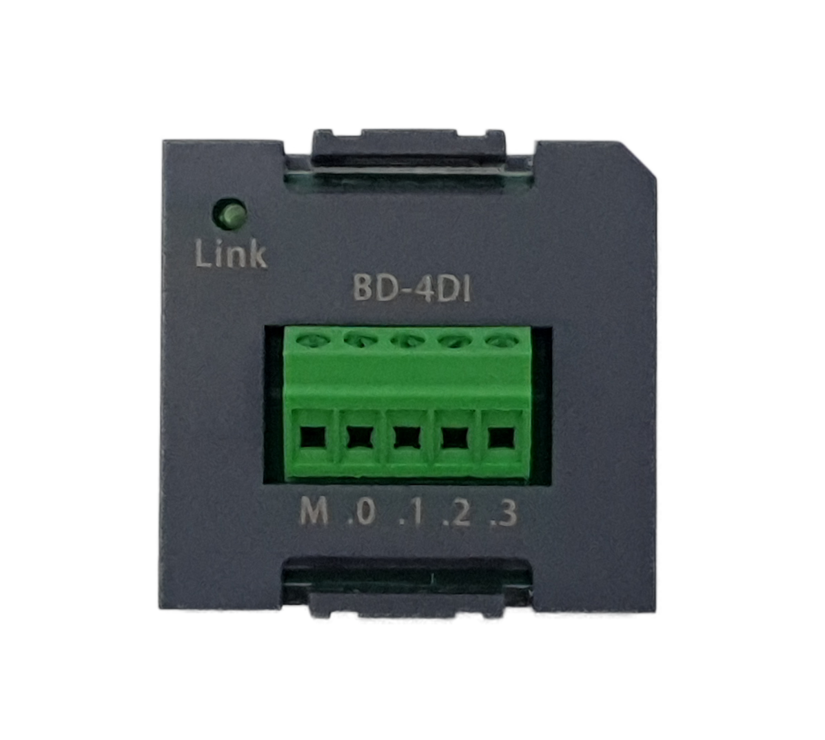
You only need a few more inputs and a whole expansion module would be overkill? The KB6-4DI plugs directly onto the K6 CPU and adds four digital inputs. It fits any BD slot, so on the K606EA and K608 also BD1. ⚡ Inputs 4 digital inputs 24 V DC, wired as PNP or NPN. Input current 3.5 mA at 24 V DC, input delay below 40 µs. Optocoupler isolation with 500 V AC. Connection via terminal block with 3.81 mm pitch. 🔧 Mounting and environment The board plugs directly onto the CPU, needs no space on the DIN rail and no separate supply. A LINK LED indicates that it is seated correctly.
€20.00 *

Preis exkl. MwSt., zzgl. Versandkosten

Digital output extension Kinco KB6-4DO for K6 PLC
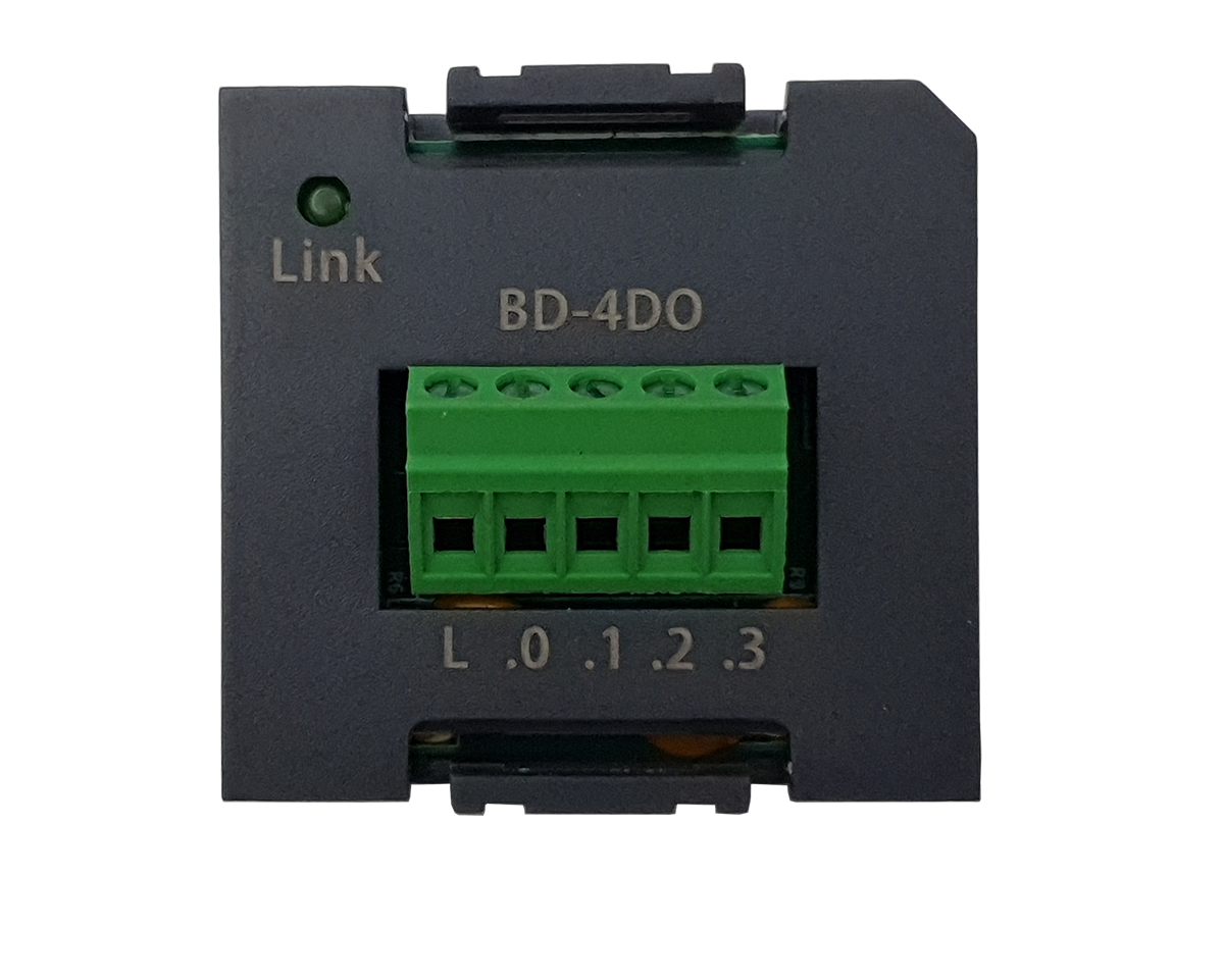
Two signal lamps and a valve don't justify a whole output module? The KB6-4DO plugs directly onto the K6 CPU and adds four outputs. It fits any BD slot, so on the K606EA and K608 also BD1. ⚡ Outputs 4 opto-relay outputs 24 V DC (permissible 20.4 V to 28.8 V DC), wired as PNP or NPN via the common terminal L. Output current 300 mA rated, max. 500 mA per channel, short-circuit proof and protected against switch-off peaks of inductive loads. Switching delay below 10 ms. For fast pulses, use the CPU's transistor outputs. Optocoupler isolation with 500 V AC. Connection via terminal block with 3.81 mm pitch. 🔧 Mounting and environment The board plugs directly onto the CPU, needs no space on the DIN rail and no separate supply. A LINK LED indicates that it is seated correctly.
€24.00 *

Preis exkl. MwSt., zzgl. Versandkosten

Spannungsversorgung Kinco K680 für Erweiterungen für K6 SPS
Your K6 has more expansion modules than its own bus supply can carry? The K680 (also PS680) feeds fresh 5 V and 24 V into the expansion bus. All modules after the K680 are powered by it, all modules before it by the CPU. ⚡ Technical data Input: 85 to 265 V AC. Output to the bus: up to 1000 mA at 5 V (logic supply) and up to 250 mA at 24 V (relay drive). Plug & play: uses no CPU memory and does not need to be configured in KincoBuilder. Status indication: PW LED. 💡 How to plan the current budget The K6 CPU provides 1500 mA at 5 V and 360 mA at 24 V. Add up the bus consumption of your modules, for example 210 mA for a K621-16DX, or 210 mA and 120 mA for a K622-16XR. When the budget gets tight, you place the K680 at the right position in the module row. Kinco generally recommends it from 7 expansion modules. Make sure the K680 and the CPU are fed from the same supply. 🔧 Mounting and environment Protection class IP20, operation from −10 °C to +55 °C, CE marked. Mounting on 35 mm DIN rail or with M4 screws, connection via screw terminals. Dimensions 75 mm × 114 mm × 70 mm (W × H × D).
From €25.60 *

Preis exkl. MwSt., zzgl. Versandkosten

Digitalerweiterung Kinco K521-16DX für K6 SPS
Limit switches, light barriers and push buttons have used up your CPU inputs? The K521-16DX expands your Kinco controller with 16 digital inputs. ⚡ Technical data 16 digital inputs in 2 groups of 8 channels, 24 V DC, wired as PNP or NPN, 3.5 mA input current, optically isolated. Input delay below 40 µs. Status indication via green LED per channel. Power comes via the expansion bus: the module draws up to 210 mA at 5 V. A K6 CPU provides a total of 1500 mA at 5 V and 360 mA at 24 V. If the budget is not enough for your module row, you insert the K680 power supply. 💡 Expansion module of the Kinco K5 series. It works with K5 CPUs and directly with all K6 CPUs (K606, K606EA, K608), whose expansion bus is compatible with the K5. Technically it corresponds to the K6 module K621-16DX. 🔧 Mounting and environment Protection class IP20, operation from −10 °C to +55 °C, CE marked. Mounting on 35 mm DIN rail or with M4 screws, connection via screw terminals.
€62.40 *

Preis exkl. MwSt., zzgl. Versandkosten

Digitalerweiterung Kinco K522-16DT für K6 SPS
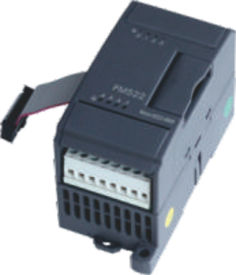
Valve terminals, signal lamps and auxiliary contactors need more outputs than your CPU has? The K522-16DT expands your Kinco controller with 16 transistor outputs. ⚡ Technical data 16 transistor outputs in 4 groups of 4 channels, PNP, 500 mA per channel at 24 V DC, protected against short circuit, inductive loads and reverse polarity. Output delay below 25 µs. Status indication via green LED per channel. Power comes via the expansion bus: the module draws up to 240 mA at 5 V. A K6 CPU provides a total of 1500 mA at 5 V and 360 mA at 24 V. If the budget is not enough for your module row, you insert the K680 power supply. 💡 Expansion module of the Kinco K5 series. It works with K5 CPUs and directly with all K6 CPUs (K606, K606EA, K608), whose expansion bus is compatible with the K5. Technically it corresponds to the K6 module K622-16DT. 🔧 Mounting and environment Protection class IP20, operation from −10 °C to +55 °C, CE marked. Mounting on 35 mm DIN rail or with M4 screws, connection via screw terminals.
€83.30 *

Preis exkl. MwSt., zzgl. Versandkosten

Digitalerweiterung Kinco K523-16DT für K6 SPS
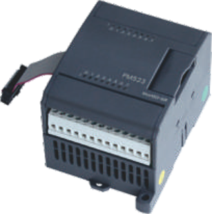
You want to connect a machine station with sensors and valves in one go? The K523-16DT adds 8 inputs and 8 transistor outputs to your Kinco controller. ⚡ Technical data 8 digital inputs 24 V DC, wired as PNP or NPN, 3.5 mA input current, optically isolated. 8 transistor outputs in 2 groups of 4 channels, PNP, 500 mA per channel at 24 V DC, protected against short circuit, inductive loads and reverse polarity. Status indication via green LED per channel. Power comes via the expansion bus: the module draws up to None mA at 5 V. A K6 CPU provides a total of 1500 mA at 5 V and 360 mA at 24 V. If the budget is not enough for your module row, you insert the K680 power supply. 💡 Expansion module of the Kinco K5 series. It works with K5 CPUs and directly with all K6 CPUs (K606, K606EA, K608), whose expansion bus is compatible with the K5. Technically it corresponds to the K6 module K623-16DT. 🔧 Mounting and environment Protection class IP20, operation from −10 °C to +55 °C, CE marked. Mounting on 35 mm DIN rail or with M4 screws, connection via screw terminals.
€77.00 *

Preis exkl. MwSt., zzgl. Versandkosten

Mixed digital expansion Kinco PM523-08DT for K6 PLC
You are missing a few inputs and outputs, for example for an additional cylinder with end position sensors? The slim K623-08DT adds 4 inputs and 4 transistor outputs to your Kinco K6. ⚡ Technical data 4 digital inputs 24 V DC, wired as PNP or NPN, 3.5 mA input current, optically isolated. 4 transistor outputs PNP, 500 mA per channel at 24 V DC, protected against short circuit, inductive loads and reverse polarity. Output delay below 25 µs. Status indication via green LED per channel. Power comes via the expansion bus: the module draws up to 200 mA at 5 V. A K6 CPU provides a total of 1500 mA at 5 V and 360 mA at 24 V. If the budget is not enough for your module row, you insert the K680 power supply. 🔧 Mounting and environment Protection class IP20, operation from −10 °C to +55 °C, CE marked. Mounting on 35 mm DIN rail or with M4 screws, connection via screw terminals. Dimensions 50 mm × 114 mm × 70 mm (W × H × D).
€60.40 *

Preis exkl. MwSt., zzgl. Versandkosten

Digitalerweiterung (Relais) Kinco K623-16DR für K6 SPS
You need more inputs for sensors and potential-free contacts for 230 V loads at the same time? The K623-16DR adds 8 inputs and 8 relay outputs to your Kinco K6 in one module. ⚡ Technical data 8 digital inputs 24 V DC, wired as PNP or NPN, 3.5 mA input current, optically isolated. 8 relay outputs in 2 groups of 4 channels. Switching capacity: 2 A per contact at 30 V DC or 250 V AC, max. 8 A per group of 4 channels. Electrical life 100 000 operations at rated load, coil/contact isolation 2000 V. Status indication via green LED per channel. Power comes via the expansion bus: the module draws up to 210 mA at 5 V and 60 mA at 24 V. A K6 CPU provides a total of 1500 mA at 5 V and 360 mA at 24 V. If the budget is not enough for your module row, you insert the K680 power supply. 🔧 Mounting and environment Protection class IP20, operation from −10 °C to +55 °C, CE marked. Mounting on 35 mm DIN rail or with M4 screws, connection via screw terminals. Dimensions 75 mm × 114 mm × 70 mm (W × H × D).
€77.00 *

Preis exkl. MwSt., zzgl. Versandkosten

Digitalausgangserweiterung Relais Kinco K622-16XR für K6 SPS
You need to switch contactors, solenoid valves or 230 V AC loads and the CPU outputs are not enough? The K622-16XR expands your Kinco K6 with 16 potential-free relay outputs. ⚡ Technical data 16 relay outputs in 4 groups of 4 channels. Switching capacity: 2 A per contact at 30 V DC or 250 V AC, max. 8 A per group of 4 channels. Electrical life 100 000 operations at rated load, coil/contact isolation 2000 V. Switching times: turn-on max. 10 ms, turn-off max. 5 ms. Status indication via green LED per channel. Power comes via the expansion bus: the module draws up to 210 mA at 5 V and 120 mA at 24 V. A K6 CPU provides a total of 1500 mA at 5 V and 360 mA at 24 V. If the budget is not enough for your module row, you insert the K680 power supply. 🔧 Mounting and environment Protection class IP20, operation from −10 °C to +55 °C, CE marked. Mounting on 35 mm DIN rail or with M4 screws, connection via screw terminals. Dimensions 75 mm × 114 mm × 70 mm (W × H × D).
€82.00 *

Preis exkl. MwSt., zzgl. Versandkosten

Analog expansion Kinco K531-04IV for K6 PLC
Pressure, level, flow: your transmitters deliver standard signals and the CPU has no or too few analog inputs? The K531-04IV takes four current or voltage signals. ⚡ Technical data 4 analog inputs for 4 – 20 mA, 0 – 20 mA, 1 – 5 V and 0 – 10 V, selectable per channel. Resolution 12 bit, accuracy 0.3 % of full scale, about 15 conversions per second and channel. Input limits 24 mA or 12 V, input resistance up to 500 Ω in current mode, above 4 MΩ in voltage mode. Diagnostics: red LED and error message to the CPU when out of range. External supply 24 V DC, at least 100 mA. Power comes via the expansion bus: the module draws up to 172 mA at 5 V. A K6 CPU provides a total of 1500 mA at 5 V and 360 mA at 24 V. If the budget is not enough for your module row, you insert the K680 power supply. 💡 Expansion module of the Kinco K5 series. It works with K5 CPUs and directly with all K6 CPUs (K606, K606EA, K608), whose expansion bus is compatible with the K5. Technically it corresponds to the K6 module K631-04IV. 🔧 Mounting and environment Protection class IP20, operation from −10 °C to +55 °C, CE marked. Mounting on 35 mm DIN rail or with M4 screws, connection via screw terminals.
€102.00 *

Preis exkl. MwSt., zzgl. Versandkosten

Analog expansion Kinco K533-04IV for K6 PLC
You want to close a control loop: actual value in from the transmitter, manipulated value out to a valve or inverter? The K533-04IV provides 2 analog inputs and 2 analog outputs in one module. ⚡ Technical data 2 analog inputs for 4 – 20 mA, 0 – 20 mA, 1 – 5 V and 0 – 10 V, 12 bit, accuracy 0.3 % of full scale. 2 analog outputs for 4 – 20 mA, 0 – 20 mA, 1 – 5 V and 0 – 10 V, 12 bit, accuracy 0.3 % of full scale, load up to 500 Ω in current mode, above 1 kΩ in voltage mode. Conversion rate about 15 per second and channel. Diagnostics: red LED when the rated range is exceeded. External supply 24 V DC, at least 100 mA. Power comes via the expansion bus: the module draws up to 166 mA at 5 V. A K6 CPU provides a total of 1500 mA at 5 V and 360 mA at 24 V. If the budget is not enough for your module row, you insert the K680 power supply. 💡 Expansion module of the Kinco K5 series. It works with K5 CPUs and directly with all K6 CPUs (K606, K606EA, K608), whose expansion bus is compatible with the K5. Technically it corresponds to the K6 module K633-04IV. 🔧 Mounting and environment Protection class IP20, operation from −10 °C to +55 °C, CE marked. Mounting on 35 mm DIN rail or with M4 screws, connection via screw terminals.
€121.00 *

Preis exkl. MwSt., zzgl. Versandkosten

Temperaturerweiterung (PT100) Kinco K531-04RD für K6 SPS
You want to measure temperatures in an oven, cooling circuit or barn directly with resistance thermometers, without transmitters in between? The K531-04RD reads four Pt100, Pt1000 or Cu50 sensors directly. ⚡ Technical data 4 measuring channels for Pt100 (−200 °C to +850 °C), Pt1000 (−50 °C to +300 °C) and Cu50 (−50 °C to +150 °C) as well as direct resistance (0 Ω to 2000 Ω). Connection in 2-wire or 3-wire technology. Accuracy ±0.5 °C or ±1 Ω, resolution 24 bit, about one conversion per second and channel. Diagnostics: red LED and error message to the CPU when out of range. External supply 24 V DC, at least 100 mA. Power comes via the expansion bus: the module draws up to 172 mA at 5 V. A K6 CPU provides a total of 1500 mA at 5 V and 360 mA at 24 V. If the budget is not enough for your module row, you insert the K680 power supply. 💡 Expansion module of the Kinco K5 series. It works with K5 CPUs and directly with all K6 CPUs (K606, K606EA, K608), whose expansion bus is compatible with the K5. Technically it corresponds to the K6 module K631-04RD. 🔧 Mounting and environment Protection class IP20, operation from −10 °C to +55 °C, CE marked. Mounting on 35 mm DIN rail or with M4 screws, connection via screw terminals.
€114.00 *

Preis exkl. MwSt., zzgl. Versandkosten

Thermoelement-Erweiterung Kinco K531-04TC für K6 SPS
Furnaces, extruders, hot runners: where resistance thermometers reach their limits, thermocouples keep measuring. The K531-04TC reads four thermocouples directly. ⚡ Technical data 4 measuring channels for thermocouples type J (−210 °C to +1200 °C), K (−270 °C to +1300 °C), E (−270 °C to +1000 °C) and S (−50 °C to +1600 °C). Cold junction compensation internal or external, selectable. Accuracy 0.1 % of full scale, resolution 24 bit, about one conversion per second and channel. Diagnostics: red LED and error message to the CPU when out of range. External supply 24 V DC, at least 100 mA. Power comes via the expansion bus: the module draws up to 172 mA at 5 V. A K6 CPU provides a total of 1500 mA at 5 V and 360 mA at 24 V. If the budget is not enough for your module row, you insert the K680 power supply. 💡 Expansion module of the Kinco K5 series. It works with K5 CPUs and directly with all K6 CPUs (K606, K606EA, K608), whose expansion bus is compatible with the K5. Technically it corresponds to the K6 module K631-04TC. 🔧 Mounting and environment Protection class IP20, operation from −10 °C to +55 °C, CE marked. Mounting on 35 mm DIN rail or with M4 screws, connection via screw terminals.
€114.00 *

Preis exkl. MwSt., zzgl. Versandkosten