


Frequency inverter · Quick Start Guide
Kinco KC100 – First-Time Setup
Step-by-step instructions for the safe initial commissioning of a Kinco KC100 frequency inverter with an asynchronous motor — from motor parameters and the setpoint source to Modbus operation.
The KC100 supports asynchronous motors only. Take the following parameters directly from the motor nameplate. Only then start auto-tuning — otherwise the vector control runs with default values and loses torque and speed quality.
| Parameter | Name | Value to set | Description |
|---|---|---|---|
| F03.02 | Rated motor power | Nameplate kW | e.g. 1.5 kW · range 0.1–15.0 kW |
| F03.03 | Rated motor voltage | Nameplate V | e.g. 230 V (single-phase) or 400 V (three-phase) |
| F03.04 | Rated motor current | Nameplate A | range 0.01–100.00 A |
| F03.05 | Rated motor frequency | 50.00 Hz | Typically 50 Hz in Europe |
| F03.06 | Rated motor speed | Nameplate rpm | e.g. 1430 rpm (4-pole motor) · range 1–65535 rpm |
| F03.09 | Motor parameters auto-tuning | 1 | 1 = Static auto-tuning (motor stays still, recommended) · 2 = Rotating auto-tuning (motor must rotate freely) |
1 or
2, then press RUN on the keypad. The drive runs the
measurement and writes the results automatically into F03.10–F03.14 (stator resistance,
rotor resistance, leakage inductance, mutual inductance, no-load current). Only after
auto-tuning does the vector mode reach its full torque quality.
The KC100 has no "motor type" parameter (no F03.00). The series supports asynchronous motors only — the motor group starts directly with F03.02. Synchronous motors (PMSM) and a second motor parameter set are reserved for the KC200.
Defines where the inverter receives the start/stop command from. Only sets the start/stop command — the frequency setpoint is configured separately in F01.04 (see step 3).
Factory default. Ideal for first tests and manual operation.
For external pushbutton operation (typical DI assignment, see step 5).
Control by a PLC or HMI over RS-485 (details in step 6).
Defines the source of the frequency setpoint. Selectable independently from the control source in F01.03.
Factory default. F01.10 = 50.00 Hz default.
Scaling via the F09 group (min/max voltage, min/max frequency).
Convenient for local tests without external hardware.
A written value of 0–60000 corresponds to 0.00–600.00 Hz (resolution 0.01 Hz).
DI4 is the only pulse-capable input on the KC100.
Configuration in group F16.
Up to 8 steps via 3 DI inputs with function 21–23 (see step 5).
F01.11 = max. frequency (default 50 Hz, max. 600 Hz),
F01.13 = upper limit, F01.14 = lower limit.
F01.10 holds the digital setpoint in keypad operation.
Ramp times refer to the maximum frequency (F01.11) by default. With 50 Hz and an acceleration time of 10 s, the drive accelerates from 0 to 50 Hz in 10 s.
| Parameter | Name | Value to set | Description |
|---|---|---|---|
| F01.21 | Ramp reference value | 0 | 0 = max. frequency F01.11 · 1 = setpoint frequency |
| F01.22 | Time unit | 1 | 0 = 1 s · 1 = 0.1 s (factory default) |
| F01.23 | Acceleration time 1 | 10.0 s | range 0.0–6000.0 s · factory default 10.0 s |
| F01.24 | Deceleration time 1 | 10.0 s | range 0.0–6000.0 s · factory default same as F01.23 |
| F01.20 | Ramp shape | 0 | 0 = linear · 1 = S-curve (for jerk-free start) |
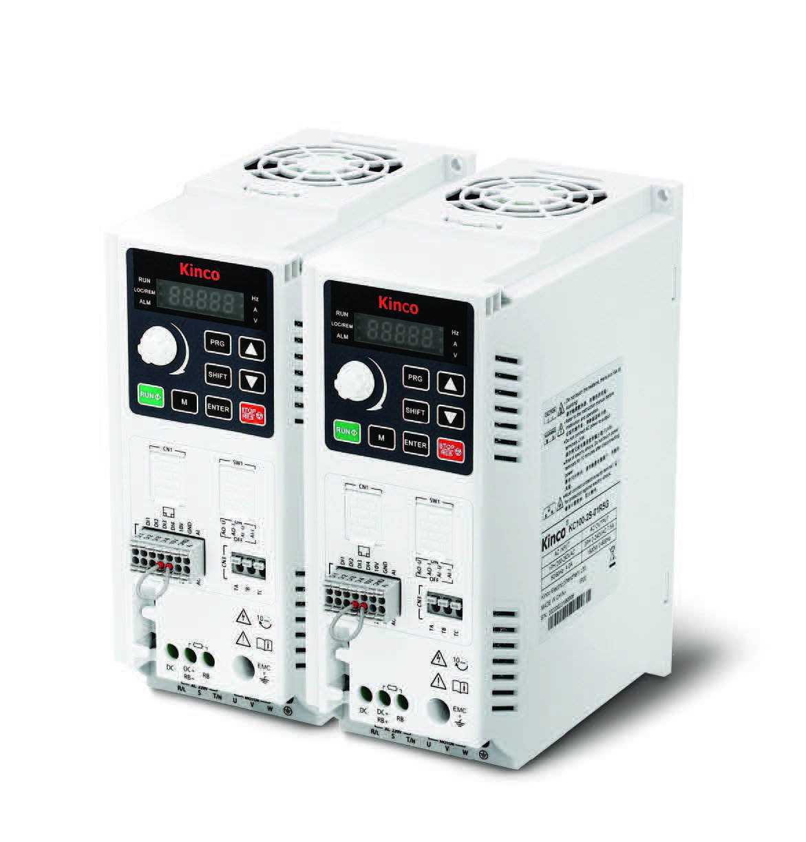
The KC100 has 4 digital inputs (DI1–DI4), one analog input, one analog output and one relay. DI4 is also pulse-capable (high-frequency pulse). Only relevant if F01.03 = 1 (terminal I/O) was selected.
| Terminal | Function | Note |
|---|---|---|
| DI1 | Forward run (FWD) — factory default | F08.00 = 1 |
| DI2 | Reverse run (REV) — factory default | F08.01 = 2 |
| DI3 | Freely assignable | F08.02 = 0 (factory default: no function) |
| DI4 | Freely assignable · also high-frequency pulse input | F08.03 = 0 · for PULSE setpoint set F08.03 = 47 |
| COM | Common ground for DI1–DI4 | Reference potential for the digital inputs |
| AI | Analog input 0–10 V or 0/4–20 mA | Check jumper position on the control board (V/I) |
| AO | Analog output 0–10 V or 0/4–20 mA | Check jumper position on the control board (V/I) |
| TA-TB-TC | Relay output (changeover contact) | Default: "drive fault" — function configurable via F10.02 |
| Value | Function | Value | Function |
|---|---|---|---|
| 1 | Forward run (FWD) | 16 | Fault reset |
| 2 | Reverse run (REV) | 21–23 | Multi-reference terminal 1–3 |
| 3 | 3-wire control | 25/26 | Terminal UP / DOWN |
| 4 / 5 | Forward jog / Reverse jog | 32/33 | Acc/Dec time selection 1 / 2 |
| 6 | Coast stop | 43 | Counter input (DI4) |
| 7 | Emergency stop | 47 | High-frequency pulse input (DI4) |
F08.14 defines per DI whether closing
(default) or opening is active. F08.30–F08.33 set individual filter
times per DI (default 10 ms).
The KC100 has only Modbus RTU as a communication interface — no CAN, no Ethernet. The values below must match the master (PLC, HMI, gateway).
| Parameter | Name | Value to set | Description |
|---|---|---|---|
| F14.01 | Baud rate | 5 | 0=1200 · 1=2400 · 2=4800 · 3=9600 · 4=19200 · 5=38400 (factory default) · 6=57600 · 7=115200 |
| F14.02 | Data format | 0 | 0=N,8,1 (factory default) · 1=E,8,1 · 2=O,8,1 · 3=N,8,2 · 4=E,8,2 · 5=O,8,2 |
| F14.03 | Slave address | 1 | range 1–247 (0 = broadcast, not addressable) |
| F14.04 | Response delay | 2 ms | range 0–20 ms |
| F14.05 | Communication timeout | 0.0 s | 0.0 = disabled · otherwise range 0.1–60.0 s |
Prerequisite: F01.03 = 2 (control source: communication) and/or
F01.04 = 5 (frequency source: communication). Write via Function Code 06
(Single Write) or 16 (Multiple Write).
| Name | Hex address | Dec. address | Value (hex) | Value (dec) | Meaning |
|---|---|---|---|---|---|
| Control command (control word) | 0x7000 | 28672 | 0x0001 | 1 | Start forward run (FWD) |
| Control command | 0x7000 | 28672 | 0x0002 | 2 | Start reverse run (REV) |
| Control command | 0x7000 | 28672 | 0x0005 | 5 | Ramp stop (controlled) |
| Control command | 0x7000 | 28672 | 0x0006 | 6 | Emergency stop |
| Control command | 0x7000 | 28672 | 0x0007 | 7 | Coast stop (free run) |
| Control command | 0x7000 | 28672 | 0x0008 | 8 | Fault reset |
| Frequency setpoint | 0x7010 | 28688 | 0x1388 | 5000 | Example: 50.00 Hz · resolution 0.01 Hz · range 0–60000 |
The KC100 has a built-in brake chopper in all power classes. For applications with frequent or fast braking, connect an external braking resistor to terminals RB+ and RB−.
| Parameter | Name | Value to set | Description |
|---|---|---|---|
| F13.17 | Brake chopper threshold voltage | 700 V | 400 V drives: 700 V (default) · 230 V drives: 360 V · 440 V drives: 750 V · range 200.0–820.0 V |
| F13.18 | Brake chopper duty cycle | 100.0 % | duty ratio · default 100 % · reduce to 50–80 % for small resistors |
No braking resistor is included — only the chopper. Size resistance and power rating by application (rule of thumb: 100 Ω · 200 W for 0.4–0.75 kW; 75 Ω · 300 W for 1.5 kW; 50 Ω · 500 W for 2.2 kW; oversize for continuous braking duty). Undersized resistors may be destroyed thermally.
E0001 = overcurrent during acceleration (extend ramp, check load),
E0003 = overvoltage during braking (extend ramp or connect a braking
resistor), E0010 = motor ground short circuit,
E0024 = motor overload. Acknowledge with the STOP/RESET key or by
writing 0x0008 to 0x7000.

Available in 30 days, delivery time 3 bis 5 Tage
Preis exkl. MwSt., zzgl. Versandkosten