



Kinco iSMK – Support, Wiring Diagram & Commissioning
Everything for your Kinco iSMK after purchase – for all six versions with 200, 400 and 750 W, 24–60 V DC, RS-485 and CANopen, with and without holding brake:
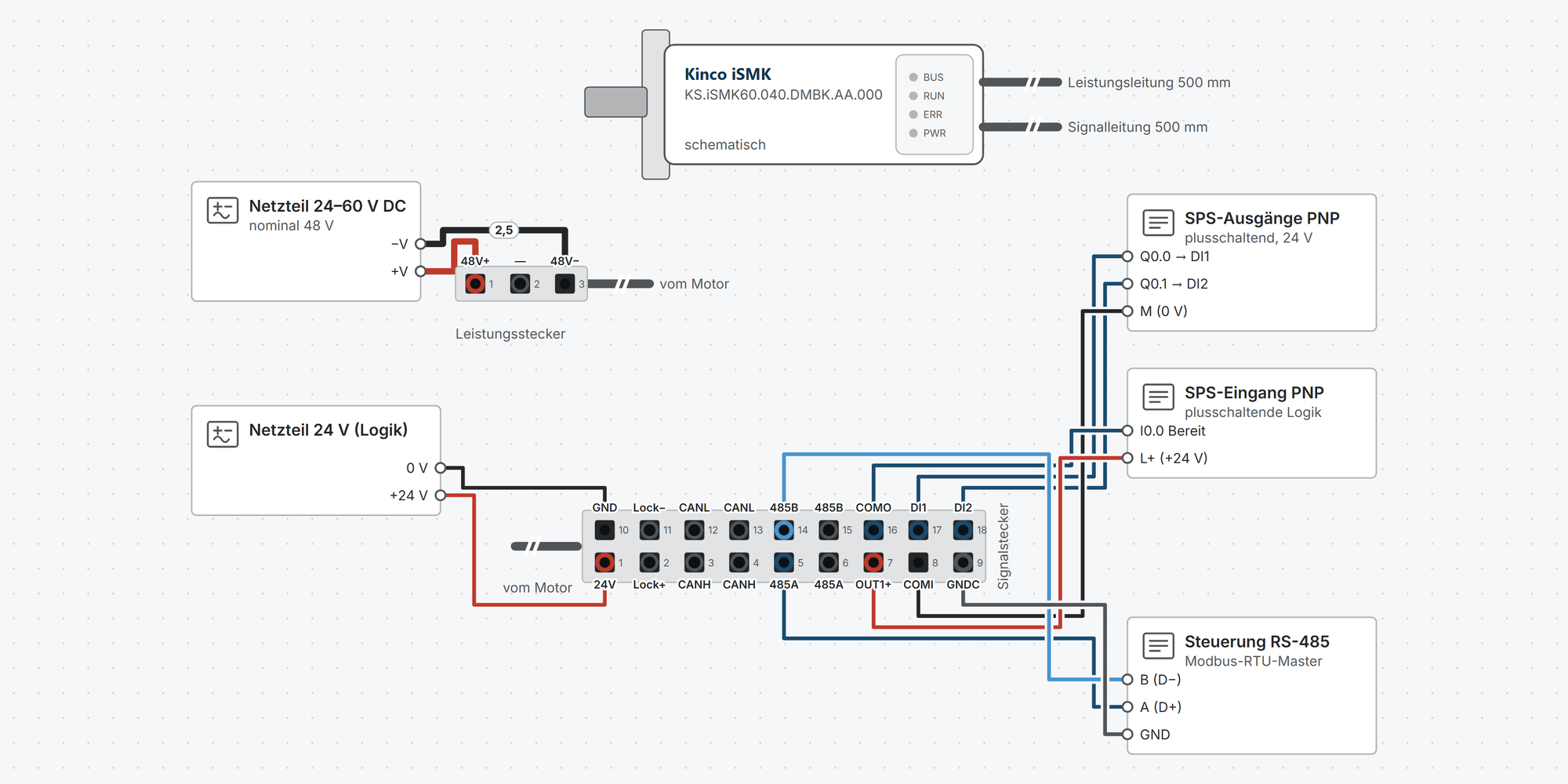
Interactive wiring diagram: power and logic supply, emergency brake release, digital inputs PNP and NPN, digital output, Kinco Servo Pro, Modbus RTU and CANopen, plus pin layout, mating connector and wire colours of both connectors, with cable cross-sections and parameters
First steps: commissioning in ten steps, from wiring to the first motion with Kinco Servo Pro
Downloads: user manual, dimension drawings and 3D models
Free support from spstiger if you get stuck
Interactive wiring diagram
Tap a terminal or wire in the drawing to see details.
Terminal overview iSMK
| Terminal | Group | mm² | Function |
|---|---|---|---|
| 48V+ | Power connector | – | Power supply 24–60 V DC, nominal 48 V. Wire red. |
| — | Power connector | – | Not connected. |
| 48V− | Power connector | – | Power supply minus. Wire black. |
| GND | Signal connector | – | Reference of the logic supply. If the logic and power supplies share a common 0 V, do not connect GND (manual tab. 3-8). Wire in the Kinco extension cable: black. |
| Lock− | Signal connector | – | Emergency brake release, 0 V. Only on models with holding brake (…DMBK). Leave open during operation. Wire in the Kinco extension cable: blue. |
| CANL | Signal connector | – | CAN_L, same signal as pin 13 (continuation to the next drive). Wire in the Kinco extension cable: light blue. |
| CANL | Signal connector | – | CAN_L, same signal as pin 12. Wire in the Kinco extension cable: white-black. |
| 485B | Signal connector | – | RS-485 B (D−), same signal as pin 15. Wire in the Kinco extension cable: green. |
| 485B | Signal connector | – | RS-485 B (D−), same signal as pin 14 (continuation to the next drive). Wire in the Kinco extension cable: white. |
| COMO | Signal connector | – | Common terminal (emitter) of output OUT1. Wire in the Kinco extension cable: orange. |
| DI1 | Signal connector | – | Digital input 1: high 12.5–30 V, low 0–5 V, 5 kΩ, max. 1 kHz. No function by default (2010.03 = 0000). Wire in the Kinco extension cable: white-red. |
| DI2 | Signal connector | – | Digital input 2: high 12.5–30 V, low 0–5 V, 5 kΩ, max. 1 kHz. No function by default (2010.04 = 0000). Wire in the Kinco extension cable: white-orange. |
| 24V | Signal connector | – | Logic supply 24 V DC, max. 1 A, optional (manual tab. 3-8). Wire in the Kinco extension cable: red. |
| Lock+ | Signal connector | – | Emergency brake release, +24 V. Only on models with holding brake (…DMBK) and only with power and logic supply switched off, max. 0.7 A. Leave open during operation. Wire in the Kinco extension cable: brown. |
| CANH | Signal connector | – | CAN_H, same signal as pin 4 (continuation to the next drive). Wire in the Kinco extension cable: light green. |
| CANH | Signal connector | – | CAN_H, same signal as pin 3. Wire in the Kinco extension cable: pink. |
| 485A | Signal connector | – | RS-485 A (D+), same signal as pin 6. Wire in the Kinco extension cable: yellow. |
| 485A | Signal connector | – | RS-485 A (D+), same signal as pin 5 (continuation to the next drive). Wire in the Kinco extension cable: grey. |
| OUT1+ | Signal connector | – | Digital output 1 (optocoupler, open collector), max. 30 V, 100 mA. Factory setting “Ready” (2010.0F = 0001). Wire in the Kinco extension cable: purple. |
| COMI | Signal connector | – | Common terminal of inputs DI1/DI2: to 0 V for positive-switching (PNP), to +24 V for negative-switching (NPN) control. Wire in the Kinco extension cable: white-brown. |
| GNDC | Signal connector | – | Signal ground for CAN and RS-485. Wire in the Kinco extension cable: white-green. |
* Clamping range not stated in the manual, derived.
First steps with the Kinco iSMK
From connecting to the first motion in ten steps: supply, connect Kinco Servo Pro, check the motor, set up inputs and outputs, jog, select the operation mode and save. You only need homing, fieldbus and holding brake if your application uses them.
Disconnect all supplies before you plug or unplug connectors. The connectors must not be plugged or unplugged while live.
The power goes to pin 1 (48V+) and pin 3 (48V−) of the power connector. The iSMK has no brake chopper: if the axis feeds energy back when braking, e.g. as a lifting axis, an external braking module is needed.
Mount the motor firmly on the machine before it turns for the first time.
1Connect the supplyRequired
Power 24–60 V DC (nominal 48 V) to the 3-pin connector of the power cable: pin 1 = 48V+, pin 3 = 48V−. The counterpart is the Kinco extension cable with open ends (red = 48V+, black = 48V−) or a self-made cable. Fuse according to the manual: iSMK60 35 A, iSMK80 60 A.
The 24 V logic supply at pin 1 (24V) and pin 10 (GND) of the signal connector is optional. It must be galvanically isolated from the power supply. If both power supplies share a common 0 V, leave GND open.
The power supply should ramp up evenly at switch-on. If the voltage dips briefly, the drive may start with a fault.
The wiring diagram shows cross-sections, wire colours and connectors for your model.
For heat dissipation, the manual shows mounting on an aluminium plate 255 × 255 × 8 mm (iSMK60/80). Keep at least 30 mm between two motors.
The drive shuts down on overvoltage and undervoltage at 68 ± 2 V and 18 ± 2 V respectively.
The shaft seal is not fitted at the factory. It increases friction, so only fit it if the application requires it (chap. 2.1.5).
Show wiring “Supply 24–60 V”Show wiring “Logic supply 24 V”
Source: iSMK User Manual chap. 1.3, 2.1.5, 2.3, 3.3, 3.4, 3.6, 3.8, tab. 3-14
2Connect Kinco Servo ProRequired
The iSMK is set up with the PC software Kinco Servo Pro (KS PRO). The manual still describes the older KincoServo3, which also works.
The iSMK has no USB port. The connection is made via RS-485 at the signal connector with an isolated USB-RS-485 converter: A to pin 5, B to pin 14, GND to GNDC (pin 9).
By default the RS-485 interface uses the Kinco protocol (called “232 protocol” in the manual) at 115,200 bit/s, station 1. That is why you select RS232 in Servo Pro, even though the line is RS-485.
How it works
Switch on the power or logic supply. The PWR indicator lights up.
In Servo Pro, open Start → Online mode.
Select the RS232 interface and the COM port of the converter, or refresh the port list. Leave “Auto” for the baud rate and “Auto-Scan Node_ID” ticked.
Click Start scanning. The drive appears in the list.
Select the drive and click Start config. Servo Pro creates a project in the process.
Station 127 reaches every drive, even if the set station number is unknown.
If you have switched the interface to Modbus RTU (step 8), Servo Pro no longer finds the drive via RS-485. Switch back with the Modbus command 01 06 86 C0 00 01 61 7E (station 1).
If a firmware update is interrupted, power the drive on again and restart the download.
Show wiring “PC with Kinco Servo Pro”
Source: iSMK User Manual chap. 4.1.2, 8.1, 8.2; Kinco Servo Pro help chap. 2.2
3Check motor and encoderRequired
Motor, encoder and drive are permanently connected in the iSMK, and the motor data are entered at the factory. Under Motor Config you check that Servo Pro shows the motor matching the nameplate. If the drive reports FFF.F, the motor configuration does not match.
The encoder is a magnetic 17-bit single-turn encoder, i.e. 131,072 increments per revolution (calculated). After power-off the position is no longer known. For absolute positions you therefore need homing after every power-up (step 7).
Parameter Value Meaning 6410.19 °C current motor temperature 6410.18 100 °C motor temperature alarm threshold (factory) 2FF0.10 / .11 % load (I²t) of motor or drive Continuous duty (S1) only at 70 % of rated torque. The rated torque applies to intermittent duty S3: 6 min load, 4 min pause (chap. 1.3).
Above 40 °C ambient temperature the drive must be derated.
Source: iSMK User Manual chap. 1.1, 1.3, 3.7, 3.8, tab. 10-5
4Set up inputs and outputs, rotation directionRequired
The iSMK has two digital inputs DI1 and DI2 with the common terminal COMI and one output OUT1. You assign the functions under IO Config in Servo Pro. By default DI1 and DI2 have no function, OUT1 signals “Ready”.
COMI goes to 0 V if the controller switches positive (PNP), and to +24 V for negative-switching (NPN) control. Both at the same time is not possible.
Connect limit switches as NC contacts: 0 means end position reached, this direction is blocked. Two inputs are enough e.g. for both limit switches or for enable and fault reset. Everything else runs via the fieldbus.
Parameter Value Meaning 2010.03 / .04 HEX Function DI1 / DI2: 0001 enable, 0002 fault reset, 0010 limit switch +, 0020 limit switch −, 0040 home switch, 1000 quick stop, 2000 start homing 2010.0F 0001 OUT1 = ready (factory); 0002 fault, 0004 position reached, 0400 home found 607E.00 0 / 1 Rotation direction: 0 = counterclockwise positive (factory), 1 = clockwise positive In chap. 5.6.1 the manual lists limit switches at DIN4 and DIN5 as factory default. The iSMK only has DI1 and DI2; what Servo Pro shows under IO Config is decisive.
The rotation direction can only be changed while the drive is not enabled.
OUT1 switches max. 30 V, 100 mA. The RUN and ERR indicators on the motor show “Ready” and “Fault”.
Show wiring “Inputs PNP”Show wiring “Inputs NPN”Show wiring “Output to PLC”
Source: iSMK User Manual chap. 1.3, 3.1, 3.3, 5.2, 5.6.1, 7.9, tab. 3-9; Kinco Servo Pro help chap. 2.3
5Jog mode and reversing runRequired
Under JOG you run the motor without a controller. The drive must not be enabled via an input or fieldbus, otherwise the function cannot be used.
First check that the mechanics can move freely. For the first run, choose a low speed and pay attention to rotation direction, vibration and noise.
Jog
Enter the jog speed.
Click Enable.
Hold down CW or CCW. The motor turns as long as you hold the button.
If the axis oscillates or hums, stop immediately and check the controller tuning (manual chap. 6).
On the model with holding brake, the drive releases the brake itself when enabled.
Source: iSMK User Manual chap. 4.3, 5.6.2; Kinco Servo Pro help chap. 2.3
6Select the operation mode and enableRequired
You set the operation mode in 6060.00. The drive is enabled via the control word 6040.00 according to CiA 402: first 0x06, then 0x07, then 0x0F. The status word 6041.00 then shows 0x0037.
The object list gives −4 (pulse mode) as factory value. The iSMK has no pulse input, so always set the operation mode before the first run.
Parameter Value Meaning 6040.00 0x06 → 0x07 → 0x0F Enable; 0x2F → 0x3F absolute positioning, 0x4F → 0x5F relative, 0x86 fault reset, 0x06 motor de-energised 607A.00 inc Target position in encoder increments (131,072 per revolution, calculated) 6081.00 rpm Travel speed when positioning 60FF.00 rpm Target speed in operation modes 3 and −3 6083.00 / 6084.00 100 rps/s Acceleration / deceleration (factory) Operation modes 6060.00
Value Operation mode 1 Positioning 3 Speed with ramp −3 Speed direct, without ramp, e.g. for the first test run 4 Torque 6 Homing 7 Interpolation via CANopen Servo Pro shows speeds in rpm. Via Modbus and CANopen they are transmitted in internal units; the conversion is given in manual chap. 7.3.
The axis only holds its position while it is enabled. For suspended loads, choose a model with holding brake.
Source: iSMK User Manual chap. 5.1, 5.2, 5.4, 7.1, 7.3, tab. 5-2
7Homing: set the zero pointOptional
Because the encoder does not keep the position after power-off, you set the zero point with homing: operation mode 6060.00 = 6, method in 6098.00, start with the control word 0x0F → 0x1F. Bit 15 in the status word signals “home found”.
For limit switch or home switch methods, the switch needs an input with the matching function (step 4).
Parameter Value Meaning 6099.01 as required Search speed towards the switch 6099.02 as required Speed towards the zero point 609A.00 as required Homing acceleration 607C.00 inc Zero point offset 6099.04 as required Current limit, e.g. for the hard stop 6099.03 0 / 1 1 = homing after every power-up at the first enable Methods 6098.00 (selection)
Value Zero point 35 current position becomes zero point 17 / 18 negative or positive limit switch 19, 20 / 21, 22 home switch, search in positive or negative direction 1 / 2 negative or positive limit switch, then encoder index pulse −17, −18 hard stop (mechanical end position) With 6099.03 = 1 the motor turns after power-up as soon as it is enabled. Check beforehand that this is safe (chap. 5.5).
After homing, the software limits 607D.01 / 607D.02 apply.
Source: iSMK User Manual chap. 5.5, 5.6.1, tab. 5-14, 5-15
8Fieldbus: Modbus RTU or CANopenOptional
The iSMK has no rotary switches. You set station number and baud rate as parameters, save them (step 10) and restart the drive.
Modbus RTU (RS-485, pin 5/14/9): by default the interface uses the Kinco protocol for Servo Pro. With 6510.0C = 2 you switch to Modbus RTU after saving and restart. 8 data bits, 1 stop bit, no parity are fixed. Read with FC 03, write with FC 06 or 16.
CANopen (pin 3/12/9): factory setting 500 kbit/s, node 1. Import the Kinco EDS file into the controller; it sets up the PDOs at start-up.
Parameter Value Meaning 100B.00 1 Station number (Modbus and CANopen) 6510.0C 2 RS-485 to Modbus RTU, effective after saving and restart (factory 1 = Kinco protocol) 2FE2.00 90 RS-485 115,200 bit/s (factory); 270 = 38,400, 540 = 19,200, 1080 = 9600 2F81.00 50 CAN 500 kbit/s (factory); 100 = 1 Mbit/s, 25 = 250 kbit/s, 12 = 125 kbit/s 6007.00 0 / 1 CAN failure: 0 = no reaction (factory), 1 = report fault Modbus addresses of important objects
Object Modbus Meaning 6040.00 0x3100 Control word 6041.00 0x3200 Status word 6060.00 0x3500 Operation mode 607A.00 0x4000 Target position (2 words) 6081.00 0x4A00 Travel speed (2 words) 60FF.00 0x6F00 Target speed (2 words) 6063.00 0x3700 Actual position (2 words) 606C.00 0x3B00 Actual speed (2 words) 120 Ω between A and B or CAN_H and CAN_L at both ends of the bus. The iSMK has no built-in termination resistor.
Pins 6/15 (RS-485) and 4/13 (CAN) continue the bus to the next drive.
The software shows the Modbus address of every other object in the object dictionary.
Show wiring “Modbus RTU (RS-485)”Show wiring “CANopen”
Source: iSMK User Manual chap. 7.1, 7.3, 8.2, 8.3, 9.2, 9.4, tab. 9-26
9Holding brake (models …DMBK)Optional
The models with B in the name (DMBK) have a holding brake. The drive powers and controls it itself via the internal output OUT5 with the function “Motor brake”, set at the factory. You do not need a separate 24 V power supply for the brake.
Lock+ and Lock− at the signal connector are only for manual release in an emergency when power and logic supply are off: exactly 24 V, max. 0.7 A.
Parameter Value Meaning 6410.17 1 Motor with brake: the drive stays active briefly until the brake has closed 6410.11 70 % Duty cycle of the brake voltage (factory), recommended 40–90 % 6410.12 150 ms Brake delay (factory) 605A.00 2 Quick stop with ramp, the brake engages only afterwards (factory 0 = uncontrolled) Do not remove the function “Motor brake” from OUT5, otherwise the motor may be damaged.
If the load drops when the drive is disabled, increase the brake delay. If that does not help, check the holding torque of the brake against the load.
Show wiring “Emergency brake release”
Source: iSMK User Manual chap. 1.3, 3.4, 5.6.2, 5.6.3, tab. 5-17
10Save and back upRequired
Changed parameters are only permanent after saving. Without saving, they are gone after the next power-off.
In addition, export the parameters in Servo Pro as a .ksparam file. Use it to restore the settings or to set up further drives the same way.
Parameter Value Meaning 2FF0.01 1 Save configuration and controller parameters (10 = reset to factory default) 2FF0.03 1 Save motor parameters Common faults
Code Fault Typical cause FFF.F Motor not configured Motor data do not match the nameplate, check under Motor Config 000.2 Encoder communication Encoder not responding 000.8 Encoder CRC Interference, check grounding and shielding 001.0 Drive overtemperature Insufficient heat dissipation via the flange, ambient above 40 °C 002.0 Overvoltage Regeneration when braking, provide an external braking module 004.0 Undervoltage Power supply too weak; switch on the power first, then the logic 008.0 Overcurrent Short circuit or fault in the power stage 020.0 Following error Brake not released, mechanics stiff, limits too small 040.0 Logic voltage too low Check the logic supply 080.0 I²t motor or drive Overload, stiff mechanics or brake not released 200.0 Motor temperature Motor above the alarm threshold 6410.18 On a fault, the red ERR indicator lights up. Servo Pro shows the fault code and the fault history (the last 8 faults).
Fix the fault first, then reset it (control word 0x86 or an input with the fault reset function).
Source: iSMK User Manual chap. 7.10, 7.11, 10, tab. 10-1, 10-5
Revision 1.0 · 13.10.2026 · Source: Kinco iSMK Integrated Servo User Manual (23.05.2025), Kinco Servo Pro help (05/2026). The manufacturer manual and applicable standards take precedence; installation and commissioning by a qualified electrician only.
Stuck?
Our support helps you free of charge. Tell us what you are planning and which model you use – via the contact form, by email or in the community forum.
Contact formEmail support@spstiger.deAsk in the community forum
More ways to contact us: Support contacts
We have compiled and checked this page carefully from the manufacturer’s documentation. Even so, an error may have slipped in. The manufacturer’s manual and the applicable standards always take precedence. Spotted something? Let us know – we’ll be glad to fix it.
Downloads
User manual, dimension drawings and 3D models:
Kinco iSMK integrated servo motors
