



Kinco FD1X5S – Support, Wiring Diagram & Commissioning
Everything for your Kinco FD1X5S after purchase – for all 15 models FD115S to FD165S from 5 to 80 Arms, 24–60 V DC, with RS-485/CANopen, EtherCAT or PROFINET:
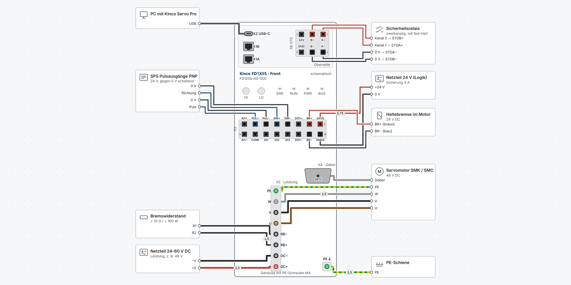
Interactive wiring diagram: DC supply and logic, motor and encoder, holding brake, braking resistor, STO, digital inputs, pulse/direction, analog setpoint, ready signal, Modbus RTU, CANopen, EtherCAT, PROFINET and USB-C, with cable cross-sections and parameters
First steps: commissioning in eleven steps, from wiring to the first motion with Kinco Servo Pro
Dimensions & mounting: dimensional drawing per model, drilling pattern, minimum clearances and a printable drilling template
Downloads: coming soon: user manual, selection manual and 2D and 3D drawings
Free support from spstiger if you get stuck
Interactive wiring diagram
Tap a terminal or wire in the drawing to see details.
Terminal overview FD1X5S
| Terminal | Group | mm² | Function |
|---|---|---|---|
| X2 USB-C | X2 | – | Debug interface for Kinco Servo Pro (KS PRO) on the PC. USB cable max. 3 m. |
| X1B | X1 | – | Second RJ45 socket, same pinout as X1A, to the next drive. |
| X1A | X1 | – | RJ45 socket with CAN, RS-485 (Modbus RTU) and the gantry bus. X1A and X1B have the same pinout and are used to daisy-chain the bus. |
| 24V | X6 | 0.2–1.5 | 24 V output from the logic supply. Only for jumpering to STOA+ and STOB+ when testing without safety equipment. |
| B+ | X6 | 0.2–1.5 | STO channel B, same values as channel A. If either channel drops out, the drive switches off the torque. |
| A+ | X6 | 0.2–1.5 | STO channel A, 24 V DC ± 15 %, 2.3 mA, IEC 61131-2 type 1. High ≥ 15 V (recommended ≥ 18 V), low ≤ 11 V (recommended ≤ 7 V). |
| GND | X6 | 0.2–1.5 | Reference for pin 3. For testing, jumper to STOA− and STOB−. |
| B− | X6 | 0.2–1.5 | Reference for STO channel B. |
| A− | X6 | 0.2–1.5 | Reference for STO channel A. |
| AI1+ | X3 | 0.2–1.5 | Analog input ±10 V, 12 bit, differential. |
| PUL+ | X3 | 0.2–1.5 | Pulse input 12–24 V, up to 500 kHz: pulse/direction, CW/CCW or A/B. Usable as digital input DI4 with 2010.1E = 1. |
| PUL− | X3 | 0.2–1.5 | Pulse input minus. |
| DIR+ | X3 | 0.2–1.5 | Direction input 12–24 V. Usable as digital input DI5 with 2010.1E = 1. |
| DIR− | X3 | 0.2–1.5 | Direction input minus. |
| DO1+ | X3 | 0.2–1.5 | Digital output, open collector, max. 30 V, 100 mA. Factory default Ready (2010.0F = 0001). |
| BR+ | X3 | 0.2–1.5 | Brake output for the holding brake, max. 500 mA. Voltage = logic supply × duty cycle (6410.11, factory 70 %). Alternatively a 24 V source or open collector. |
| 24VS | X3 | 0.2–1.5 | Logic supply 24 V (18–30 V), 500 mA plus the holding brake current, isolated from the power supply (500 V DC). Must be connected. |
| AI1− | X3 | 0.2–1.5 | Reference for the analog input. |
| COMI | X3 | 0.2–1.5 | Common terminal of DI1–DI3. The inputs are bipolar: PNP sensors with COMI to 0 V, NPN sensors with COMI to +24 V. |
| DI1 | X3 | 0.2–1.5 | Digital input, high 12.5–30 V, low 0–5 V, up to 1 kHz, 5 kΩ. |
| DI2 | X3 | 0.2–1.5 | Fast digital input, response time ≤ 10 µs, 2.7 kΩ. Suitable for fast capture (touch probe). |
| DI3 | X3 | 0.2–1.5 | Fast digital input, response time ≤ 10 µs, 2.7 kΩ. |
| DO1− | X3 | 0.2–1.5 | Emitter of DO1. The output is isolated; sourcing and sinking are both possible. |
| BR− | X3 | 0.2–1.5 | Brake output minus. |
| GNDS | X3 | 0.2–1.5 | Reference of the logic supply. |
| DB15 | X4 | – | Motor encoder via the Kinco encoder cable. Multi-turn SMK motors (Q) need the cable with battery box E-H-QY-…; for single-turn use, E-H-MV-… is sufficient. |
| PE | X5 | – | Protective earth of the motor. |
| W | X5 | – | Motor phase W. |
| V | X5 | – | Motor phase V. |
| U | X5 | – | Motor phase U. |
| RB− | X5 | – | External braking resistor. Never connect it to DC+ and DC−. |
| RB+ | X5 | – | External braking resistor. |
| DC− | X5 | – | Power supply minus. |
| DC+ | X5 | – | Power supply 24–60 V DC. Undervoltage 16 V, brake chopper from 63 V, overvoltage 70 V (factory settings). |
| PE ⏚ | PE | – | Connect the housing to the PE bar by the shortest route, more than 2 mm², at least 4 mm² for longer cables. Earth several drives in a star, not in series. |
* Clamping range not stated in the manual, derived.
First steps with the Kinco FD1X5S
From unpacking to the first motion in eleven steps: wire up, sort out STO, connect Kinco Servo Pro, read in the motor, check the inputs, jog, select the operation mode and save. You only need pulse mode, fieldbus, holding brake and braking resistor if your application uses them.
Disconnect all supplies before you plug in or clamp any cables. Voltage may still be present in the drive after switching off.
The power supply goes to DC+ and DC−, never to U, V, W. Never connect the braking resistor to DC+ and DC−.
Use PELV power supplies if you use STO (manual chap. 6.3.3). The drive belongs in a control cabinet rated at least IP54.
1Connect supply, motor and encoderRequired
Power 24–60 V DC via a fuse to DC+ and DC− (X5), logic supply 24 V to 24VS and GNDS (X3 pins 8 and 16). The logic supply must be connected on every FD1X5S.
Motor to U, V, W and PE (X5), encoder cable to X4. Connect the housing to the PE bar via the M4 earthing screw by the shortest route.
The wiring diagram shows cross-sections, fuse and circuit breaker for your model.
The power supply must ramp up steadily at switch-on (manual chap. 7.1.1). If the voltage fluctuates around the 10 V and 17 V thresholds while ramping up, the drive may start with a fault.
The continuous currents in the data sheet apply on an aluminum plate 300 × 300 × 10 mm (FD165S: 400 × 400 × 10 mm). Without the plate, the FD125S for example manages 12 instead of 15 Arms.
Show wiring “DC and logic supply”Show wiring “Motor and encoder”
Source: FD1X5S User Manual chap. 3.2, 5.1, 5.2.2, 5.3, 6.2, 7.1, 14
2STO: jumpers or safety relayRequired
Without a signal at both STO inputs (X6), the drive cannot be enabled. For the first commissioning without a safety function, jumper 24V to STOA+ and STOB+ and GND to STOA− and STOB−.
In operation with personnel protection, STOA+ and STOB+ come from two channels of a safety relay or a safety controller. If either channel drops out, the drive switches off the torque.
Parameter Value Meaning 60F7.11 0 STO_Status: both channels high, no fault STO_Status 60F7.11
Value Fault code Meaning resettable 0 — STO A and B high, no diagnostic faults — 3 0xFF1A STO A drops out, B stays high for more than 100 ms ja 5 0xFF1B STO B drops out, A stays high for more than 100 ms ja 6 0xFF10 both channels dropped out while enabled, or low when enabling ja 1, 7 0xFF21, 0xFF20 self-diagnosis or hardware fault in the STO circuit no Ratings according to the manual: SIL 3, PL e, category 3, response time below 20 ms.
STO does not disconnect the voltage. A moving axis coasts to a stop. For suspended loads, STO alone is not sufficient.
Check and document STO during commissioning, then trigger it at least every three months.
Show wiring “STO jumpered (test)”Show wiring “STO with safety relay”
Source: FD1X5S User Manual chap. 6.2.6, 6.3, tables 6-2, 6-3, fig. 7-1, 7-2
3Connect Kinco Servo ProRequired
The FD1X5S is set up with the PC software Kinco Servo Pro (KS PRO). The drive has no keypad, only LEDs.
Connect via a USB-C data cable to X2. Internally, the USB-C socket uses the RS232 protocol, so select RS232 in Servo Pro, not RS485.
How it works
Switch on power and logic supply.
In Servo Pro, open Start → Online mode.
Select the RS232 interface, choose the COM port or refresh the port list.
Click Start scanning. The drive appears in the list.
Select the drive and click Start config. Servo Pro creates a project in the process.
USB cable max. 3 m. Some USB-C charging cables connect GND to PE, which disturbs the connection. Use a USB isolator in that case.
Do not power the drive via USB only: if the connection drops while saving, the drive reports an EEPROM fault.
Alternatively, connect via X1 with an isolated RS485 converter or via CAN (PEAK-CAN). Then select RS485 or CAN in Servo Pro.
Source: FD1X5S User Manual chap. 6.2.2, 8.1, 8.2.2
4Read in the motor⚠ CautionRequired
Reread Encoder resets everything
Reread Encoder initializes the drive: all parameters return to factory default, including the station number. Export the parameters first if anything has already been set (step 11).
The Kinco SMK and SMC motors store their data in the encoder. Under Motor Config, check that the displayed motor code matches the nameplate.
If it differs, click Reread Encoder. After the restart, the motor is configured.
Parameter Value Meaning 3041.06 2 Read motor data from the encoder (factory). Must be 2 for multi-turn SMK 6410.01 Code Motor code, usually the first two characters of the serial number on the nameplate 2690.00 10 Reset encoder status and multi-turn data (fault 000.4 at first power-up) 2340.0E 1 Use the multi-turn encoder as single-turn, without battery Multi-turn motor on the drive for the first time: fault 000.4 is normal. Write 2690.00 = 10, then reset the fault or restart. Afterwards, set the position to the current value with homing method 35.
The battery sits in the encoder cable E-H-QY-…. Below 3.1 V the drive issues a warning; below 2.5 V the multi-turn data is lost (fault 000.4).
Show wiring “Motor and encoder”
Source: FD1X5S User Manual chap. 8.2.6, 9.1.2, 11.1, 13.15, 14
5Check inputs and set the rotation directionRequired
At the factory, inputs may be assigned functions for pulse mode, e.g. enable or limit switches. As long as they are active, they block enabling and jogging in Servo Pro. IO Config shows the assignment. Batch Clear removes all functions you do not need.
Then assign the functions you use, e.g. DI1 = enable. Connect limit switches as normally closed contacts: 0 means end position reached, that direction is blocked.
Parameter Value Meaning 2010.03–05 HEX Function DI1–DI3: 0001 enable, 0002 fault reset, 0010 limit switch +, 0020 limit switch −, 0040 home switch, 1000 quick stop 2010.01 HEX Polarity per input 2010.0F 0001 DO1: Ready (factory); 0002 fault, 0004 position reached 607E.00 0 / 1 Rotation direction: 0 = counterclockwise positive (factory), 1 = clockwise positive The manual contradicts itself on the factory setting of the inputs: table 13.9 gives 0000, chap. 11.2 limit switches on DIN4/DIN5, chap. 9.2 functions for pulse mode. What Servo Pro shows under IO Config is what counts.
With 2010.1E = 1, PUL and DIR can be used as digital inputs DI4 and DI5.
Show wiring “Digital inputs”Show wiring “Ready signal to PLC”
Source: FD1X5S User Manual chap. 8.2.5, 9.2, 11.2, 13.3, 13.9
6Jog mode and reversing runRequired
Under JOG you run the motor without a controller. The drive must not be enabled via an input or fieldbus, otherwise the function cannot be used.
First check that the mechanics can move freely. The first run shows whether direction and wiring are correct.
Jog
Enter the jog speed.
Click Enable.
Hold down CW or CCW. The motor turns as long as you hold the button.
If the axis oscillates or hums, stop immediately and check the controller tuning (manual chap. 12).
Source: FD1X5S User Manual chap. 9.2
7Select the operation mode and enableRequired
Set the operation mode in 6060.00. Enable via the control word 6040.00: first 0x06, then 0x0F. If an input has the enable function, the drive itself sets the control word to the value from 2020.0F (factory 0x2F).
Parameter Value Meaning 6040.00 0x06 → 0x0F Enable; 0x2F → 0x3F absolute positioning, 0x4F → 0x5F relative, 0x0F → 0x1F homing, 0x86 fault reset 607A.00 inc Target position in encoder increments Operation modes 6060.00
Value Operation mode 1 Positioning with position controller 3 Speed with ramp −3 Speed direct, without ramp 4 Torque 6 Homing −4 Pulse mode (factory) 7 Interpolation via CANopen The FD1X5S calculates positions in increments. SMK motors with a 17-bit encoder are limited internally to 65,536 increments per revolution so that the position does not overflow (manual chap. 11.1.5).
Source: FD1X5S User Manual chap. 10.1.2, 13.1, 13.3
8Pulse mode with a controllerOptional
In pulse mode (6060.00 = −4, factory default), the controller specifies pulse and direction. The PUL and DIR inputs accept 12–24 V up to 500 kHz, from PNP or NPN outputs.
The electronic gear defines how many pulses make one motor revolution: numerator / denominator = 65,536 / pulses per revolution.
Parameter Value Meaning 2508.03 1 Pulse/direction (factory); 0 = CW/CCW, 2 = A/B. Save and restart after changing 2508.01 4096 Gear numerator, manual example: 10,000 pulses per revolution 2508.02 625 Gear denominator (factory 1000/1000) 3046.00 4 Pulse filter 500 kHz (factory), must be above the pulse frequency Instead of the gear, you can also set the pulses per revolution directly: 2508.12 = 1, then 2508.11 = e.g. 10,000.
Use a shielded, twisted cable for the pulses.
Show wiring “Pulse / direction PNP”Show wiring “Pulse / direction NPN”
Source: FD1X5S User Manual chap. 7.1, 10.6.2, 13.10
9Fieldbus: station number and baud rateOptional
AS models (RS-485 and CANopen): the rotary switches HI and LO give the station number 0x00–0x7F. With HI set to C, LO sets the baud rate. Factory default: CANopen 500 kbit/s, RS-485 38,400 bit/s, Modbus RTU with 8 data bits, 1 stop bit, no parity.
ES models (EtherCAT): the rotary switches give the station alias 0x00–0xFF. Operation modes according to CiA 402: CSP, CSV, PP, PV, PT and HM.
PS models (PROFINET): no rotary switches. Supported are telegrams 1, 3, 5, 9, 102, 105, 111 and 750, IRT and DSC.
Set the rotary switches (AS, ES)
Switch off the drive. The switches are only read at power-up.
Set HI and LO with a 2–2.5 mm screwdriver.
Switch on. RUN flashes three times when the setting has been accepted.
Enter the same station number or baud rate in the controller.
At both ends of an RS-485 or CAN bus, 120 Ω between A and B or CAN_H and CAN_L.
While Servo Pro is connected via CAN, do not let other devices send CAN telegrams to the drive.
Show wiring “Modbus RTU (RS-485)”Show wiring “CANopen”Show wiring “EtherCAT”Show wiring “PROFINET”
Source: FD1X5S User Manual chap. 1.2, 6.2.1, 6.2.7, 8.2.2
10Holding brake and braking resistorOptional
The motor's holding brake connects directly to BR+ and BR− (X3 pins 7 and 15). The drive powers it from the logic supply; no separate power supply is needed. For the drive to control the brake, the motor must be configured as a motor with brake.
A braking resistor at RB+ and RB− absorbs the energy during braking. It becomes necessary when the bus voltage rises above 63 V during braking and the drive reports overvoltage (002.0).
Parameter Value Meaning 6410.17 1 Motor with brake 6410.11 70 % Duty cycle of the brake voltage, recommended 40–90 % 6410.12 150 ms Brake delay 605A.00 2 Quick stop with ramp, the brake engages only at zero speed (factory 0 = uncontrolled) 60F7.01 / .02 Ω / W Values of the braking resistor, otherwise its monitoring is off On motors with a magnetic encoder, observe the brake polarity: brown to BR+, blue to BR−. With reversed polarity it disturbs the encoder.
The minimum braking resistor values per model are in the wiring diagram; smaller values are not permitted.
Show wiring “Holding brake”Show wiring “Braking resistor”
Source: FD1X5S User Manual chap. 3.2, 7.3, 11.3, 13.13, 14
11Save and back upRequired
Changed parameters are only permanent after saving. Without saving, they are gone after the next power-off.
In addition, export the parameters in Servo Pro as a .ksparam file. Use it to restore the settings or to set up further drives the same way.
Parameter Value Meaning 2FF0.01 1 Save configuration and controller parameters (10 = reset to factory default) 2FF0.03 1 Save motor parameters 2FFF.00 0xAA55 Restart the drive Common faults
Code Fault Typical cause FFF.F Motor not configured Read in the motor again (step 4) 000.2 Encoder communication Encoder cable not plugged in or wrong motor code 000.4 Encoder internal Multi-turn data invalid, 2690.00 = 10; check the battery 002.0 Overvoltage Regeneration during braking, add a braking resistor 004.0 Undervoltage Power supply too weak or logic switched on before power 008.0 Overcurrent Short circuit at U, V, W or wrong motor data 020.0 Following error U, V, W swapped, brake not released, 6065 or 6073 too small 040.0 Logic voltage too low Check the logic supply 080.0 I²t motor or drive Overload, brake not released, mechanics stiff On a fault, the red ERR LED lights up. Servo Pro shows the fault code and the fault history.
Fix the fault first, then reset it (control word 0x86 or an input with the fault reset function).
Source: FD1X5S User Manual chap. 8.2.4.3, 13.11, 13.15, 14
Revision 1.0 · 02.10.2026 · Source: Kinco FD1X5S Servo Drive User Manual (2026-08-13), Selection Manual K1E18 (2026-09-09). The manufacturer manual and applicable standards take precedence; installation and commissioning by a qualified electrician only.
Dimensions and mounting
Dimensions and drilling pattern of the selected model for upright mounting (back against the mounting plate). Step 3 describes flat mounting on the large side face. The drawing is schematic; the dimensions come from the Kinco dimension drawings and are rounded to whole millimeters.
All models
| Item | Rating | W × H × D (mm) | Hole spacing (mm) | Hole ⌀ (mm) | Weight (kg) |
|---|---|---|---|---|---|
| FD115S-AS-000 | FD115S-AS · 5 Arms | 35 × 141 × 76 | 2 slots vertically above each other, 138 mm apart, 21 mm from the left edge | 5.5 | 0.405 |
| FD125S-AS-000 | FD125S-AS · 15 Arms | ||||
| FD115S-ES-000 | FD115S-ES · 5 Arms | ||||
| FD125S-ES-000 | FD125S-ES · 15 Arms | ||||
| FD115S-PS-000 | FD115S-PS · 5 Arms | ||||
| FD125S-PS-000 | FD125S-PS · 15 Arms | ||||
| FD135S-AS-000 | FD135S-AS · 30 Arms | 39 × 175 × 101 | 2 slots vertically above each other, 168 mm apart, 21 mm from the left edge | 5.5 | 0.695 |
| FD135S-ES-000 | FD135S-ES · 30 Arms | ||||
| FD135S-PS-000 | FD135S-PS · 30 Arms | ||||
| FD145S-AS-000 | FD145S-AS · 50 Arms | 39 × 200 × 101 | 2 slots vertically above each other, 193 mm apart, 21 mm from the left edge | 5.5 | 0.867 |
| FD145S-ES-000 | FD145S-ES · 50 Arms | ||||
| FD145S-PS-000 | FD145S-PS · 50 Arms | ||||
| FD165S-AS-000 | FD165S-AS · 80 Arms | 50 × 240 × 145 | 2 slots vertically above each other, 233 mm apart, centered | 5.5 | 1.69 |
| FD165S-ES-000 | FD165S-ES · 80 Arms | ||||
| FD165S-PS-000 | FD165S-PS · 80 Arms |
Mounting step by step
1Check the installation site
The FD1X5S has protection class IP20 (the power terminal X5 only IP00) and belongs in a control cabinet rated at least IP54.
Ambient temperature −20 to +40 °C without condensation. Above 40 °C the current must be derated.
Humidity below 90 %, without condensation.
Altitude up to 3000 m, between 1000 and 3000 m derate by 1.5 % per 100 m.
Motor and encoder cable max. 10 m, control and bus cables max. 30 m.
2Upright mounting: back against the plate
The drive stands upright with its narrow back against the mounting plate. It is fixed with two screws through the slots at the top and bottom. The drilling pattern and the drilling template above apply to this position.
FD115S/FD125S: 138 mm apart, FD135S: 168 mm, FD145S: 193 mm, FD165S: 233 mm.
Hole or slot 5.5 mm, suitable for M5.
3Flat mounting: side face against the plate
In flat mounting, the large side face lies against the mounting plate and the connections point sideways. This position uses the plate as a heat sink: the continuous currents in the data sheet apply with an aluminum plate 300 × 300 × 10 mm (FD165S: 400 × 400 × 10 mm).
Without an additional cooling plate, the FD125S manages 12 Arms, the FD135S 22 Arms, the FD145S 35 Arms and the FD165S 55 Arms.
FD115S/FD125S: 2 slots 30 mm from the back, 138 mm apart vertically.
FD135S/FD145S: 4 slots 32 mm and 70 mm from the back, 168 mm (FD135S) or 193 mm (FD145S) apart vertically.
FD165S: one slot at the top 31 mm, one hole ⌀ 5.5 mm at the bottom 96 mm from the back, 225 mm apart vertically; the hole is 12 mm above the bottom edge.
Leave 80 mm free next to the connection side and 25 mm on the other sides.
4Keep clearances and cable space
The drive needs space for ventilation and cables. Leave more distance if a braking resistor is nearby: it gets hot.
Upright: 25 mm to the wall and neighboring devices.
At the top 70 mm cable space for X1, X2 and X6, in front 80 mm for the plugs at X3, X4 and X5.
Route cables downward so that no water can run along the cable into the device.
5Earth the housing
The housing has an M4 earthing screw (at the bottom). Connect it to the PE bar by the shortest route, with more than 2 mm², at least 4 mm² for longer cables. Earth several drives in a star, not in series.
Mount the drive and line filter on the same highly conductive, earthed metal plate.
Revision 1.0 · 02.10.2026 · Source: Kinco dimension drawings FD1X5S (FD115S–FD165S, AS/ES and PS), FD1X5S User Manual (2026-08-13) chap. 1.1.4 and 5.1. The manufacturer manual and applicable standards take precedence; installation by a qualified electrician only.
Stuck?
Our support helps you free of charge. Tell us what you are planning and which model you use – via the contact form, by email or in the community forum.
Contact formEmail support@spstiger.deAsk in the community forum
More ways to contact us: Support contacts
We have compiled and checked this page carefully from the manufacturer’s documentation. Even so, an error may have slipped in. The manufacturer’s manual and the applicable standards always take precedence. Spotted something? Let us know – we’ll be glad to fix it.
Downloads
User manual, selection manual and 2D and 3D drawings will be available here shortly. Until then, we are happy to send them to you – just use the contact form.