


INVT GD27 – Support, Wiring Diagram & Commissioning
Everything for your INVT GD27 after purchase – for all ten models from 0.4 to 7.5 kW, single-phase 230 V and three-phase 400 V:
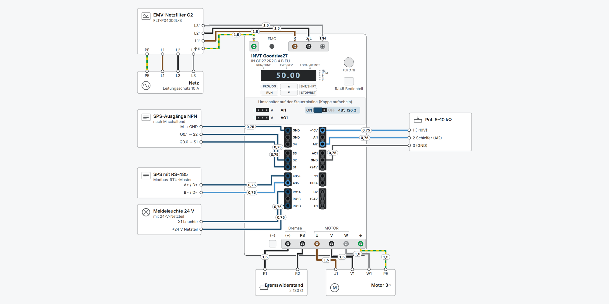
Interactive wiring diagram: mains and motor, STO, start/stop, setpoint, Modbus RTU, relay and braking resistor, with cable cross-sections and parameters
First steps: commissioning in ten steps, from the motor data to the first run
Operation: keypad simulator to try out, with exercises
Dimensions & mounting: dimensional drawing per model, drilling pattern, minimum clearances and a printable drilling template
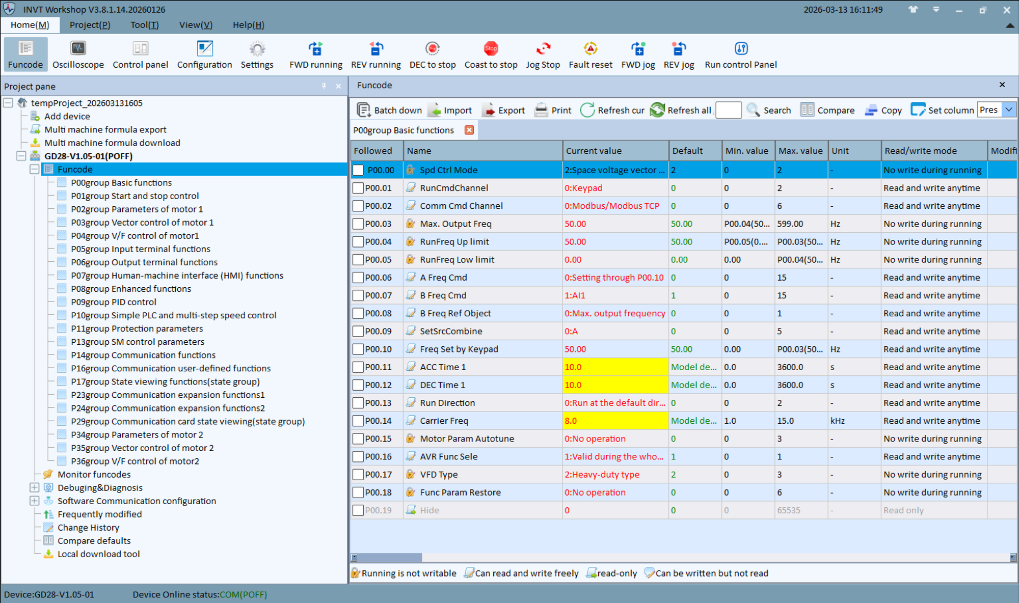
Downloads: user manual (English) and Workshop software
Free support from spstiger if you get stuck
Keypad: keys, display and LEDs
PRG/JOG opens the menu for setting parameters – the most important key for programming. Try out the keypad here: set parameters, start and stop the motor, reset faults. The exercises guide you step by step through the most important procedures. Rest the mouse pointer on a key for a moment to see what it does right now.
Interactive wiring diagram
Tap a terminal or wire in the drawing to see details.
Terminal overview GD27
| Terminal | Group | mm² | Function |
|---|---|---|---|
| ⏚ | ERDE | – | Input grounding terminal at the top left. Each device has two PE terminals (mains and motor); connect both (chap. 4.4.2). Leakage current above 3.5 mA: grounding resistance below 10 Ω, PE conductor with the same conductivity as the phase conductor (chap. 1.4). |
| R | NETZ | – | Mains L1 (3~). On 1~ models, R stays free: the terminal marking R · S/L · T/N (fig. in chap. 4.4.2) assigns L and N to the terminals S/L and T/N. The terminal table, however, lists “R/L, S, T/N” – check the marking on the device before connecting. |
| S / S/L / S/L | NETZ | – | Mains L2 (3~) or L (1~). Up to 4 kW the terminal is called S/L, at 5.5 and 7.5 kW S. |
| T / T/N / T/N | NETZ | – | Mains L3 (3~) or N (1~). Up to 4 kW the terminal is called T/N, at 5.5 and 7.5 kW T. |
| GND | XL1 | – | Reference for +24V and the digital inputs. The inputs S1–S4 and HDIA switch to GND: the GD27 supports NPN only (chap. 4.5.3.1). Also the reference for RS-485 (fig. 7-1). |
| GND | XL1 | – | Second GND terminal of the left terminal block, same potential. |
| S4 | XL1 | – | Factory: P05.04 = 0 (no function). |
| S3 | XL2 | – | Factory: P05.03 = 7 (fault reset). |
| S2 | XL2 | – | Factory: P05.02 = 4 (jog forward). For reverse, set P05.02 = 2. |
| S1 | XL2 | – | Factory: P05.01 = 1 (forward). Level high 16–30 V, low 0–2 V, up to 1 kHz. Only NPN can be connected: contact between S1 and GND, the supply is internal (fig. 4-11). |
| 485+ | XL3 | – | RS-485 A (Modbus RTU). Shielded twisted pair. 120 Ω termination resistor can be switched in with the 485 switch. |
| 485− | XL3 | – | RS-485 B. |
| RO1A | XL4 | – | NO contact of RO1, 3 A / AC 250 V or 1 A / DC 30 V. Function via P06.03 (factory 1 = running). The EU models have RO1 only; the STO terminals sit in place of RO2. |
| RO1B | XL4 | – | NC contact of RO1. |
| RO1C | XL4 | – | Common terminal of RO1. |
| +10V | XR1 | – | Reference voltage 10 V for a setpoint potentiometer. The manual gives neither the load capacity nor the potentiometer value. |
| AI1 | XR1 | – | 0–10 V or 0–20 mA. Set the AI1 switch (pry off the plastic cap) and P05.52 (0 = voltage, 1 = current) to match. 20 mA corresponds internally to 10 V. |
| AI2 | XR1 | – | 0–10 V, voltage only. |
| AO1 | XR2 | – | 0–10 V or 0–20 mA, AO1 switch. Function via P06.14 (factory 0 = running frequency). |
| GND | XR2 | – | GND terminal of the right terminal block, reference for +10V, AI1, AI2, AO1 and +24V. Same potential as the GND terminals on the left. |
| +24V | XR2 | – | Internal 24 V, max. 100 mA, for digital signals, Y1 and small sensors. |
| Y1 | XR3 | – | Open collector to GND, 50 mA / 30 V, up to 1 kHz. Function via P06.01 (factory 0 = no function). Load between +24V and Y1 (fig. 4-12) or with an external 12–24 V DC supply (fig. 4-9). |
| HDIA | XR3 | – | Pulse input up to 50 kHz (duty cycle 30–70 %, factory P05.00 = 0). With P05.00 = 1 normal digital input, function via P05.09. Switches to GND like S1–S4. |
| H2 | XR4 | – | Second channel of safe torque off. Linked to +24V on delivery. |
| +24V | XR4 | – | 24 V ±15 % for the STO inputs. Linked to H1 and H2 on delivery (appendix E.4). |
| H1 | XR4 | – | NC contact between +24V and H1. Open = STO active, display E40. STO acts at 0–5 V and is released at 13–30 V, input current 5 mA (appendix E.5). |
| (+) | LEISTUNG | – | DC link plus, braking resistor between (+) and PB. The (−) terminal to its left cannot be used on standard and EU models (chap. 4.4.2). |
| PB | LEISTUNG | – | The brake chopper is built into all GD27-…-B; only the resistor is external. Enable with P08.37 = 1. |
| U | LEISTUNG | – | Motor output U. |
| V | LEISTUNG | – | Motor output V. |
| W | LEISTUNG | – | Motor output W. |
| ⏚ | LEISTUNG | – | Output grounding terminal at the bottom of the device for the protective conductor of the motor cable. Ground the protective conductor at the VFD and at the motor (chap. 4.4.2). |
* Clamping range not stated in the manual, derived.
First steps with the INVT GD27
Ten steps from unboxing to the first motor run: connect, clarify STO, enter motor data, set start/stop and setpoint, adjust ramps. You only need digital inputs, Modbus and the braking resistor if your application uses them.
Disconnect all supplies and wait at least 5 minutes (manual, all GD27 models). Only then touch the terminals.
Always connect the protective earth (PE) first. Never apply mains voltage to U, V, W.
STO is jumpered at the factory and therefore inactive. If you use STO as a safety function, you need a risk assessment and an acceptance test according to manual appendix E (step 2).
1Connect mains and motorRequired
Mains to R, S, T (single-phase S2 models: L, N on the terminals R/L and T/N), motor to U, V, W. Connect the green-yellow protective conductor of the mains cable and of the motor cable to the respective grounding terminal.
The wiring diagram shows the cross-sections and fuse protection for your model. Route the motor cable, mains cable and control cables separately.
The manual recommends symmetrical motor cables; ground the protective conductor of the motor cable at the VFD and at the motor.
Maximum motor cable length in normal operation: 50 m (frame A), 75 m (B), 150 m (C). Beyond these lengths, an output reactor close to the VFD is required. EMC category C3 allows at most 10 m of shielded motor cable, C2 (S2 models only) 5 m.
The EU models have a built-in EMC filter. In an IT network, in a TT network without grounded neutral and in a TN network with a grounded phase conductor, remove the EMC screw; otherwise tripping or damage may occur.
Wrong rotation direction: P00.13 = 1 or swap two motor phases. P00.13 = 2 disables reverse running.
Show wiring “Mains and motor”Show wiring “Mains with EMC filter”
Practise on the keypad: “Switch the rotation direction with PRG/JOG”
Source: GD27 Manual V1.1 chap. 1.4, 4.2, 4.4, A.5, P00.13
2STO: factory jumper or safety circuitRequired
On delivery, +24V–H1 and +24V–H2 are jumpered. The VFD runs, but STO is not a safety function.
For STO, remove the jumpers and wire two NC contacts of a safety relay, a safety PLC or an emergency stop switch into the circuits +24V–H1 and +24V–H2. Both contacts must open or close together within 200 ms.
Parameter Value Meaning P08.64 1 Enable STO function – factory default 0 = off; according to the manual, set to 1 on devices with STO P08.52 0 0 = STO signal E40 latched, reset required (factory default); 1 = signal clears automatically P06.01 29 Y1 signals “STO triggered”, e.g. as feedback to the safety controller Displays
Display Meaning E40 STO triggered: H1 and H2 open – reset with STOP/RST E41 / E42 Channel H1 / H2 faulty (only one channel open) – can only be reset after mains off/on E43 both channels faulty, hardware fault in the STO circuit The manual does not state whether shutdown via H1/H2 also works with P08.64 = 0. If you use STO, therefore set P08.64 = 1 and verify the function with the acceptance test.
Ratings according to the manual: SIL 2, category 3, PFH 8.53 · 10⁻¹⁰, DC > 90 %. The manual gives no PL value. Cable double-shielded and twisted, at most 25 m, shield to PE.
STO does not replace an emergency stop and does not disconnect the supply. Carry out and document the acceptance test according to the checklist in appendix E.8 at first commissioning and after every change.
Show wiring “STO (Safe Torque Off)”
Practise on the keypad: “Reset STO message E40”
Source: GD27 Manual V1.1 chap. 4.5.2, 6.12.6, appendix E, P06.01, P08.52, P08.64, fault list chap. 8.2.1
3Enter motor data and motor auto-tuningRequired
The values are on the motor's rating plate. The parameters of group P02 can only be changed at standstill. For synchronous motors, set P02.00 = 1 and enter the data in P02.15–P02.19.
Parameter Value Meaning P02.00 0 Motor type: 0 = asynchronous motor (factory default), 1 = synchronous motor P02.01 Rating plate Rated power in kW P02.02 Rating plate Rated frequency, factory default 50.00 Hz P02.03 Rating plate Rated speed in min⁻¹ P02.04 Rating plate Rated voltage in V P02.05 Rating plate Rated current in A P00.00 0, 1 or 2 Control mode: 2 = SVPWM (V/f, factory default), 0 = SVC 0, 1 = SVC 1 (sensorless vector control, only after auto-tuning) Motor auto-tuning
P00.01 = 0 (start via the keypad).
Enter P02.01 to P02.05 from the rating plate.
Select P00.15: 1 = rotating (disconnect the motor from the load), 2 = static complete, 3 = static partial (P02.06–P02.08 only). Confirm with ENT/SHIFT.
Start with RUN. During autotuning, the RUN/TUNE LED blinks; at the end, the VFD stops automatically.
With P00.15 = 2 or 3, the load does not have to be disconnected.
Fault E20: motor power does not match VFD power (more than five power ratings apart), wrong rating plate data or timeout. Check the data, disconnect the load, start again.
Practise on the keypad: “Enter motor data and motor auto-tuning”
Source: GD27 Manual V1.1 chap. 5.1.1, 6, 6.1, 6.2, P00.00, P00.15, P02, fault list E20
4Set the start/stop sourceRequired
P00.01 defines where the start command comes from. The digital inputs work in NPN wiring only with internal supply: the contact is between Sx and GND.
Parameter Value Meaning P00.01 0 / 1 / 2 0 = keypad (factory default), 1 = terminals, 2 = communication P05.01 1 S1 = forward (factory default) P05.02 2 S2 = reverse – factory default is 4 = jog forward P05.13 0 Two-wire control 1 (factory default); 2 and 3 = three-wire control with Sin P07.04 0–3 Effect of the STOP/RST key with terminal or communication control (factory 0 = keypad only) A PLC with PNP outputs (switching +24 V) cannot drive the inputs directly, because the manual provides for NPN wiring only. In that case, use interface relays or outputs switching to minus (derived).
S3 is fault reset by default (P05.03 = 7). The terminal functions P05.01–P05.09 can only be changed at standstill; two inputs must not have the same function.
LOCAL/REMOT shows the command source: off = keypad, flashing = terminals, on = communication.
Show wiring “Start/stop via switch”Show wiring “Start/stop from PLC (NPN)”
Practise on the keypad: “Start and stop the motor from the keypad”Practise on the keypad: “Switch the running command to terminals”
Source: GD27 Manual V1.1 chap. 4.5.3.1, 5.1.1, 6.3, 6.9.1.1, P00.01, P05, P07.04
5Set the setpointRequired
Parameter Value Meaning P00.06 0 / 1 / 2 / 3 / 8 Frequency setpoint A: 0 = P00.10 (factory), 1 = AI1, 2 = AI2, 3 = AI3 (keypad potentiometer), 8 = Modbus P00.10 50.00 Hz Frequency setting via the keypad (factory) P00.03 50.00 Hz Maximum output frequency, reference for setpoints and ramps (only at standstill) P00.04 / P00.05 50.00 / 0.00 Hz Upper and lower limit of the running frequency P05.52 0 / 1 Signal type AI1: 0 = voltage (factory), 1 = current P05.32 / P05.34 0.00 / 10.00 V Lower and upper limit AI1 (factory) AI1 accepts 0–10 V or 0–20 mA. For current, change both: set the AI1 DIP switch (pry off the plastic cover) to “I” and P05.52 = 1. 20 mA corresponds internally to 10 V. AI2 accepts 0–10 V only.
For 4–20 mA on AI1: P05.32 = 2.00 V (4 mA, calculated from 20 mA ≙ 10 V).
100 % analog setpoint corresponds to P00.03. The keypad potentiometer works as AI3 (P05.53 = 0). Analog cables shielded and twisted, at most 20 m.
Show wiring “Setpoint via potentiometer”Show wiring “Setpoint 4–20 mA from PLC”
Practise on the keypad: “Set frequency P00.10 to 15.00 Hz”Practise on the keypad: “Setpoint via the potentiometer (AI3)”
Source: GD27 Manual V1.1 chap. 4.5.2, 4.5.3.2, 5.1.3, 6.4.2, 6.9.2.1, P00.03–P00.10, P05.32–P05.53
6Set acceleration and deceleration timeOptional
Parameter Value Meaning P00.11 model-dependent Acceleration time 1 from 0 Hz to P00.03 (0.0–3600.0 s) P00.12 model-dependent Deceleration time 1 from P00.03 to 0 Hz P01.08 0 / 1 Stop mode: 0 = ramp (factory default), 1 = coast to stop A deceleration time that is too short with a large flywheel mass leads to E8 (overvoltage during deceleration). Then extend the deceleration time or connect a braking resistor (step 9).
The overvoltage stall protection P11.03 is switched on at the factory (1) and extends the ramp when the DC link voltage rises.
Four ramp pairs can be selected via two digital inputs (function 21/22): P00.11/P00.12, P08.00/P08.01, P08.02/P08.03, P08.04/P08.05.
Practise on the keypad: “Set acceleration time P00.11 to 5.0 s”
Source: GD27 Manual V1.1 chap. 6.7.2, 6.9.1.1, 6.12.1, P00.11–P00.12, P01.08, P11.03, fault list E8
7Assign digital inputs and relaysOptional
Factory defaults
Terminal Parameter Factory Meaning S1 P05.01 1 Forward S2 P05.02 4 Jog forward S3 P05.03 7 Fault reset S4 P05.04 0 no function HDIA P05.00 0 Pulse input; with 1 normal digital input (function P05.09) Y1 P06.01 0 no function; 1 = running, 29 = STO triggered RO1 P06.03 1 running Further input functions: 2 = reverse, 3 = three-wire run control, 6 = coast to stop, 9 = external fault, 16–19 = multi-step speed terminals 1–4 (function list in manual chap. 6.9.1.1).
Preset speeds: with the terminals for function 16–19 you select up to 16 steps. The values are in P10.02 (step 0), P10.04 (step 1), P10.06 (step 2) etc. in % of P00.03. If all multi-step speed terminals are open, the setpoint from P00.06 applies.
The EU models have only relay RO1 (3 A / 250 V AC, 1 A / 30 V DC), and in return the STO terminals H1/H2. Y1 is an open-collector output for 50 mA / 30 V.
Show wiring “Fault signal via relay”Show wiring “Run signal to PLC (Y1)”Show wiring “Preset speeds via switches”
Practise on the keypad: “Switch the running command to terminals”
Source: GD27 Manual V1.1 chap. 2.2, 4.5.2, 6.4.2.5, 6.9.1, P05.00–P05.09, P06.01–P06.04, P10.02
8Configure Modbus RTUOptional
Parameter Value Meaning P00.01 2 Run command via communication P00.06 8 Frequency setpoint via Modbus (on the GD28 it would be 10) P14.00 1 Slave address (factory, 1–247) P14.01 4 19200 bit/s (factory) P14.02 1 E, 8, 1 RTU (factory) P14.04 0.0 s Timeout off (factory); otherwise fault E18 if telegrams stop arriving Control word 2000H (8192): 0001H = forward, 0005H = stop, 0007H = fault reset. Frequency setpoint 2001H (8193) in 0.01 Hz: 50 Hz = 5000 = 1388H (calculated).
Parameter address = group and number in hex, e.g. P05.06 → 0506H, P10.01 → 0A01H. For frequent writing without EEPROM wear, set the highest bit (RAM, write only), e.g. P00.07 → 8007H.
You switch in the 120 Ω bus termination with the “485” DIP switch – only at the two ends of the bus. Use shielded twisted cable.
Show wiring “Modbus RTU to PLC”
Source: GD27 Manual V1.1 chap. 4.5.2, 6.10, 7.2.1, 7.2.2, 7.3.1, P14
9Connect a braking resistorOptional
All GD27 models with -B in the name have the brake chopper built in. The resistor is external and goes between (+) and PB.
Parameter Value Meaning P08.37 1 Enable dynamic braking – factory default 0 = off P08.38 700.0 V Switch-on threshold 400 V models (230 V models: 380.0 V) P11.03 0 Overvoltage stall protection off – according to the manual when operating with a braking resistor Never go below the minimum resistance from manual table D-7. The wiring diagram shows the values per model.
With P11.02 = 1, the chopper also brakes at standstill, otherwise only during operation. It switches off when the DC link voltage falls 10 V below P08.38.
Without P08.37 = 1, the resistor stays cold. Fault E23: braking circuit faulty or resistor too small.
Show wiring “Braking resistor”
Practise on the keypad: “Reset fault E8”
Source: GD27 Manual V1.1 chap. 2.1, 4.4, 6.12.1, 6.12.5, D.3.3, P08.37–P08.38, P11.02–P11.03, fault list E23
10First runRequired
Group P17 provides the operating values (e.g. P17.01 output frequency, P17.04 output current, P17.11 DC link voltage, P17.12 digital input status), P07.27–P07.32 the fault memory.
Reset faults: STOP/RST, digital input with function 7, or mains off/on.
Restore factory settings: P00.18 = 1 (without motor parameters; also deletes the user password). P00.18 = 2 clears the fault memory.
Practise on the keypad: “Start and stop the motor from the keypad”Practise on the keypad: “Read operating values (P17) and fault memory (P07)”
Source: GD27 Manual V1.1 chap. 5.1.3, 6, 6.11, 8.1, P00.18, P07.02, P07.27, P08.06, P17
Revision 1.0 · 29.09.2026 · Source: INVT Goodrive27 Series Smart VFD Manual V1.1 (09/2023). The manufacturer manual and applicable standards take precedence; installation and commissioning by a qualified electrician only.
Dimensions and mounting
Dimensions and drilling pattern of the selected model. The drawing is schematic; the dimensions are taken from the manual.
All models
| Item | Rating | W × H × D (mm) | Hole spacing (mm) | Hole ⌀ (mm) | Weight (kg) |
|---|---|---|---|---|---|
| IN.GD27.0R4G.S2.B.EU | 0.4 kW · 1~ 230 V | 60 × 190 × 155 | 2 holes one above the other, 180 mm apart, 36 mm from the right edge | 5 | 0.99 |
| IN.GD27.0R7G.S2.B.EU | 0.75 kW · 1~ 230 V | ||||
| IN.GD27.0R7G.4.B.EU | 0.75 kW · 3~ 400 V | ||||
| IN.GD27.1R5G.4.B.EU | 1.5 kW · 3~ 400 V | ||||
| IN.GD27.1R5G.S2.B.EU | 1.5 kW · 1~ 230 V | 70 × 190 × 155 | 2 holes one above the other, 180 mm apart, 36 mm from the right edge | 5 | 1.25 |
| IN.GD27.2R2G.S2.B.EU | 2.2 kW · 1~ 230 V | ||||
| IN.GD27.2R2G.4.B.EU | 2.2 kW · 3~ 400 V | ||||
| IN.GD27.004G.4.B.EU | 4 kW · 3~ 400 V | ||||
| IN.GD27.5R5G.4.B.EU | 5.5 kW · 3~ 400 V | 90 × 235 × 155 | 70 × 220 | 6 | 1.95 |
| IN.GD27.7R5G.4.B.EU | 7.5 kW · 3~ 400 V |
Mounting step by step
1Check the installation site
The GD27 belongs in a clean, well-ventilated indoor location, usually a control cabinet (manual chap. 3.2.1).
Ambient temperature −10 to +50 °C, without rapid temperature changes.
Humidity below 90 %, non-condensing; with corrosive gases at most 60 %.
Vibration at most 5.8 m/s² (0.6 g).
No direct sunlight, no oil mist, metal or conductive dust, no water; do not mount on a combustible surface.
Installation altitude up to 1000 m without derating, above that 1 % per 100 m; above 3000 m consult the manufacturer.
2Keep the minimum clearances
Cooling air flows through the unit from bottom to top. To let it enter and leave freely, the drive needs space to walls, cable ducts and neighbouring devices.
At least 40 mm at the sides, at least 100 mm at the top and bottom (manual tables 3-1 and 3-2).
Several VFDs side by side with the same clearances; align devices of different sizes at the top edge.
3Mark and drill the holes
Frames A and B (up to 4 kW) each have one lug at the top and bottom, 36 mm from the right edge: a hole at the top, a slot open towards the edge at the bottom. Frame C (5.5 and 7.5 kW) has four holes, closed at the top, open at the bottom (manual Figs. C-1 and C-2).
The manual does not give the edge distance at the top and bottom. In the drawing and the drilling template, the holes are assumed centred between the edges. The manual does not give a screw size; Ø 5 mm suits M4, Ø 6 mm suits M5 (derived).
The 1:1 drilling template helps with marking out. Print it at actual size (100 %) and check the 100 mm reference length with a ruler.
4Mount vertically
The GD27 may only be mounted vertically. First pre-fit the upper screws, hang the VFD on them, then insert the lower screws and tighten all of them (manual chap. 3.3.1.1). The weight is listed with the dimensions.
Frames A and B can also be mounted on a DIN rail with the DIN rail holder (order no. 11091-00014) (manual chap. 3.3.1.2 and D.3.4.3).
5Keypad in the cabinet door (optional)
An external keypad is available for all models. It can be mounted in the cabinet door directly with two screws or in one of the two mounting frames (manual appendix D.3.4).
Keypad: 56 × 75 × 31 mm.
Directly on the door: 2 holes ⌀ 4.5 mm and a 19 × 19 mm cut-out, position see manual Fig. D-5.
Mounting frame 1 (61001-00090): 66 × 87 mm, door cut-out 63 × 83 mm.
Mounting frame 2 (11022-00136): 88 × 124 mm, door cut-out 82 × 115 mm.
6Connect
Then connect mains, motor and PE. Cross-sections and fusing per model are shown in the wiring diagram.
Revision 1.0 · 29.09.2026 · Source: GD27 Manual V1.1 (09/2023), chap. 2.5, 3.2, 3.3, appendices C.1 and D.3.4: tables 3-1, 3-3, C-1, C-2, Figs. C-1, C-2, D-4 to D-8. The manufacturer manual and applicable standards take precedence; installation by a qualified electrician only.
Stuck?
Our support helps you free of charge. Tell us what you are planning and which model you use – via the contact form, by email or in the community forum.
Contact formEmail support@spstiger.deAsk in the community forum
More ways to contact us: Support contacts
We have compiled and checked this page carefully from the manufacturer’s documentation. Even so, an error may have slipped in. The manufacturer’s manual and the applicable standards always take precedence. Spotted something? Let us know – we’ll be glad to fix it.
Downloads
User manual (English) and Workshop software:
INVT GD27 frequency inverters
Compatible software