



INVT GD20 – Support, Wiring Diagram & Commissioning
Everything for your INVT GD20 after purchase – for all ten models from 0.4 to 11 kW, single-phase 230 V and three-phase 400 V:
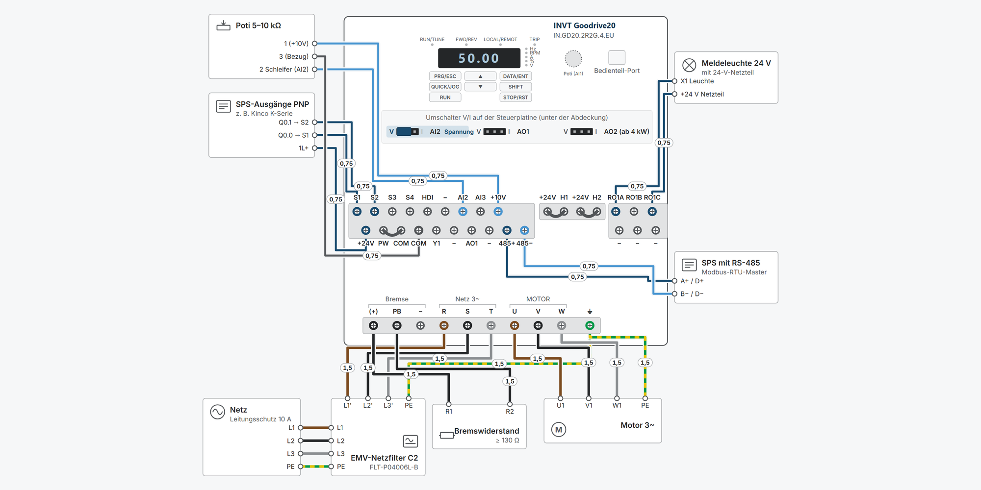
Interactive wiring diagram: mains and motor, STO, start/stop, setpoint, Modbus RTU, relay and braking resistor, with cable cross-sections and parameters
First steps: commissioning in ten steps, from the motor data to the first run
Operation: keypad simulator to try out, with exercises
Dimensions & mounting: dimensional drawing per model, drilling pattern, minimum clearances and a printable drilling template
Downloads: user manual (German and English), catalogue and technical data sheet
Free support from spstiger if you get stuck
Keypad: keys, display and LEDs
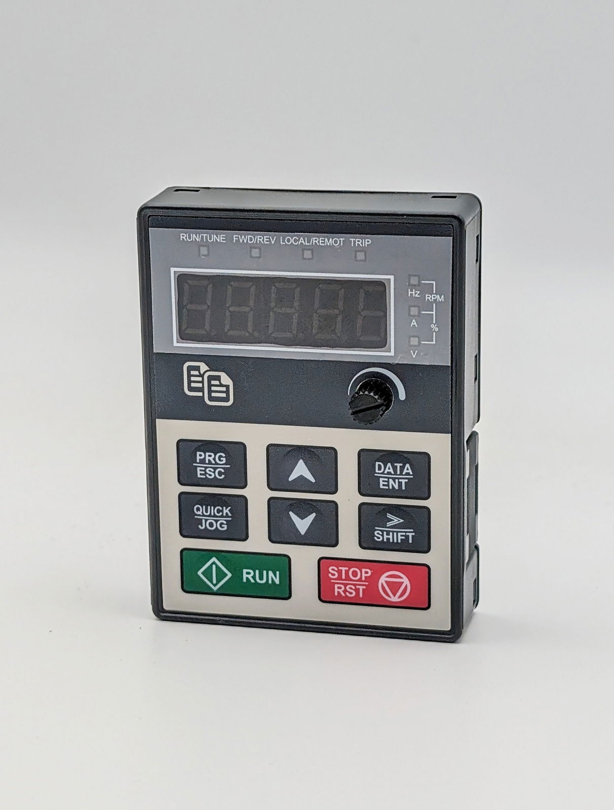
PRG/ESC opens the menu for setting parameters – the most important key for programming. Try out the keypad here: set parameters, start and stop the motor, reset faults. The exercises guide you step by step through the most important procedures. Rest the mouse pointer on a key for a moment to see what it does right now.
Interactive wiring diagram
Tap a terminal or wire in the drawing to see details.
Terminal overview GD20
| Terminal | Group | mm² | Function |
|---|---|---|---|
| S1 | STEUER | – | 12–30 V, input resistance 3.3 kΩ, up to 1 kHz. Factory: P05.01 = 1 (forward). |
| S2 | STEUER | – | Factory: P05.02 = 4 (jog forward). For reverse, set P05.02 = 2. |
| S3 | STEUER | – | Factory: P05.03 = 7 (fault reset). |
| S4 | STEUER | – | Factory: P05.04 = 0 (no function). |
| HDI | STEUER | – | Pulse input up to 50 kHz (duty cycle 30–70 %). With P05.00 = 1 normal digital input, function then via P05.09. |
| Y1 / – / – | STEUER | – | From 4 kW, Y1 is in the upper row between HDI and AI2. Open collector via optocoupler to COM, 30 V / 50 mA, up to 1 kHz. Function via P06.01. |
| AI2 | STEUER | – | 0–10 V (20 kΩ) or 0–20 mA (500 Ω), AI2 switch on the control board. 20 mA corresponds internally to 10 V. |
| AI3 | STEUER | – | −10–+10 V, voltage input. |
| +10V | STEUER | – | Reference voltage 10 V, max. 50 mA, for a setpoint potentiometer of 5 kΩ or more. |
| +24V | STEUER | – | Internal 24 V ±10 %, max. 200 mA, for digital inputs, Y1 and small sensors. |
| PW | STEUER | – | Selects PNP/NPN and internal/external supply via U-shaped jumper. Factory: jumper PW–COM = PNP with internal supply. NPN internal: jumper PW–+24V. |
| COM | STEUER | – | Reference of +24V and the digital signals. |
| COM | STEUER | – | Second COM terminal. On 1~ 230 V and 3~ 400 V up to 2.2 kW, COM is also the reference for +10V, AI2, AI3 and AO1 (no separate GND terminal). |
| – / Y1 / Y1 | STEUER | – | On 1~ 230 V and 3~ 400 V up to 2.2 kW, Y1 is in the lower row between COM and AO1; from 4 kW this position is empty. Open collector to COM, 30 V / 50 mA, up to 1 kHz. Function via P06.01. |
| GND / – / – | STEUER | – | From 4 kW only: reference for +10V, AI2, AI3, AO1 and AO2. Empty up to 2.2 kW, analog reference there at COM. |
| AO1 | STEUER | – | 0–10 V or 0–20 mA, AO1 switch. Function via P06.14 (factory 0 = output frequency). |
| AO2 / – / – | STEUER | – | From 4 kW only. Function via P06.15. |
| 485+ | STEUER | – | RS-485 A (Modbus RTU/ASCII). Shielded twisted pair, 120 Ω termination resistor external. |
| 485− | STEUER | – | RS-485 B. |
| +24V | STO | – | Supplies STO input H1. Linked to H1 on delivery. |
| H1 | STO | – | Safe torque off channel 1, NC contact between +24V and H1. Open = STO active. Linked on delivery. |
| +24V | STO | – | Supplies STO input H2. Linked to H2 on delivery. |
| H2 | STO | – | Second, redundant channel. Both contacts must open or close together within 250 ms. |
| RO1A | RELAIS | – | NO contact of RO1, AC 250 V / 3 A or DC 30 V / 1 A. Function via P06.03 (factory 1 = running). Up to 2.2 kW, the RO1 terminals are to the right of the STO terminals (RO1B/RO1C top, RO1A/RO1C bottom); from 4 kW, to the left of the control terminals (RO1 top, RO2 bottom). The drawing is schematic. |
| RO1B | RELAIS | – | NC contact of RO1. |
| RO1C | RELAIS | – | Common terminal of RO1. Up to 2.2 kW, RO1C is provided twice. |
| RO2A / – / – | RELAIS | – | From 4 kW only. Function via P06.04 (factory 5 = fault). |
| RO2B / – / – | RELAIS | – | From 4 kW only. |
| RO2C / – / – | RELAIS | – | From 4 kW only. |
| (+) | LEISTUNG | – | DC link plus, braking resistor between (+) and PB. |
| PB | LEISTUNG | – | The brake chopper is built into all models up to 37 kW; only the resistor is external. Enable with P08.37 = 1. |
| (−) / – / – | LEISTUNG | – | From 4 kW only, for an external braking unit or DC bus. Not for the braking resistor. |
| R / L | LEISTUNG | – | Mains L1 (3~) or L (1~ 230 V). |
| S / N | LEISTUNG | – | Mains L2 or N (1~ 230 V). |
| T / – | LEISTUNG | – | Mains L3, 3~ models only. |
| U | LEISTUNG | – | Motor output U. |
| V | LEISTUNG | – | Motor output V. |
| W | LEISTUNG | – | Motor output W. |
| ⏚ | LEISTUNG | – | Protective earth. Up to 2.2 kW the last terminal of the power terminal block, from 4 kW a separate earthing terminal on the housing (Fig. 3-6 does not show PE in the terminal block). |
* Clamping range not stated in the manual, derived.
First steps with the INVT GD20
Ten steps from unboxing to the first motor run: connect, clarify STO, enter motor data, set start/stop and setpoint, adjust ramps. You only need digital inputs, Modbus and the braking resistor if your application uses them.
Disconnect all supplies and wait at least 5 minutes (manual, all GD20 models) or until the DC link voltage is below 36 V. Only then touch the terminals.
Always connect the protective earth (PE) first. Never apply mains voltage to U, V, W.
STO is jumpered at the factory and therefore inactive. If you use STO as a safety function, you need a risk assessment and a test according to the STO checklist in the manual (step 2).
1Connect mains and motorRequired
Mains to R, S, T (single-phase S2 models: L, N), motor to U, V, W, PE to the earthing terminal. Connect the protective conductor of both the mains cable and the motor cable to PE.
The wiring diagram shows the cross-sections and fuse protection for your model. Route the motor cable, mains cable and control cables separately.
The manual requires symmetrical, shielded motor cables. From a cable length of 50 m between inverter and motor, an output reactor is required; with several motors, the total cable length counts.
The internal C3 filter of the models from 4 kW (400 V) or from 1.5 kW (3~ 230 V) is connected via plug-in jumper J10. In an IT network, or if the residual current device trips at power-on, disconnect J10.
Wrong rotation direction: P00.13 = 1 or swap two motor phases.
Source: GD20-EU Manual V1.9 chap. 1.3, 3.2.1–3.2.3, C.5, C.6.2
2STO: factory jumper or safety circuitRequired
On delivery, +24V–H1 and +24V–H2 are connected with U-shaped jumpers. The inverter runs, but STO is not a safety function.
For STO, remove the jumpers and wire two NC contacts of a safety relay or emergency stop into the circuits +24V–H1 and +24V–H2. Both contacts must open or close together within 250 ms.
Parameter Value Meaning P11.16 0x000 Hundreds digit 0 = STO signal latched, reset required (factory default); 1 = signal clears automatically P06.01 27 Y1 signals “STO triggered”, e.g. as feedback to the safety controller Displays
Display Meaning STO STO triggered: H1 and H2 open STL1 / STL2 Channel H1 / H2 faulty (only one channel open) – cannot be reset STL3 internal circuit faulty – cannot be reset CrCE CRC error in the FLASH of the safety code – contact the manufacturer After the channels close, the inverter needs a new start command, even if the signal clears automatically.
Ratings according to the manual: SIL 2, PL d, category 3 for the small frame sizes (1~ 230 V, 3~ 230 V up to 0.75 kW, 3~ 400 V up to 2.2 kW); SIL 3, PL e, category 3 for the larger ones. Proof test interval 1 year (SIL 2) or 3 months (SIL 3). Cable shielded, max. 25 m.
STO does not replace an emergency stop and does not disconnect the supply. Carry out and document the test according to the STO checklist (manual chap. 3.3.3) at first commissioning.
Show wiring “STO (Safe Torque Off)”
Practise on the keypad: “Reset the STO signal”
Source: GD20-EU Manual V1.9 chap. 2.2, 2.7, 3.2.5, 3.3, P11.16, fault list chap. 6.2.3
3Enter motor data and motor auto-tuningRequired
The values are on the motor's rating plate. The parameters of group P02 can only be changed at standstill.
Parameter Value Meaning P02.01 Rating plate Rated power in kW P02.02 Rating plate Rated frequency, factory default 50.00 Hz P02.03 Rating plate Rated speed in min⁻¹ P02.04 Rating plate Rated voltage in V P02.05 Rating plate Rated current in A P00.00 0, 1 or 2 Control mode: 2 = SVPWM (V/f, factory default), 0 = SVC 0, 1 = SVC 1 (sensorless vector control, only after auto-tuning) Motor auto-tuning
P00.01 = 0 (start via the keypad).
Enter P02.01 to P02.05 from the rating plate.
Select P00.15: 1 = rotating (uncouple the motor from the load), 2 = static complete, 3 = static partial (P02.06–P02.08 only). Confirm with DATA/ENT.
Start with RUN. During auto-tuning, the RUN/TUNE LED flashes.
P00.15 then returns to 0; the determined motor parameters are saved.
The manual does not describe the key sequence for auto-tuning step by step; starting with RUN and the reset of P00.15 are taken from the INVT operating concept.
Fault tE: motor does not match the inverter power, rating plate data wrong or timeout. Check the data, uncouple the load.
Practise on the keypad: “Enter motor data and motor auto-tuning”
Source: GD20-EU Manual V1.9 chap. 2.1.5, 4.1, P00.00, P00.15, P02, fault list tE
4Set the start/stop sourceRequired
P00.01 determines where the start command comes from. The digital inputs are jumpered at the factory for PNP with internal supply (U-shaped jumper COM–PW): the contact is between +24V and Sx. For NPN, move the jumper to +24V–PW.
Parameter Value Meaning P00.01 0 / 1 / 2 0 = keypad (factory default), 1 = terminals, 2 = communication P05.01 1 S1 = forward (factory default) P05.02 2 S2 = reverse – factory default is 4 = jog forward P07.04 0–3 Effect of the STOP/RST key with terminal or communication control (factory 0 = keypad only) S3 is fault reset at the factory (P05.03 = 7). The terminal functions P05.01–P05.04 can only be changed at standstill.
LOCAL/REMOT shows the command source: off = keypad, flashing = terminals, on = communication.
Show wiring “Start/stop via switch”Show wiring “Start/stop from PLC (PNP)”
Practise on the keypad: “Start and stop the motor from the keypad”Practise on the keypad: “Switch the run command to terminals”
Source: GD20-EU Manual V1.9 chap. 3.2.5, 3.2.6, 4.1, P00.01, P05, P07.04
5Set the setpointRequired
Parameter Value Meaning P00.06 0 / 1 / 2 / 3 / 8 Frequency setpoint A: 0 = P00.10 (factory), 1 = AI1 (keypad potentiometer), 2 = AI2, 3 = AI3 (−10 … +10 V), 8 = Modbus P00.10 50.00 Hz Frequency setting via the keypad (factory) P00.03 50.00 Hz Maximum output frequency, reference for setpoints and ramps (only at standstill) P00.04 / P00.05 50.00 / 0.00 Hz Upper and lower limit of the running frequency P05.37 / P05.39 0.00 / 10.00 V Lower and upper limit of AI2 (factory) You switch AI2 between 0–10 V and 0–20 mA with a plug-in jumper; there is no parameter for this. 20 mA corresponds internally to 10 V.
For 4–20 mA at AI2: jumper to current, P05.37 = 2.00 V (4 mA, calculated from 20 mA ≙ 10 V).
100 % analog setpoint corresponds to P00.03. The keypad potentiometer works as AI1.
Show wiring “Setpoint via potentiometer”Show wiring “Setpoint 4–20 mA from PLC”
Practise on the keypad: “Set frequency P00.10 to 15.00 Hz”Practise on the keypad: “Setpoint via the potentiometer (AI1)”
Source: GD20-EU Manual V1.9 chap. 3.2.5, 4.1, P00.03–P00.10, P05.32–P05.44
6Set acceleration and deceleration timeOptional
Parameter Value Meaning P00.11 model-dependent Acceleration time 1 from 0 Hz to P00.03 (0.0–3600.0 s) P00.12 model-dependent Deceleration time 1 from P00.03 to 0 Hz A deceleration time that is too short with a large flywheel mass leads to OV2 (overvoltage during deceleration). Then extend the deceleration time or connect a braking resistor (step 9).
The overvoltage stall protection P11.03 is switched on at the factory (1) and extends the ramp when the DC link voltage rises.
Practise on the keypad: “Set acceleration time P00.11 to 5.0 s”
Source: GD20-EU Manual V1.9 chap. 2.1.5, P00.11–P00.12, P11.03, fault list OV2
7Assign digital inputs and relaysOptional
Factory defaults
Terminal Parameter Factory Meaning S1 P05.01 1 Forward S2 P05.02 4 Jog forward S3 P05.03 7 Fault reset S4 P05.04 0 no function HDI P05.00 0 Pulse input; with 1 normal digital input (function P05.09) Y1 P06.01 0 no function; 27 = STO triggered RO1 P06.03 1 running RO2 P06.04 5 Inverter in fault state Further functions: 2 = reverse, 3 = three-wire control, 16–19 = multi-step speed terminals 1–4, 42 = quick stop (function list 0–42 in the manual).
RO2 and AO2 are only available from 4 kW (400 V) or 1.5 kW (3~ 230 V); the small models only have RO1. Relays: 3 A / 250 V AC, 1 A / 30 V DC.
Y1 is a transistor output for 50 mA / 30 V.
Show wiring “Fault signal via relay”Show wiring “Run signal to PLC (Y1)”
Source: GD20-EU Manual V1.9 chap. 3.2.5, P05.00–P05.09, P06.01–P06.04
8Configure Modbus RTUOptional
Parameter Value Meaning P00.01 2 Run command via communication P00.06 8 Frequency setpoint via Modbus (on the GD28 it would be 10) P14.00 1 Slave address (factory, 1–247) P14.01 4 19200 bit/s (factory) P14.02 1 E, 8, 1 RTU (factory) P14.04 0.0 s Timeout off (factory); otherwise fault CE when telegrams are missing Control word 2000H (8192): 0001H = forward, 0005H = stop, 0007H = fault reset. Frequency setpoint 2001H (8193) in 0.01 Hz: 10 Hz = 03E8H (manual example), 50 Hz = 5000 = 1388H (calculated).
Parameter address = group and number in hex, e.g. P05.05 → 0505H. For frequent writing without EEPROM wear, set the highest bit (RAM, write only), e.g. P00.07 → 8007H.
The GD20 has no internal bus termination. Fit a 120 Ω resistor between 485+ and 485− at each end of the bus.
Show wiring “Modbus RTU to PLC”
Source: GD20-EU Manual V1.9 chap. 7.2.1, 7.4.1, 7.4.2, 7.5.3, P14
9Connect a braking resistorOptional
The brake chopper is built in up to 37 kW; at 45–110 kW only in the models with -B. The resistor is always external and goes between (+) and PB.
Parameter Value Meaning P08.37 1 Enable dynamic braking – factory default 0 = off P08.38 700.0 V Switch-on threshold 400 V models (230 V models: 380.0 V) Never go below the minimum resistance from manual Tab. C.7.1, otherwise the chopper will be destroyed. The wiring diagram shows the values for each model.
Remove the yellow warning labels on PB, (+) and (−) before connecting, otherwise the contact will be poor. Cable to the resistor shielded.
Without P08.37 = 1, the resistor stays cold; the inverter then extends the ramp via the overvoltage stall protection (P11.03).
Show wiring “Braking resistor”
Practise on the keypad: “Reset fault OV2”
Source: GD20-EU Manual V1.9 chap. 2.6, 3.2.1, 3.2.2, C.7, P08.37–P08.38
10First runRequired
Group P17 provides the operating values (e.g. P17.01 output frequency, P17.04 output current, P17.11 DC link voltage), the fault memory is at P07.27 ff.
Restore factory settings: P00.18 = 1 (without motor parameters) or 6 (with motor parameters).
Practise on the keypad: “Start and stop the motor from the keypad”Practise on the keypad: “Read operating values (P17) and fault memory (P07)”
Source: GD20-EU Manual V1.9 chap. 2.1.4, 2.1.5, 4.3.3, P00.18, P07.02, P07.27, P17
Revision 1.0 · 29.09.2026 · Source: INVT Goodrive20-EU VFD Manual V1.9 (main source), German manual GD20-EU V1.8 (terminology), GD20-EU Technical Datasheet. The manufacturer manual and applicable standards take precedence; installation and commissioning by a qualified electrician only.
Dimensions and mounting
Dimensions and drilling pattern of the selected model. The drawing is schematic; the dimensions are taken from the manual.
All models
| Item | Rating | W × H × D (mm) | Hole spacing (mm) | Hole ⌀ (mm) | Weight (kg) |
|---|---|---|---|---|---|
| IN.GD20.0R4G.S2.EU | 0.4 kW · 1~ 230 V | 80 × 160 × 124 | 60 × 150 | 5 | 0.9 |
| IN.GD20.0R7G.S2.EU | 0.75 kW · 1~ 230 V | ||||
| IN.GD20.1R5G.S2.EU | 1.5 kW · 1~ 230 V | 80 × 185 × 141 | 60 × 175 | 5 | 1.2 (S2) / 1.0 (4) |
| IN.GD20.2R2G.S2.EU | 2.2 kW · 1~ 230 V | ||||
| IN.GD20.1R5G.4.EU | 1.5 kW · 3~ 400 V | ||||
| IN.GD20.2R2G.4.EU | 2.2 kW · 3~ 400 V | ||||
| IN.GD20.004G.4.EU | 4 kW · 3~ 400 V | 146 × 256 × 167 | 131 × 244 | 6 | 3.1 |
| IN.GD20.5R5G.4.EU | 5.5 kW · 3~ 400 V | ||||
| IN.GD20.7R5G.4.EU | 7.5 kW · 3~ 400 V | 170 × 320 × 196 | 151 × 304 | 6 | 5.58 |
| IN.GD20.011G.4.EU | 11 kW · 3~ 400 V |
Mounting step by step
1Check the installation site
The GD20 belongs in a well-ventilated indoor area, usually in a control cabinet (protection class IP20).
Ambient temperature −10 to +50 °C. Above 40 °C, derate by 1 % per kelvin; above 50 °C not recommended.
Vibration at most 5.8 m/s² (0.6 g).
No direct sunlight, no oil or salt mist, no corrosive or flammable gases, no metal dust.
Installation altitude up to 1000 m without derating, above that 1 % per 100 m; above 3000 m consult the manufacturer.
2Keep the minimum clearances
The cooling air flows through the unit from bottom to top. Space must therefore remain above and below it (manual Fig. 3-1). The manual gives no minimum lateral clearance.
At least 100 mm above and below.
3Mark and drill the holes
The GD20 is fastened with four screws. The drawing shows hole spacing and hole diameter for the selected model (manual appendix B). The manual gives no screw size for wall mounting; M4 fits Ø 5 mm, M5 fits Ø 6 mm (derived).
The 1:1 drilling template helps with marking out. Print it at actual size (100 %) and check the 100 mm reference length with a ruler.
4Mount vertically
Mount the inverter vertically: mark the hole positions, fit the screws, place the unit, tighten the screws (manual chap. 3.1.3). The weight is given with the dimensions.
The small frame sizes up to 2.2 kW can also be mounted on a DIN rail. From 4 kW, a flange frame is available as an accessory, with which the heat sink extends outwards through the mounting plate (manual Figs. 3-2 and B-9).
5Keypad in the cabinet door (optional)
The keypad can be mounted remotely in the cabinet door: directly with two screws or in one of the two mounting frames (manual appendix B.1). Up to 2.2 kW this requires an external keypad; from 4 kW the built-in one can be removed.
Keypad: 56 × 75 × 31 mm.
Directly on the door: 2 holes ⌀ 4.5 mm and a cut-out 19 × 19 mm, position see manual Fig. B-2.
Mounting frame 1: 66 × 87 mm, door cut-out 63 × 83 mm.
Mounting frame 2: 88 × 124 mm, door cut-out 82 × 115 mm.
Show mounting frame in the drawingKeypad for the GD20 in the Shop
6Connect
Then connect mains, motor and PE. Cross-sections and fusing per model are shown in the wiring diagram.
Revision 1.0 · 29.09.2026 · Source: GD20-EU Manual V1.9, chap. 3.1 and appendix B: Figs. 3-1, 3-2, B-1 to B-6. The manufacturer manual and applicable standards take precedence; installation by a qualified electrician only.
Stuck?
Our support helps you free of charge. Tell us what you are planning and which model you use – via the contact form, by email or in the community forum.
Contact formEmail support@spstiger.deAsk in the community forum
More ways to contact us: Support contacts
We have compiled and checked this page carefully from the manufacturer’s documentation. Even so, an error may have slipped in. The manufacturer’s manual and the applicable standards always take precedence. Spotted something? Let us know – we’ll be glad to fix it.
Downloads
User manual (German and English), catalogue and technical data sheet:
INVT GD20 frequency inverters
Compatible software
Accessories