


Frequency Inverter · Quick Start Guide
Kinco KC200 – First-Time Setup
Step-by-step commissioning guide for the Kinco KC200. Covers motor setup, control source, Modbus RTU, and the built-in brake chopper.
V/F · SVC · FVC
Modbus RTU · CANopen
Brake chopper built-in (≤ 45 kW)
6× DI · 2× AI std. · 2× DO · 2× Relay
Safety Notice Before Commissioning
Disconnect all poles of the mains supply before wiring and secure against unintentional reconnection.
After switching off, wait at least 10 minutes for the DC bus to discharge — hazardous voltages remain
on the DC terminals after power-off.
Do not open the inverter. Connect motor cables only when the unit is de-energised.
The full manual (KC200 Series General Vector Inverter User Manual) must be read before commissioning.
Group F03 – Motor Parameters (Nameplate Data)
| Parameter | Name | Value to Set | Description |
|---|---|---|---|
| F03.00 | Motor type | 0 | 0 = Asynchronous motor (standard) |
| F03.02 | Rated power | Nameplate kW | Rated motor power in kW |
| F03.03 | Rated voltage | Nameplate V | e.g. 230 V or 400 V |
| F03.04 | Rated current | Nameplate A | Rated motor current in A |
| F03.05 | Rated frequency | 50.00 Hz | Typically 50 Hz |
| F03.06 | Rated speed | Nameplate rpm | e.g. 1460 rpm (4-pole, 50 Hz motor) |
| F03.09 | Motor auto-tuning | 1 | 1 = Static auto-tuning (motor may remain connected, does not rotate). Recommended for SVC mode. |
Group F01 – Control Mode
| Parameter | Name | Value to Set | Description |
|---|---|---|---|
| F01.02 | Motor control mode | 0 or 1 | 0 = V/F control (simple, no auto-tuning required); 1 = SVC sensorless (recommended for better torque) |
Rule of thumb: Always enter nameplate data first, then run auto-tuning
(
F03.09 = 1) — only then activate SVC mode (F01.02 = 1).
Auto-tuning significantly improves starting torque and speed accuracy.
F01.03 – Operation Command Source (Run/Stop)
0
Keypad — Run/Stop via RUN/STOP keys on the unit
Factory default — ideal for test operation and initial commissioning
Factory default — ideal for test operation and initial commissioning
1
Terminal I/O — Run/Stop via DI terminals (e.g. DI1 = FWD, DI2 = REV)
Typical for machine/plant control with PLC or switches
Typical for machine/plant control with PLC or switches
2
Communication — Run/Stop via Modbus RTU or CANopen
For bus control: control word at address
For bus control: control word at address
0x7000
F01.04 – Main Frequency Source X (Setpoint Source)
0
Keypad digital — Frequency set via
Factory default
F01.10 or ▲/▼ keysFactory default
1
Analog input AI — 0–10 V or 0/4–20 mA at AI1 or AI2
Terminal AI1 (0–10 V / 0–20 mA) or AI2 (−10–10 V / 0–20 mA)
Terminal AI1 (0–10 V / 0–20 mA) or AI2 (−10–10 V / 0–20 mA)
4
Keypad potentiometer — Built-in potentiometer on the keypad unit
5
Communication — Setpoint via Modbus RTU or CANopen
Frequency setpoint at address
Frequency setpoint at address
0x7010 (0–10000 = 0–100 % of F01.11)
8
Multi-speed — Up to 16 fixed speeds via DI combination
Configure fixed frequencies in group F17
Configure fixed frequencies in group F17
Frequency limits: Maximum output frequency:
F01.11 (default 50 Hz).
Upper limit: F01.13. Lower limit: F01.14.
Group F01 – Acceleration Times
| Parameter | Name | Typical Value | Description |
|---|---|---|---|
| F01.21 | Ramp reference frequency | 50.00 Hz | Reference frequency for acc/dec times (default: max. frequency) |
| F01.23 | Acceleration time 1 | 10.0 s | Time from 0 Hz to F01.21. ≤5.5 kW: 10 s; 11–45 kW: 20 s; ≥55 kW: 50 s |
| F01.24 | Deceleration time 1 | 10.0 s | Time from F01.21 to 0 Hz. Same as acceleration time 1. |
Tip: Short deceleration times can cause DC bus overvoltage.
For frequent braking or high inertia loads, activate the built-in brake chopper
(→ Step 7) and connect a braking resistor to RB+ /
RB−.
Control Terminals — Overview KC200
| Terminal | Function | Note |
|---|---|---|
| +24V | +24 V supply output | Max. 200 mA; internally connected to COM |
| COM | Common ground for DI | Reference potential DI1–DI5 |
| DI1 | Digital input 1 | Default: Forward run FWD (F08.00 = 1) |
| DI2 | Digital input 2 | Default: Reverse run REV (F08.01 = 2) |
| DI3 | Digital input 3 | Freely assignable (F08.02) |
| DI4 | Digital input 4 | Freely assignable (F08.03) |
| DI5 | Digital input 5 | Freely assignable (F08.04) |
| DI6 | Digital input 6 / High-speed pulse input | Up to 100 kHz as pulse input (F08.05 = 47); freely assignable |
| +10V | +10 V reference voltage | For potentiometer at AI1/AI2 |
| AI1 | Analog input 1 | 0–10 V or 0–20 mA (jumper) |
| AI2 | Analog input 2 | −10–10 V or 0–20 mA (jumper) |
| GND | Ground for AI/AO | Analog reference potential |
| DO1 | Digital output 1 (open-collector) | Freely assignable (F10.00); 24 V / 50 mA |
| DO2 | Digital output 2 / High-speed pulse output | Up to 50 kHz as pulse output (F10.05 = 1); freely assignable |
| TA · TB · TC | Relay 1 | Changeover; AC 250 V / 3 A (F10.02) |
| TA1 · TB1 · TC1 | Relay 2 | Changeover; AC 250 V / 3 A (F10.03) |
| A+ · B− | RS-485 Modbus RTU | Group F14; also CANopen (F14.20–F14.25) |
Group F08 – Digital Input Functions
| Parameter | Terminal | Common Assignment | Value → Function |
|---|---|---|---|
| F08.00 | DI1 | Forward run | 1 = FWD (2-wire type 1) |
| F08.01 | DI2 | Reverse run | 2 = REV |
| F08.02 | DI3 | Fault reset | 9 = Fault reset |
| F08.03 | DI4 | Coast stop | 7 = Coast stop (free run) |
| F08.04 | DI5 | Freely assignable | 0 = No function |
| F08.05 | DI6 | Freely assignable | 0 = No function; 47 = High-speed pulse input (up to 100 kHz) |
| F08.10 | — | Terminal operating mode | 0 = 2-wire type 1 (default: DI1=FWD, DI2=REV) |
Note — Jumper position: Terminal OP serves as
the common reference and is connected internally to +24V by default (PNP logic).
For NPN logic (external supply, common +24V): change the jumper position on the device —
refer to the wiring section of the manual.
Group F14 – Communication Parameters
| Parameter | Name | Typical Value | Description |
|---|---|---|---|
| F14.03 | Slave address | 1 | Unique device address on the bus (1–247); default: 1 |
| F14.01 | Baud rate | 5 | 5 = 38400 bps (default); 3 = 9600; 4 = 19200; 7 = 115200 |
| F14.02 | Parity / stop bits | 0 | 0 = N,8,1 (no parity, 1 stop bit); 3 = N,8,2 |
| F14.04 | Response delay | 2 ms | Minimum delay before response; 0–20 ms |
| F01.03 | Control source | 2 | 2 = Communication (for Modbus control) |
| F01.04 | Frequency source | 5 | 5 = Communication (for Modbus setpoint) |
Key Holding Registers (Control / Read)
| Name | Hex Address | Dec. Address | Value (Hex) | Value (Dec) | Meaning |
|---|---|---|---|---|---|
| Control command (control word) | 0x7000 | 28672 | 0x0001 | 1 | Start forward run (FWD) |
| Control command (control word) | 0x7000 | 28672 | 0x0002 | 2 | Start reverse run (REV) |
| Control command (control word) | 0x7000 | 28672 | 0x0003 | 3 | Jog mode forward (JOG FWD) |
| Control command (control word) | 0x7000 | 28672 | 0x0004 | 4 | Jog mode reverse (JOG REV) |
| Control command (control word) | 0x7000 | 28672 | 0x0005 | 5 | Ramp stop (controlled) |
| Control command (control word) | 0x7000 | 28672 | 0x0006 | 6 | Emergency stop |
| Control command (control word) | 0x7000 | 28672 | 0x0007 | 7 | Coast stop (free run) |
| Control command (control word) | 0x7000 | 28672 | 0x0008 | 8 | Fault reset |
| Frequency setpoint (for writing) | 0x7010 | 28688 | 0x2710 | 10000 | 100 % of max. frequency (F01.11). Resolution: 0–10000 = 0–100 % of F01.11. Prerequisite: F01.04 = 5 |
| Current fault status (for reading) | 0x6F00 | 28416 | — | — | Current fault code of the inverter (see fault code table) |
Termination resistor: Connect a 120 Ω termination resistor between
A+ and B− at the last device on the RS-485 bus.
Modbus function code 03 for reading, 06 for writing single registers.
KC200 models ≤ 45 kW only: The KC200 has a built-in brake chopper only up to and including 45 kW.
For units > 45 kW an external brake chopper is required.
Disconnect mains power before connecting the braking resistor.
Group F13 – Brake Chopper Parameters
| Parameter | Name | Recommended Value | Description |
|---|---|---|---|
| F13.17 | Brake chopper activation voltage | 700 V | DC bus voltage threshold at which the chopper activates. Default for 380 V mains: 700 V |
| F13.18 | Brake chopper duty cycle | 100.0 % | Maximum on-time ratio of the chopper in %. Select based on braking resistor datasheet. |
Braking Resistor Terminals
| Terminal | Function | Note |
|---|---|---|
| RB+ | Braking resistor terminal + | Connect external braking resistor between RB+ and RB− |
| RB− | Braking resistor terminal − | Keep cable as short as possible (< 5 m recommended) |
Sizing: Select the braking resistor according to the Kinco manual (braking resistor appendix)
or based on braking power and duty cycle requirements.
Do not choose a resistance value that is too low — excessive braking current will damage the built-in chopper.
Complete all items before first start
Fault display: Fault codes appear as
Err.XX on the display.
Common codes: Err.01 = Overcurrent during acceleration; Err.07 = Overvoltage;
Err.09 = Undervoltage; Err.11 = Motor overload.
Full fault list: KC200 Manual, fault diagnosis chapter.

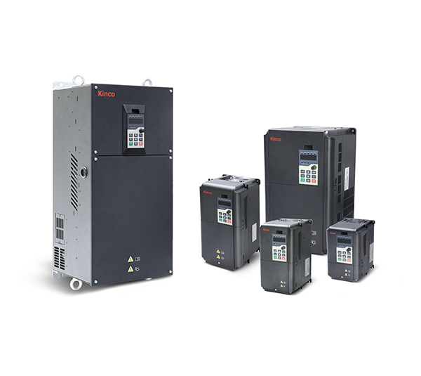
Kinco frequency inverter KC200-4T- three-phase 400 VAC
From
€153.68 *
Very powerful three-phase 400 VAC, 50Hz/60Hz frequency inverter in the 22 kW version with many convenient functions for controlling drives.Single-phase refers to the mains voltage, the motor connection is three-phase. The frequency inverter offers many convenient functions for this price range, in particular vector control without encoder and optional vector control with encoder (with correspondingly retrofitted card for speed feedback) as well as integrated filter and brake unit.
V/F control, vector control
Very simple wiring thanks to screw terminals on the front
Suitable for MODBUS via RS-485
Available in 30 days, delivery time 3 bis 5 Tage
Preis exkl. MwSt., zzgl. Versandkosten

KC Driver software for parameterizing Kinco frequency inverters of the KC100 and KC200 series
KC Driver is the software for parameterizing Kinco frequency inverters of the KC100 and KC200 series.The software supports the following functions:Connecting to the KC100 and KC200 frequency inverters via RS-485Displaying and changing the current parameters of the frequency inverterImport and export of parameter setsScoping function, for recording load curves and other characteristic curves of the frequency invertersThe frequency inverters of the KC100 and KC200 series can be parameterized via:this software via RS-485 two-wire connectionon the device itself via the control panelvia an external control panel (parameter copy function)via Modbus RTU