


Timer
The timers are located in the memory area T0 ... T639. The timers are further subdivided as follows:
- T0 ... T99 - 100 ms cycle, non-accumulating
- T100 ... T199 - 100 ms cycle, accumulating
- T200 ... T299 - 10 ms cycle, non-accumulating
- T300 ... T399 - 10 ms cycle, accumulating
- T400 ... T499 - 1 ms cycle, non-accumulating
- T500 ... T599 - 1 ms cycle, accumulating
- T600 ... T639 - 1 ms cycle, precision timer
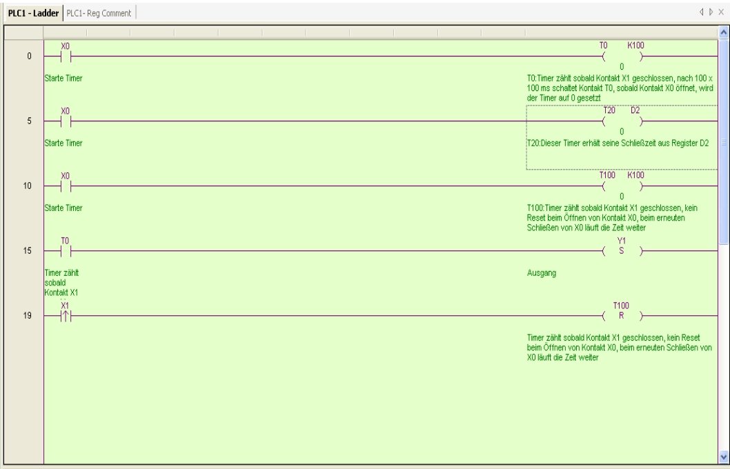
Timers are easy to program in XCPPro. An input contact activates the timer, via OUT T... K... you transfer a parameter that specifies the time after which the contact T... should close. The parameter can also be transferred via a data register D... can also be transferred. The timer runs as long as the input contact is present. After the set time has elapsed, the contact T.... closes In our example on the right, T0 closes when X0 is applied for 100 x 100 ms, i.e. after 10 seconds.
The difference between non-accumulating and accumulating timers is that the non-accumulating timers are reset to 0 as soon as the input contact is no longer present. Accumulating timers, on the other hand, stop and continue to run when the input is present again. Timers T0 to T599 are linear 16-bit timers that count up to 32767 and then stop as long as they are not reset.
There are two ways to start a timer, either via OUT (e.g. OUT T0 K100) or TMR (e.g. TMR T0 K100). While a timer activated with OUT starts immediately, a timer activated with TMR only starts at the beginning of the next PLC cycle. A difference of a few milliseconds, which can sometimes be relevant. A timer can be reset at any time with RST.
Via the address DT... you have direct access to the current status of the timer as a word. DT0 is therefore the current status of timer T0. This address can also be easily read out via the HMI.
In contrast to the normal 16-bit timers in the range T0 to T599, the precision timers in the range T600 to T639 are 32-bit timers. They therefore also occupy two addresses per timer, i.e. T600 and T601 for precision timer 1. They work at 1 millisecond intervals and can count up to 2,147,483,647, which is slightly more than 24 days. The precision timers can be used like normal timers, but also have their own command set. The timer is started as a precision timer via an edge on STR T6xx Kxx. The parameter can also be transferred via register D instead of K. As this is a 32-bit timer, the PLC takes two registers for the parameter, i.e. the content of D0 and D1 when D0 is transferred. When the preset time is reached, the timer stops and closes its contact T6xx. A new edge on the precision timer automatically triggers a reset. While the timer is running, STRR T6xx can be used to read out the current status of the timer, which is stored in TD6xx. STRS T6xx stops the timer before the set time is reached. It can be reset manually with RST.
Counter
The counters are located in the memory area C0 ... C639. They are further subdivided as follows:
- C0 ... C299 - 16 bit counting upwards
- C300 ... C499 - 32-bit up / down counting; note that a 32-bit counter occupies two addresses, counter C300 i.e. C300 and C301, therefore only ever use even counter addresses in this area
- C500 ... C599 - 32 bit up-counting; Attention, a 32 bit counter occupies two addresses, counter C500 therefore C500 and C501, therefore only ever use even counter addresses in this range
- C600 ... C619 - 32-bit single-phase high-speed counters (HSC)
- C620 ... C629 - 32-bit high-speed counters with directional input (HSC)
- C630 ... C639 - 32 bit two-phase AB counters (HSC)
Counters are also easy to implement. If an input contact closes, the counter counts up by one. Counters and timers are activated via OUT C... K... or OUT C... D.... You transfer a parameter directly as K... or indirectly via a D register a parameter that specifies the counter reading at which contact C... should close. For OUT C0 K10, contact C0 closes after its input has been closed 10 times.
16-bit counters count up to 32,767 and then stop. They are reset via RST. In the default setting, the counters are battery-buffered from C320 onwards. This value can be adjusted by setting the retentive ranges (see chapter 3); if required, you can even configure all counters as retentive.
32-bit counters can assume values between -2,147,483,648 and +2,147,483,647. Remember that two D registers are passed as parameters, so OUT C300 D0 passes D0 and D1 as parameters. Counters C300 to C498 can be switched between counting backwards and forwards via system bit M8238. M8238=0 is preset and means counting upwards, M8238=1 means counting downwards. The setting applies to all counters in this range. The 32-bit counters C500 to C599 remain unaffected. The 32-bit counters are loop counters and jump from +2,147,483,647 to -2,147,483,648 and continue counting. The reverse is true for down counters.
Counters can be reset via RST. The counters are then set to 0 and the counter outputs are opened.
Exercise
Implements an accumulating timer that closes after one second and is activated by marker M1. When the second is reached, the timer is reset with RST. A counter counts how often the timer has accumulated a second and after 3 accumulated seconds it switches output Y2.
