


The program control
- Jump labels and subroutines
- Groupings
- FOR NEXT loops
- Step controls with status bits
- Sequence controls with sequence blocks
- Interrupts
Jump labels and subroutines
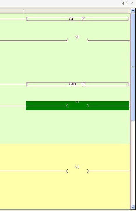
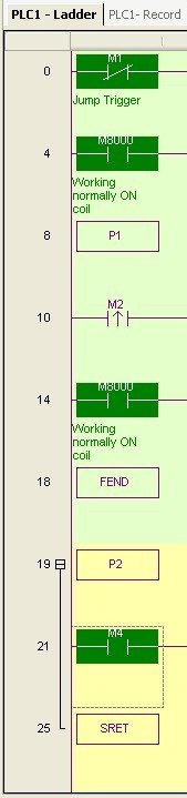
Jump labels are named P in the XC series, P0 to P9999 are freely available. There are two ways to jump to jump labels, once via CJ (conditional jump) and once via CALL (subroutine call). Both commands are called via any contact. CJ jumps directly to the jump label and continues executing the program there. The command is suitable for skipping certain areas to shorten the cycle time.
With CALL a marker P is called as a subroutine, at the end of the subroutine an SRET is set to return to the main program. The content between subroutines can be collapsed in XCPPro using a minus sign to the left of the marker. This makes the program clearer. Important: To ensure that the subroutines are not executed without being called with CALL, the main program must be ended with FEND before the subroutine section begins. FEND marks the end of the main program and the cycle starts again. The same applies to interrupt routines, which must also be in the area after FEND, otherwise they will be executed without an interrupt (see below).
In the example on the right, line 4 is skipped as long as M1 is open. Area P2 is only executed if a positive edge is present on M2.
Groupings
Lines that belong together in terms of content can be logically grouped together in the ladder diagram with the GROUP marker and the GROUPE end marker. Instructions in a group can be collapsed to increase clarity. Groupings have no influence at all on the program flow.
FOR NEXT loops
Simple counting loops can be implemented in XC with For Next loops. A positive or negative edge activates the loop. The number of passes is passed as a constant or via a D register as a parameter. Next ends the loop. Counting loops can be nested up to 8 levels deep.
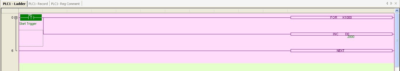 Example: Simple counting loop, a positive edge on M1 causes the loop to run 1000 times, each run increases D0 by one.
Step control with status bits
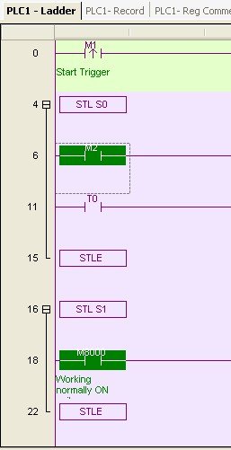
To implement simple step controls, there is a separate memory area with S0 to S1023. The associated commands are SET, ST, STL and STLE. STL S.. marks the start of the corresponding subroutine in the ladder diagram, STLE ends it. STL S0 therefore marks the area where the instructions for step S0 begin. There are two ways to activate the execution of this step. SET S0 activates step S0 and deactivates the previously active step. For example, if I call S0 from S3, SET S0 activates step S0 and deactivates S3. The command ST S0, on the other hand, activates S0 without deactivating the previously active step. This allows several steps to be executed simultaneously.
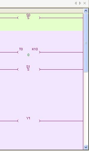
Example: Simple step control, M1 activates the step chain, step S0 activates step S1 with a 1 second delay.
Sequence control with sequence blocks
To execute standardized sequences sequentially, XCPPro offers specially designed sequence blocks. Step chains whose steps are to be executed one after the other are easier to configure in Sequence Blocks. When using the status bits described above, a separate section would have to be created for each step and the jumps inserted manually. This is much easier in Sequence Blocks. By right-clicking on Sequence Blocks in the project tree on the left, you have the option of adding such a block with Add Sequence Block. In the block itself, you can now add the various steps via Add:
- Common Item - creates a step in IL, conditions can also be implemented within the IL text
- Pulse Output - outputs a pattern of output pulses
- Modbus Item - a really easy way to carry out Modbus communication in XCPPro, more on this in the Communication chapter
- Frequency Inverter Item - allows an instruction to be sent to an FI
- Free Format Communication Item - enables simple serial communication via the RS232/RS485 interface
- Wait Item - implements a wait instruction that either waits for a flag or sets one of the timers (see chapter Timers & counters for the timers)
The Skip attribute can be used to set a bit with which the instruction is skipped. The sequence of steps can be changed via Upwards & Downwards. The steps are executed one after the other. The end of one step initiates the next; there are no transition conditions in the sequence blocks. The step control with status bits described above is suitable for conditional sequences.
Interrupts
In THINGET XC controllers, there are three options for executing instructions with high priority via interrupts: Time interrupts, interrupts via precision timers and input interrupts. Interrupts interrupt the normal program flow and execute instructions immediately when certain events occur. This allows particularly time-critical actions to be executed. In the main program, you can define which areas may and may not be interrupted by interrupts. EI (enable interrupts) allows interrupts. This is also the default setting. DI (disable interrupts) can be used to mark areas that are so important that they must not be interrupted. At the end of this area, you can allow interrupts again via EI.
Normal time interrupts are particularly easy to implement. There are ten of these interrupts, I40** to I49**. They are simply implemented using the I40nn instruction, where nn stands for the interrupt time in ms. This is followed by the instructions that are to be executed by this interrupt. This area is terminated with IRET. I4150 therefore executes the following code every 50 ms as a time interrupt. For the first three interrupts I40... to I42... there are additional bits with markers M8056 to M8058, which can switch these interrupts on and off.
The precision timer interrupts allow particularly reliable and precise time control, even for periods of more than 100 ms. The ten precision timers are between T600 to T618, you have learned how they work in the Timers & Counters chapter. The precision timer interrupts can be implemented via I3000 to I3010. These interrupt instructions are also terminated with IRET. Example: if the precision timer contact T602 switches, the interrupt routine between I3001 and IRET is executed.
In the CPU base units of the XC3 and XC5 series, individual inputs are designed as interrupt inputs: in the X3-14 it is input X7, in the XC3-32 it is X2, X5 and X10 and in the XC-60 it is X6, X7 and X10. If you're wondering why the interrupts are executed so differently, I'm wondering the same thing. For each of these inputs there is an interrupt for the positive edge and one for the negative edge. For XC-14 X7, the positive interrupt is I0000 and the negative interrupt is I0001. The instructions that are to be executed for this interrupt are simply placed between instruction I0000 and IRET. You can activate and deactivate the interrupt via marker M8050. If there are several interrupt inputs, these are addressed via I0100, I0200 etc. and M8051, M8052 are deactivated. You will find detailed information on this at the end of chapter 11 of the programming manual.
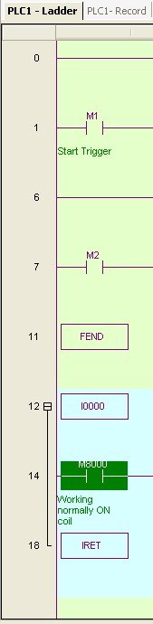
Important: To ensure that the interrupt routines are not executed without an interrupt being present, the main program must be terminated with FEND before the interrupt routine section begins.
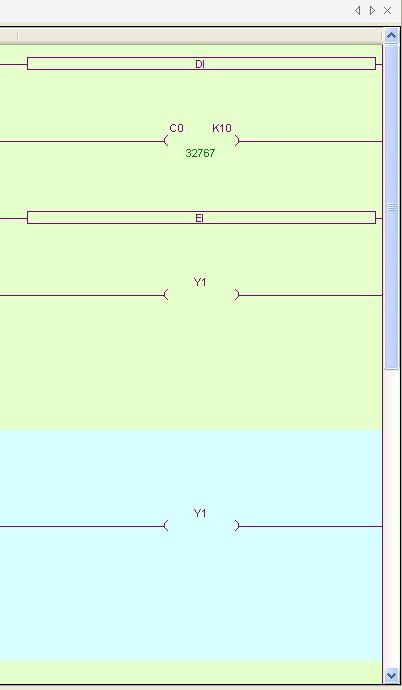
Example: Simple interrupt routine. Line 1 is not interrupted by the input interrupt. FEND prevents the interrupt routine from being executed even without an interrupt.
Exercise
Implement a simple time interrupt that increments a counter by 10 every 10 ms using a FOR NEXT loop.
