


General information
The XC series has a PID command with auto-tuning function that is very versatile and easy to parameterize for such small controllers. The command can be entered directly in the editor or parameterized and added via the command menu above. If added manually, the syntax is as follows:
PID Setpoint SV (Word) Measured value PV (Word) Parameter (Word, 43 Words long!) Output (Word / Bit)
Setpoint can be a constant (K/H) or a register (D), measured value an analog input (ID) or a register (D) and output can be a register (D), an analog output (QD) or a bit (e.g. Y, M etc). For parameterization, a register D must be specified for the start range of the 43-word parameter range. Be careful that other instructions do not inadvertently write here. The location of the individual parameters is described in the manual in chapter 8, the parameters are briefly explained below.
Tip: It is strongly recommended to place the parameters of a PID block in the battery-buffered area. Alternatively, the corresponding registers can also be initialized from flash registers (FD) during the first scan. The command itself is therefore quickly added. The parameterization can be carried out either via the corresponding registers or via the parameterization mask of the block in the function menu above. Simply move the cursor to the relevant block and select the PID button. A menu appears:
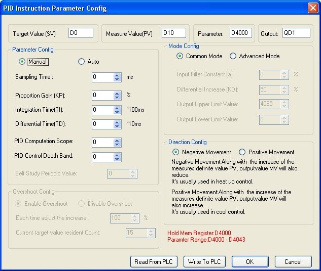
At the bottom right you will once again find the note that the parameters use 43 registers. Important: The current parameters can be read or written via Read From PLC and Write To PLC.
The parameters briefly explained
Auto / Manual
Activates or deactivates auto-tuning of the parameters KP, TI and TD.
Sampling Period
The cycle time of the controller in ms (a 32-bit unsigned integer is transferred). The manual recommends a 100 to 1000-fold multiple of the cycle time.
KP, TI and TD
The control coefficients. If Auto-Tune is activated, they cannot be changed.
PID Computation Scope
The range (absolute) in which control takes place. With a setpoint of 100 and a control range of 10, the controller is only active in the range 90 to 110. Outside of 90 or 110, the output is completely open or closed.
PID Control Death Band
A dead band (absolute) within which the control output is not changed. If the dead band is 3, the controller only reacts by changing the output if the change is greater than 3.
Self-Study Periodic Value
???
Enable / Disable Overshoot
This parameter is only available in auto-tune mode. When disabled, it prevents the measured value from overshooting the setpoint during tuning. This is particularly relevant for controls where an excessively high value is unsafe, e.g. pressure.
Each Time Adjust Increase
A very cryptic parameter at first glance. Is only active if overshooting is to be prevented. Specified in %. To prevent overshooting, the controller approaches the actual setpoint via temporarily lower setpoints. At 80%, the controller therefore sets a temporary setpoint at 80% of the remaining deviation. With a measured value of 0 and a setpoint of 100, it sets a temporary setpoint at 80. The lower this value, the slower the control, but the less the measured value overshoots.
Current Value Resident Count
Similarly cryptic name. Determines how long temporarily lower setpoints should remain active. The higher this value, the slower the controller reacts but the less it overshoots.
Advanced mode
Further settings can be made in advanced mode: Input filter (in %), KD (in %), maximum value of the output (preset is 4095, corresponds to the 12-bit resolution of the analog outputs), minimum value of the output (preset is 0)
Direction Config
This setting is not available if auto-tuning is active. Negative Movement means: if the measured value increases, the output value decreases (heating). Positive Movement means: if the measured value increases, the output value (cooling) also increases.
This should make it easy to implement simple controls.
