


Interfaces
The CPUs of the XC series have up to 4 communication interfaces. The XC3-14 models have only one RS232 COM1 port. This is used to download the program, but can also be connected to an HMI or peripherals. The XC3-14 cannot be expanded. The larger CPUs have 2 serial ports and can be extended by one serial port. The XC5 also has a CAN bus connection. Here is a list of the interfaces:
- COM1 - RS232 programming port, available on all devices, free parameterization, supports Modbus RTU master / slave and free serial communication
- COM2 - RS485 interface, not available on XC3-14, free parameterization, supports Modbus RTU Master / Slave and free serial communication
- COM3 - additional RS232/485 interface, optional as CPU expansion card, free parameterization, supports Modbus RTU master / slave and free serial communication
- COM4 - CAN interface, only available in XC5
The interfaces can be parameterized via the XCPPro software or via flash registers. In XCPPro you will find the settings in the project tree. You can make settings there and transfer them to the CPU via Write PLC. Information on where these settings are located in the flash registers can be found in chapter 7 of the programming manual.
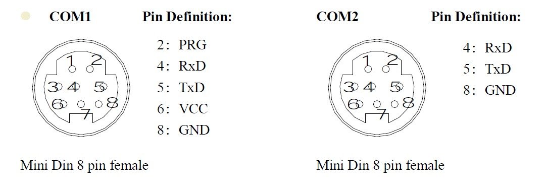
The PIN assignment for COM1 and COM2. You can find a suitable cable in the store.
Useful tip: Restoring the standard parameters for COM1
It is possible that COM1 is set in such a way that you cannot access the CPU with the PC. In this case, a little trick helps to restore the standard parameters for COM1. To do this, simply connect the PC to the CPU via a serial cable. Then select the "Stop PLC When Reboot" function in the "Online" menu in XCPPro. The PC now sends a special reset code for COM1. In order for the CPU to accept this, it must be rebooted (briefly interrupt the power supply) while the PC is sending the stop command to the CPU. The CPU is then stopped and COM1 has standard parameters again and you can access the CPU via the PC. This has already saved me once.
Communication with the periphery
In principle, 3 protocols are available for communication with peripheral devices: Modbus RTU, free serial communication and CAN. Please note: only the XC5 models have a CAN bus interface.
Modbus master communication
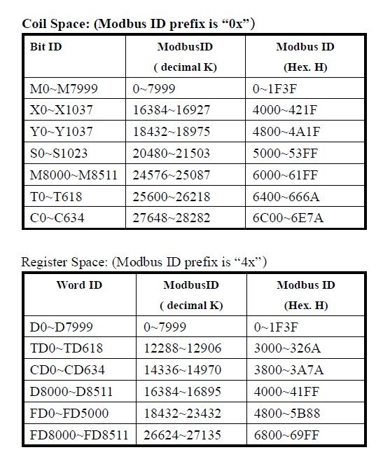
All 3 serial COM ports support Modbus master communication. Station number and serial parameters can be freely configured on all ports. The implementation of Modbus communication is very simple, special Modbus commands are available. As a reminder, a very simplified description of the protocol. In Modbus, certain memory areas of a device are mapped to Modbus addresses. Here are the most important ones:
- Coils - read / write bits
- Discrete Inputs - read bits only
- Holding Registers - read / write words
- Input registers - read only words
There are various commands for accessing these address ranges, here are the most important ones:
- 01 Read Coil
- 02 Read Input Bit
- 03 Read Holding Register
- 04 Read Input Registers
- 05 Write Single Coil
- 06 Write Single Holding Register
- 15 Write Multiple Coils
- 16 Write Multiple Holding Registers
The Modbus commands have been implemented in the XC-PLC in exactly the same way and are very easy to use.
- COLR - 01 Coil Read; the syntax is COLR Destination station ID (Word) Destination start address (Word) Length (Word) Storage bit (Bit) Port (Word)
Example: COLR K20 K10 K3 M0 K1 - Reads coils 10 to 12 from station 20 via port 1 and stores them in M0 to M2.
(Data registers can of course also be transferred instead of constants). - INPR - 02 Input Read; the syntax: INPR Target station ID (Word) Target start address (Word) Length (Word) Storage bit (Bit) Port (Word)
Example: INPR K12 K0 K3 M0 K2 - Reads the input bits 0 to 2 from station 12 via port 2 and stores them in M0 to M2. - REGR - 03 Register Read; the syntax: REGR Destination station ID (Word) Destination start address (Word) Length (Word) Storage register (Word) Port (Word)
Example: REGR K3 K0 K3 D0 K3 - Reads the holding registers 0 to 2 from station 3 via port 3 and stores them in D0 to D2. - INRR - 04 Input Register Read; the syntax: INRR Destination station ID (Word) Destination start address (Word) Length (Word) Storage register (Word) Port (Word)
Example: INRR K3 K0 K3 D0 K3 - Reads the input registers 0 to 2 from station 3 via port 3 and stores them in D0 to D2. - COLW - 05 Coil Write, writes a single bit; the syntax is COLW Destination station ID (Word) Destination address (Word) Local source bit (Bit) Port (Word)
Example: COLW K20 K10 X0 K1 - Writes the content of X1 to coil 10 via port 1 on station 20. - REGW - 06 Register Write, writes a single register; the syntax is REGW Destination station ID (Word) Destination address (Word) Local source register (Word) Port (Word)
Example: REGW K20 K3 CD10 K1 - Writes the contents of counter 10 to holding register 3 via port 1 on station 20. - MCLW - 15 Multiple Coil Write, writes several coils; the syntax is MCLW Destination station ID (Word) Destination address (Word) Length (Word) Local source bit (Bit) Port (Word)
Example: MCLW K2 K10 K5 Y0 K1 - Writes coils 10 to 14 with the content of outputs Y0 to Y4 via port 1 on station 2. - MRGW - 16 Multiple Register Write, writes several holding registers; the syntax is MRGW Destination station ID (Word) Destination address (Word) Length (Word) Local source register (Word) Port (Word)
Example: MRGW K5 K4 K7 FD8210 K1 - Writes the contents of flash registers 8210 to 8216 to holding registers 4 to 10 via port 1 on station 5.
Incidentally, these flash registers contain the interface parameters for COM1 ;-). For more details, see chapter 7 of the manual.
Communication with Modbus peripherals is therefore very simple.
Tip: Sequence blocks are ideal for implementing cyclical Modbus communication. With a positive edge on our M8013 shaker, I can execute several Modbus communication commands every second via a sequence block and, for example, query the entire periphery. Attention: The parameters of the Modbus commands must also be transferred as constants (e.g. K10 or H20) or data registers in the configuration mask in the sequence block, otherwise there will be an error message.
Free serial communication
Free serial communication is suitable for serial devices that do not support Modbus, such as barcode readers. All three possible serial COM ports support free communication. To activate free communication, the station address of the port must be set to 255. A start and end byte can also be added in the configuration for free communication. These are then automatically added with every send or receive or removed before being stored in the register. 8 and 16 bit communication is possible, in 8 bit communication only the low bytes are taken into account, the high bytes are ignored. Further information on the parameterization of serial communication can be found in chapter 7 of the programming manual.
The two commands for free communication are easy to implement:
- SEND Word (start address source register) Word (length) Word (port) - Example SEND D0 K1 K2 sends the contents of D0 via COM2.
M8132 is set during the sending process on COM2. - RCV Word (start address destination register) Word (length) Word (port) - Example RCV D0 K1 K2 writes the first word from COM2 to register D0.
M8134 is set during the receive process on COM2.
The fastest access to the communication flags for the three ports can be found in the Comment Editor.
Tip: Sequence blocks and Config blocks with Free Comm Config can be used to implement standardized free serial communication. The configuration of the free communication is completely the same in both blocks, in the Sequence Block you can also insert other sequential actions. You can use these Free Comm Config blocks to implement your own simple serial protocols.
Peer2Peer communication
Modbus RTU is particularly suitable for Peer2Peer communication with other THINGET PLCs or PLCs from other manufacturers. As the XC series can handle both Modbus Master and Modbus Slave, it can communicate with devices from almost all manufacturers. The mapping address for the XC series as a Modbus slave can be found in the next section. The XC5 PLC can also exchange data with other XC5s at high speed via the CAN interface.
CAN
In addition to COM1, COM2 and the optional serial COM3 interface, the XC5 models have a CAN interface. Two contacts, one CAN+ and one CAN-, are provided on the CPU for this purpose. The XC5 supports two CAN communication types for communication with other XC5 controllers and free CAN communication. CANopen is not yet supported.
The CAN station number can be set via the project tree on the left as well as via a flash register. CAN communication as a master-slave protocol with other XC5 controllers is realized in the XC5 via the following commands:
- CCOLR - CAN Coil Read; the syntax is CCOLR Destination participant ID (Word) Source address (Word) Length (Word) Storage bit (Bit)
Example: CCOLR K20 K10 K3 M0 - Reads coils 10 to 12 from subscriber 20 and stores them in M0 to M2.
(Data registers can of course also be transferred instead of constants).
- CCOLW - CAN Coil Write; the syntax is CCOLW Destination participant ID (Word) Destination address (Word) Length (Word) Source start bit (Bit)
Example: CCOLR K10 K5 K3 M0 - Writes the contents of M0 to M2 to coils 5 to 7 on node 10.
- CREGR - CAN Register Read; the syntax is CREGR Destination participant ID (Word) Source address (Word) Length (Word) Storage word (Bit)
Example: CREGR K20 K10 K3 D2 - Reads registers 10 to 12 from subscriber 20 and stores them in D2 to D4.
- CREGW - CAN Register Write; the syntax is CREGW Destination node ID (Word) Destination address (Word) Length (Word) Source start register (Bit)
Example: CREGR K10 K5 K3 D7 - Writes the contents of D7 to D9 to registers 5 to 7 on node 10.
In addition, a cyclical exchange with other XC5 nodes can be configured via the CAN configuration in the project tree or via flash registers. More details can be found in chapter 7 of the programming manual.
Free CAN communication isrealized in the XC5 via the commands CSEND (Can Send) and CRCV (Can Receive). Details can also be found in Chapter 7 of the programming manual.
Communication with the HMI
The easiest way to use an HMI in combination with the XC series is to use the THINGET TouchWin TH HMI from the same manufacturer. HMIs are really plug & play, I was surprised at how easy it works. Simply connect the HMI (cables are available in the store), open a new project in TouchWin, select the XC on the PLC port and start visualizing. Addressing is simply done via the memory areas, which you should know quite well by now.
The Modbus slave protocol is ideal for communication with other HMIs. All 3 possible serial COM ports support Modbus slave communication, parallel to Modbus master communication. Here is the mapping table:
Even if not all bits are actually writable, they are in the Modbus range of writable coils (address starts with 0). The registers are located in the holding register area (addressing starts with 4, then the 5 described digits). Further details on communication can be found in chapter 7 of the programming manual.
