


How do I actually convert a 4 - 20 mA value?
May 21, 2016
Steffen
How-to-Guides FAQ
How-to-Guides FAQ
A technical question that often reaches us is: How do I actually convert a 4 - 20 mA signal in the PLC? The short answer is: not at all. You can find the long answer here:
The 4 - 20 mA is actually not interesting.
The 4 to 20 mA signal (or the alternative 0 - 10 V signal) is often used in automation for the transmission of analogue values, for example, for the transmission of measured values from a pressure sensor. The measured value is converted by the sensor into an electrical signal whose current strength is set between 4 and 20 mA depending on the measured value. If the measured value is at the lower end of its scale, for example 0 bar, the signal is set to 4 mA. If the measured value is at the upper end, perhaps 10 bar, then the signal from the sensor is set to 20 mA. Values lower than 4 mA and higher than 20 mA are invalid. Measured values in between generate a signal somewhere between 4 and 20 mA accordingly.
The receiving device, for example an analogue input of a PLC, picks up this signal and converts it internally. And it does so in its own value range, which has nothing at all to do directly with the values 4 to 20. This means that the 4 to 20 mA are only the carrier signal. The exact value in mA is completely uninteresting for the application. Only in case of deviations and problems is it worthwhile to measure the current of the sensor directly. For the application, you can mentally hide this.
The resolution of the analogue input module is crucial
What does the value range of the input value in the PLC depend on then? So it is not a value between 4 - 20 mA and also not yet the measured value of the sensor, 0 - 10 bar in our example. The PLC does not yet know the measuring range of the sensor.
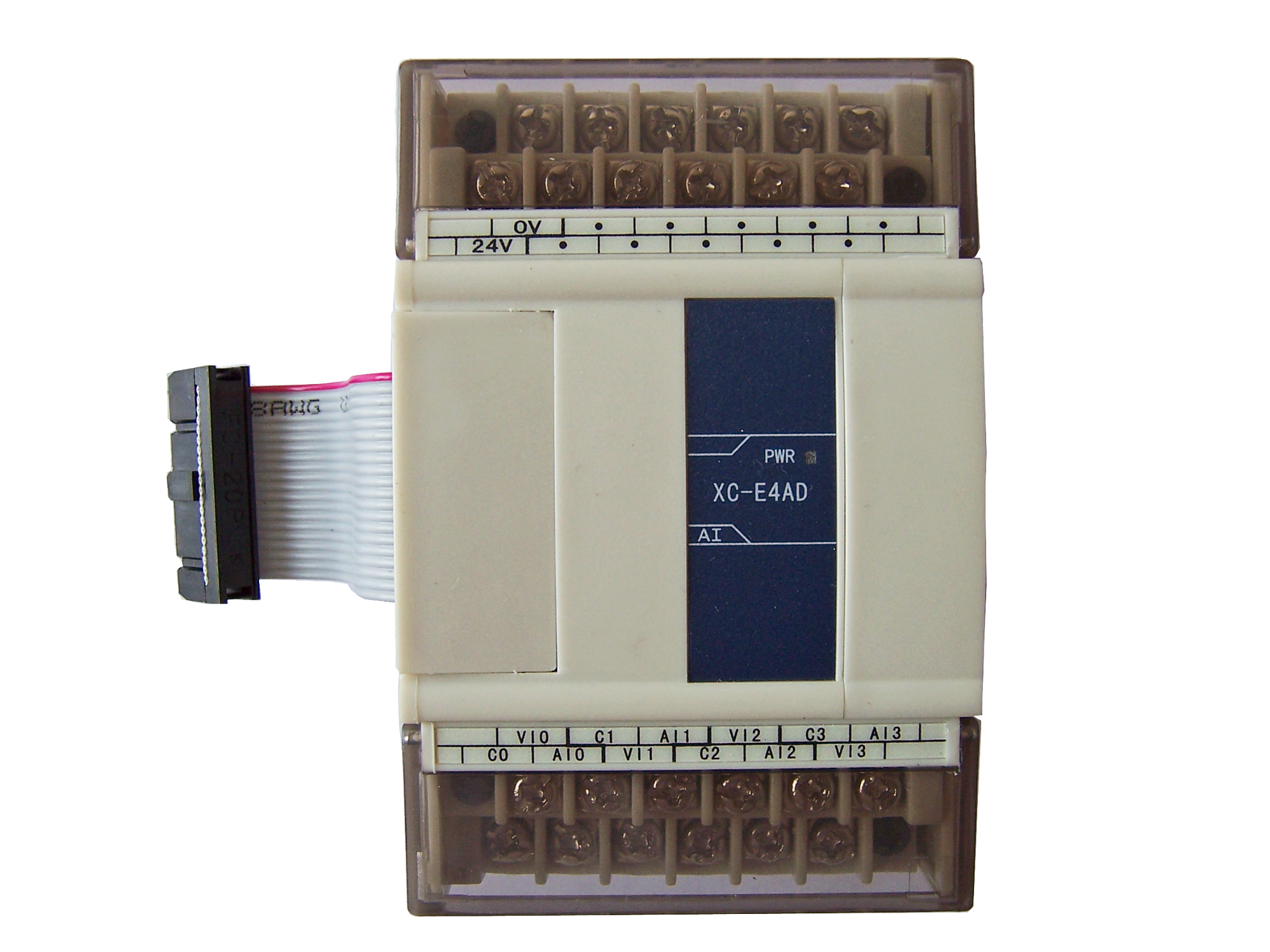
The correct answer to the question about the value range is: It depends. It depends on the digital resolution of the input, for example in the PLC. The PLC converts the electrical signal into its own digital value. Depending on the resolution in bits available for this conversion, the value range changes. The analogue input modules of the Thinget PLC, for example, have 14 bits of resolution. This means that the value can have 2^14 different states, i.e. 16.384. The value range of the signal is therefore somewhere between 0 and 16.383 (note that the value range starts at 0 and ends at 2^14 - 1.) 0 then corresponds to 4 mA or 0 bar and 16.383 to the maximum value, i.e. 20 mA or 10 bar in our example. Again, the 4 - 20 mA as a number do not matter. 0 corresponds to the lowest measured value and 16.383 to the highest measured value. If the resolution of the processing module is only 12 bits, then the value range is correspondingly 0 - 4.095 i.e. 0 to 2^12 -1.
The conversion formula
How do I then convert this value in the PLC, i.e. 0 to 16.383 back into the actual measured value? Simple. Each change of 1 in the value corresponds to the 16,384th part of the value range. In our example, the value range is between 0 and 10 bar, so the span is exactly 10 bar. A change of the received value in the PLC by 1 therefore means a change of the measured value by 1 / 16.384 of the value range, i.e. 10 bar / 16.384 and thus 0.0006103515625 bar. This is therefore our unit for the change of the digital value in the PLC. If the value in the PLC changes by 100, this corresponds to a change in the measured value of 100 times the change in the value range of 10 bar / 16.384 i.e. 0.0006103515625 bar * 100, i.e. 0.06103... about 61 mbar.
So the formula for converting the digital value in the PLC back to the measured value is in our example:
100 * (10 bar / 16.384) = 0.061035... bar = 61.035... mbar
Value in the PLC * (span of the measured value / resolution of the input module in number of possible values) = Measured value in the unit of the measured value.
What if the range of values does not start at 0?
Then it gets a bit more complicated, but is actually just as simple. Let's assume that our measuring range is now between 1 and 10 bar. Then span of the measuring range is exactly 9 bar (10 bar - 1 bar). So our resolution of 16,384 different values now covers a range of 9 bar. A change of the value in the PLC by 1 corresponds to a change of the measured value by 9 bar / 16,384, i.e. 0.00054931640625. At the same time, the value 0 in the PLC no longer corresponds to 0 bar but to 1 bar. You must therefore add the calculated value to 1 bar, the initial value at 0 in the PLC.
This means for our example value 100 in the PLC:
1 bar + 100 * ( 9 bar / 16.384) = 1 bar + 100 * 0.000549... bar = 1.0549... bar
Measured value at 0 + value in the PLC * (span of the measured value / resolution of the input module) = Measured value in the unit of the measured value.
How scaling works in the PLC using the Thinget XC and Kinco K2 as an example.
How the calculation works in the PLC is shown using the Thinget XC and Kinco K2 as an example.
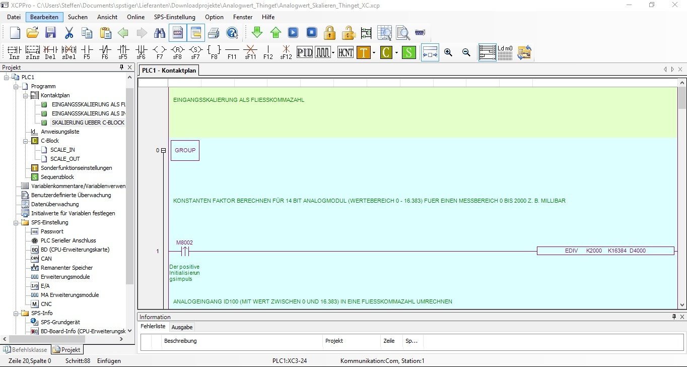
In the XC PLC from Thinget, the analogue inputs of the analogue expansion module are in the address range ID. Address ID100 is then analogue input CH0 if the analogue module is plugged into extension slot 1. The 4 - 20 mA value now arrives at address ID100 as a 14-bit value, i.e. with a value between 0 and 16.383. Let's assume that the transmitted value is 1.345. We now want to convert this into a value in millibars. The value range of the sensor is 0 to 2,000 millibars.
There are now two ways to convert this value in the Thinget XC-SPS. Either via integer operations or floating point operations. We start with the floating point variant.
First we calculate the constant factor measuring range sensor / value range of the input, i.e. 2000 / 16.384. Since the result is a floating point number, we use the EDIV function (floating point division). We store the result in the memory area D4000. Since the result is a double word of 32 bits, this occupies D4000 and D4001.
EDIV K2000 K16384 D4000
K stands for a constant number in the Thinget software. Now we just have to multiply the value ID100 by this number. For this to work, however, we must first convert ID100 into a floating point number. The command for this is FLT, with this command we transfer the value of ID100 as a floating point number into register D1000.
FLT ID100 D1000
Now we just have to multiply our factor D4000 by D1000, we store the result directly back into D1000 to use the memory efficiently:
EMUL D1000 D4000 D1000
So D1000 now contains the correct value of the sensor in millibar as a floating point number. The calculation with an initial value other than 0 is done as described in the general calculation.
We have created an example programme for the Thinget PLC for the conversion of analogue values. It contains the conversion in ladder diagram as well as two C blocks for the conversion.
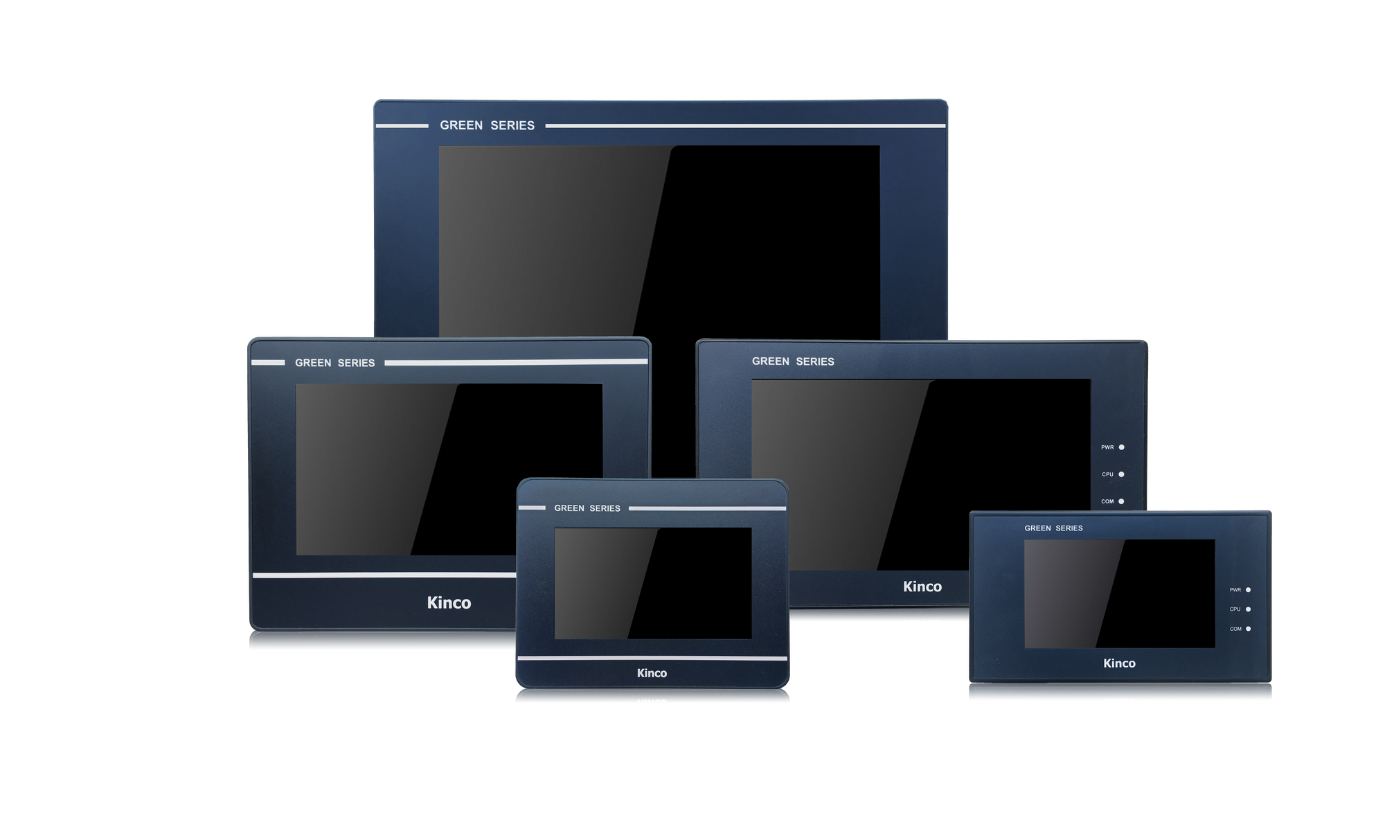
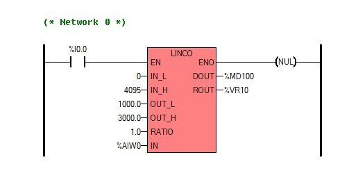
In the Kinco software (Kinco Builder) for the K2 and K5 PLCs, a block for the conversion is directly available. This is called LINCO for linear scaling. As input values, the module has the variables IN_L for the lowest value of the input range, i.e. 0 in the case of an analogue input IN_H for the highest value, i.e. e.g. 4095 for a 12-bit input like the K2 has. As OUT_L and OUT_H you set the minimum and maximum values of the output range, for example 1,000 mbar to 3,000 mbar. Ratio is a scaling factor, for example 2, to double the output value. Finally, IN is the input value of the sensor, for example %AIW0.
On the output side of the component, the scaled output value is also available as a double word (DOUT) and floating point number (ROUT).
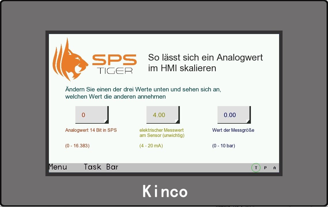
You can also scale the analogue value in the HMI first.
If you do not need the value in the PLC programme any further in the programme sequence, but want to display it in the HMI first, you can also scale it in the HMI. For this purpose, a scaling function is available in the "Numeric Data" tab in Number Display and Number Input. There you enter the value range in the PLC for Min and Max, for example 0 to 4.095 for an input with 12-bit resolution. Under "Proportion Conversion" in the bottom right-hand corner, enter the value range that is to be displayed, for example 0 - 10 bar. The values Integer and Decimal then refer to the displayed digits before and after the decimal point for the scaled value.
Your spstiger
Related products

